Page 4572 of 6000
6A–76
ENGINE MECHANICAL
012RS001
7. Install oil pump assembly (5), refer to “Oil pump” in
this manual.
8. Install oil strainer and O-ring (4).
9. Install oil pipe and O-ring (3) and tighten the bolts.
Torque: 25 Nꞏm (2.5 Kgꞏm/18 lb ft)
10. Install crankcase with oil pan (2).
1. Completely remove all residual sealant, lubricant
and moisture from the sealing surfaces. The
surfaces must be perfectly dry.
2. Apply a correct width bead of sealant (TB—
1207C or its equivalent) to the contact surfaces of
the oil pan. There must be no gaps in the bead.
3. The crankcase assembly must be installed within
5 minutes after sealant application to prevent
premature hardening of the sealant.
4. Tighten the bolts and nuts to the specified torque.
Torque : 10 Nꞏm (1.0 Kgꞏm/89 lb in)
013RW010
Legend
(1) Portion Between Bolt Holes
(2) Bolt Hole Portion
11. Install cylinder head assembly, refer to “Cylinder
head” in this manual.
Page 4578 of 6000
6A–82
ENGINE MECHANICAL
4. Reinstall the rod caps (12) to their original
positions.
Tighten the rod cap nuts.
Torque: 54 Nꞏm (5.5 Kgꞏm/40 lb ft)
NOTE: Do not allow the crankshaft to rotate.
5. Remove the rod caps.
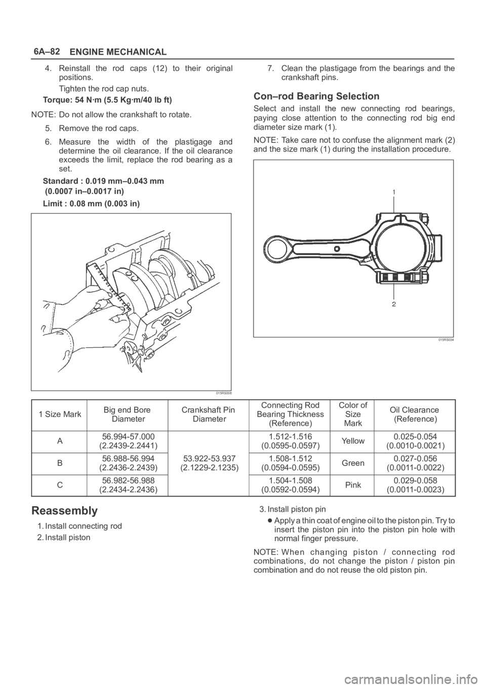
6. Measure the width of the plastigage and
determine the oil clearance. If the oil clearance
exceeds the limit, replace the rod bearing as a
set.
Standard : 0.019 mm–0.043 mm
(0.0007 in–0.0017 in)
Limit : 0.08 mm (0.003 in)
015RS008
7. Clean the plastigage from the bearings and the
crankshaft pins.
Con–rod Bearing Selection
Select and install the new connecting rod bearings,
paying close attention to the connecting rod big end
diameter size mark (1).
NOTE: Take care not to confuse the alignment mark (2)
and the size mark (1) during the installation procedure.
015RS034
1 Size MarkBig end Bore
DiameterCrankshaft Pin
DiameterConnecting Rod
Bearing Thickness
(Reference)Color of
Size
MarkOil Clearance
(Reference)
A56.994-57.000
(2.2439-2.2441)1.512-1.516
(0.0595-0.0597)Ye l l o w0.025-0.054
(0.0010-0.0021)
B56.988-56.994
(2.2436-2.2439)53.922-53.937
(2.1229-2.1235)1.508-1.512
(0.0594-0.0595)Green0.027-0.056
(0.0011-0.0022)
C56.982-56.988
(2.2434-2.2436)1.504-1.508
(0.0592-0.0594)Pink0.029-0.058
(0.0011-0.0023)
Reassembly
1. Install connecting rod
2. Install piston3. Install piston pinApply a thin coat of engine oil to the piston pin. Try to
insert the piston pin into the piston pin hole with
normal finger pressure.
NOTE: When changing piston / connecting rod
combinations, do not change the piston / piston pin
combination and do not reuse the old piston pin.
Page 4580 of 6000
6A–84
ENGINE MECHANICAL
Tighten the connecting rod cap nuts
Torque : 54 Nꞏm (5.5 Kgꞏm/40 lb ft)
NOTE: Do not apply engine oil to the bearing back faces.
6. Oil gallery, refer to “Crankshaft and main bearing” in
this manual.
7. Oil strainer and O-ring.
8. Oil pipe and O-ring.
9. Install crankcase with oil pan, refer to “Oil pan and
Crankcase” in this manual.
10. Install cylinder head gasket.
11. Install Cylinder head assembly.
Refer to “Cylinder head” in this manual.
Page 4583 of 6000
6A–87
ENGINE MECHANICAL
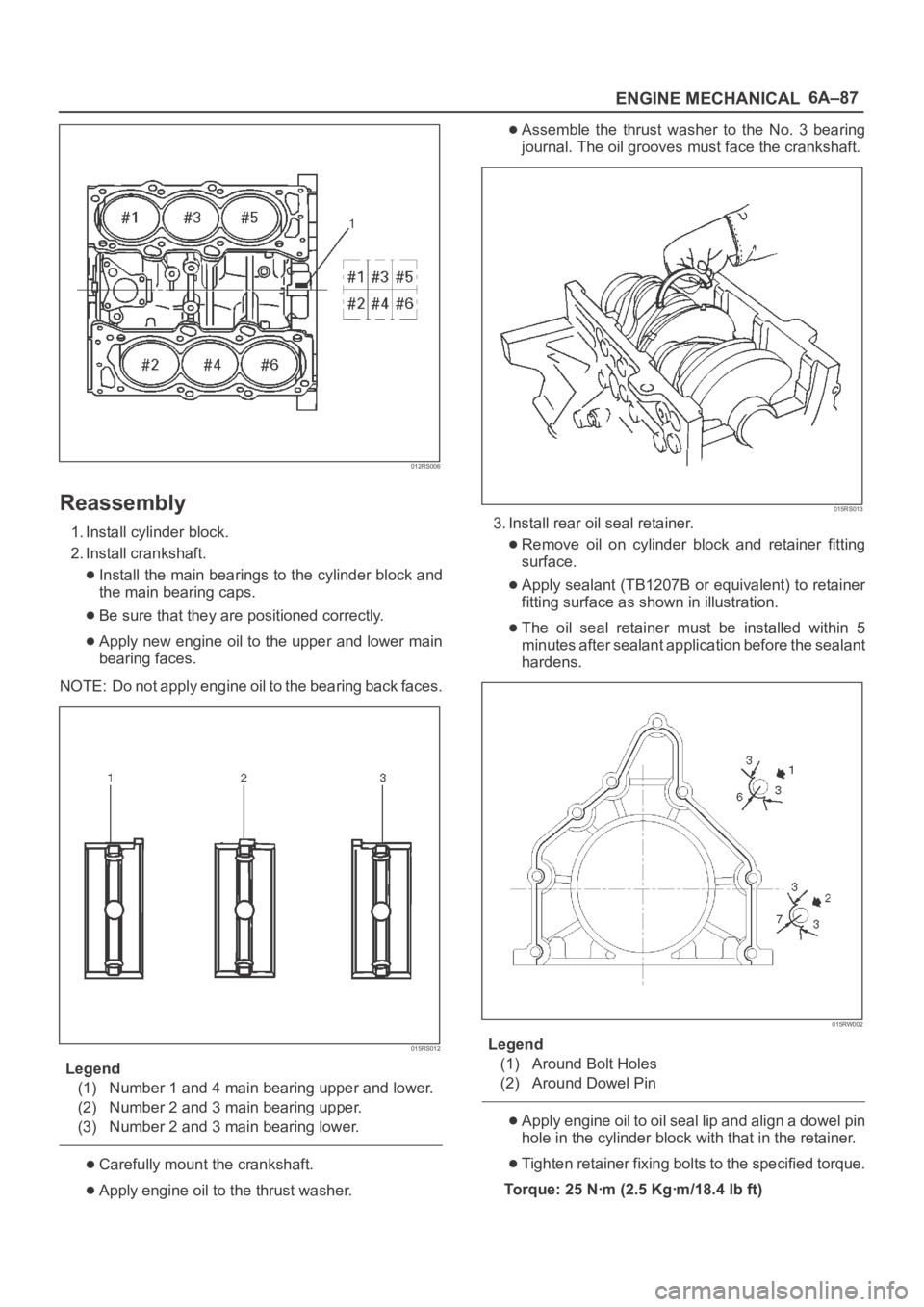
012RS006
Reassembly
1. Install cylinder block.
2. Install crankshaft.
Install the main bearings to the cylinder block and
the main bearing caps.
Be sure that they are positioned correctly.
Apply new engine oil to the upper and lower main
bearing faces.
NOTE: Do not apply engine oil to the bearing back faces.
015RS012
Legend
(1) Number 1 and 4 main bearing upper and lower.
(2) Number 2 and 3 main bearing upper.
(3) Number 2 and 3 main bearing lower.
Carefully mount the crankshaft.
Apply engine oil to the thrust washer.
Assemble the thrust washer to the No. 3 bearing
journal. The oil grooves must face the crankshaft.
015RS013
3. Install rear oil seal retainer.
Remove oil on cylinder block and retainer fitting
surface.
Apply sealant (TB1207B or equivalent) to retainer
fitting surface as shown in illustration.
The oil seal retainer must be installed within 5
minutes after sealant application before the sealant
hardens.
015RW002
Legend
(1) Around Bolt Holes
(2) Around Dowel Pin
Apply engine oil to oil seal lip and align a dowel pin
hole in the cylinder block with that in the retainer.
Tighten retainer fixing bolts to the specified torque.
Torque: 25 Nꞏm (2.5 Kgꞏm/18.4 lb ft)
Page 4584 of 6000
6A–88
ENGINE MECHANICAL
015RW001
4. Install flywheel
1. Thoroughly clean and remove the oil from the
threads of crankshaft.
2. Remove the oil from the crankshaft and flywheel
mounting faces.
3. Mount the flywheel on the crankshaft and then
install the washer.
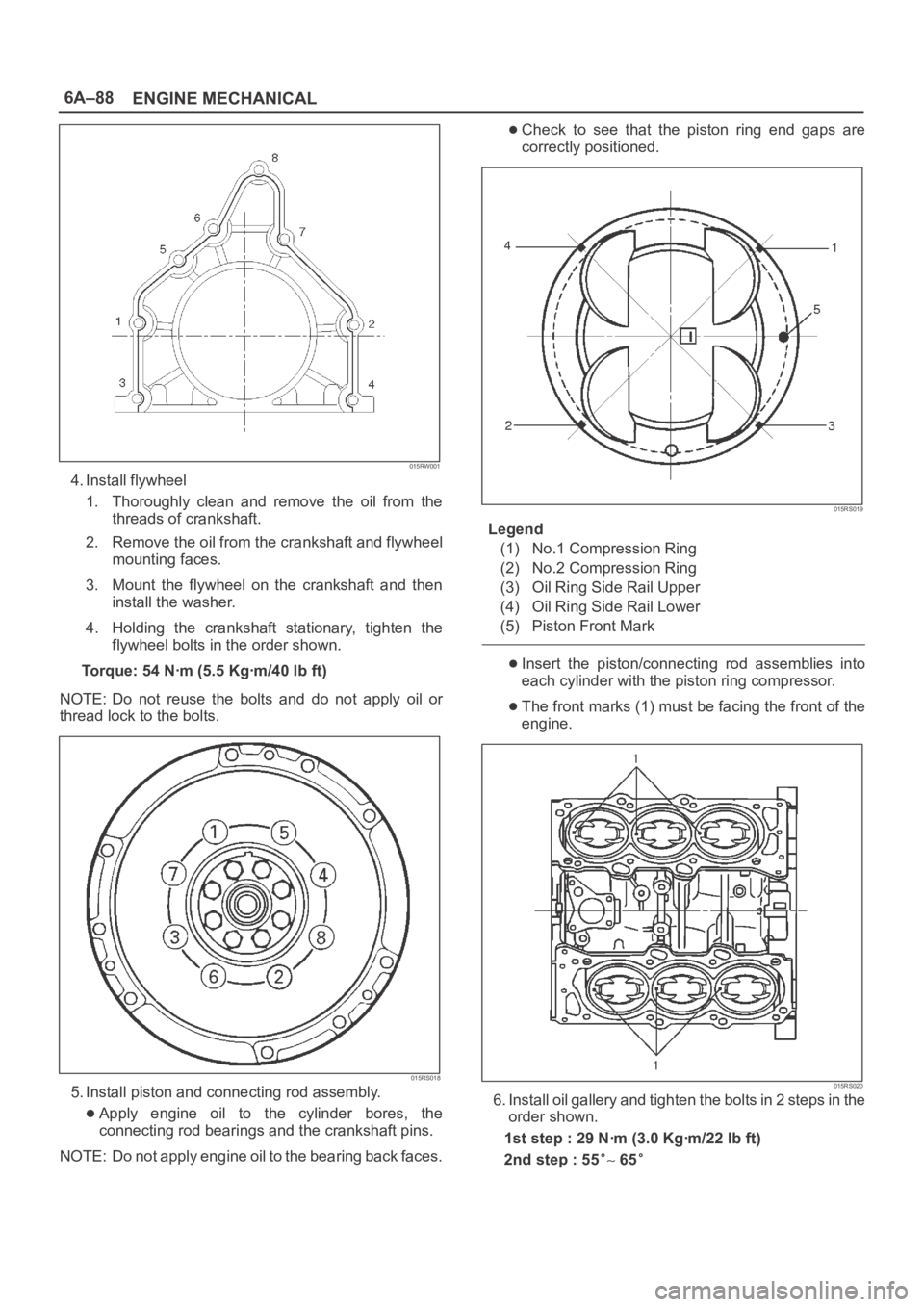
4. Holding the crankshaft stationary, tighten the
flywheel bolts in the order shown.
Torque: 54 Nꞏm (5.5 Kgꞏm/40 lb ft)
NOTE: Do not reuse the bolts and do not apply oil or
thread lock to the bolts.
015RS018
5. Install piston and connecting rod assembly.
Apply engine oil to the cylinder bores, the
connecting rod bearings and the crankshaft pins.
NOTE: Do not apply engine oil to the bearing back faces.
Check to see that the piston ring end gaps are
correctly positioned.
015RS019
Legend
(1) No.1 Compression Ring
(2) No.2 Compression Ring
(3) Oil Ring Side Rail Upper
(4) Oil Ring Side Rail Lower
(5) Piston Front Mark
Insert the piston/connecting rod assemblies into
each cylinder with the piston ring compressor.
The front marks (1) must be facing the front of the
engine.
015RS020
6. Install oil gallery and tighten the bolts in 2 steps in the
order shown.
1st step : 29 Nꞏm (3.0 Kgꞏm/22 lb ft)
2nd step : 55
65
Page 4585 of 6000
6A–89
ENGINE MECHANICAL
012RS007
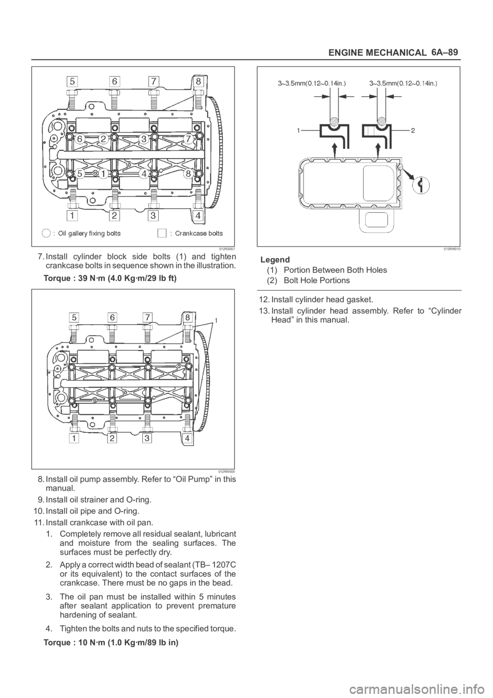
7. Install cylinder block side bolts (1) and tighten
crankcase bolts in sequence shown in the illustration.
Torque : 39 Nꞏm (4.0 Kgꞏm/29 lb ft)
012RW005
8. Install oil pump assembly. Refer to “Oil Pump” in this
manual.
9. Install oil strainer and O-ring.
10. Install oil pipe and O-ring.
11. Install crankcase with oil pan.
1. Completely remove all residual sealant, lubricant
and moisture from the sealing surfaces. The
surfaces must be perfectly dry.
2. Apply a correct width bead of sealant (TB– 1207C
or its equivalent) to the contact surfaces of the
crankcase. There must be no gaps in the bead.
3. The oil pan must be installed within 5 minutes
after sealant application to prevent premature
hardening of sealant.
4. Tighten the bolts and nuts to the specified torque.
Torque : 10 Nꞏm (1.0 Kgꞏm/89 lb in)
013RW010
Legend
(1) Portion Between Both Holes
(2) Bolt Hole Portions
12. Install cylinder head gasket.
13. Install cylinder head assembly. Refer to “Cylinder
Head” in this manual.
Page 4587 of 6000
6A–91
ENGINE MECHANICAL
Torque Specifications
Ignition coil, Spark plug, Crankshaft angle sensor and Under cover
Nꞏm (Kgꞏm/Ib ft)
E06RW038
Page 4594 of 6000
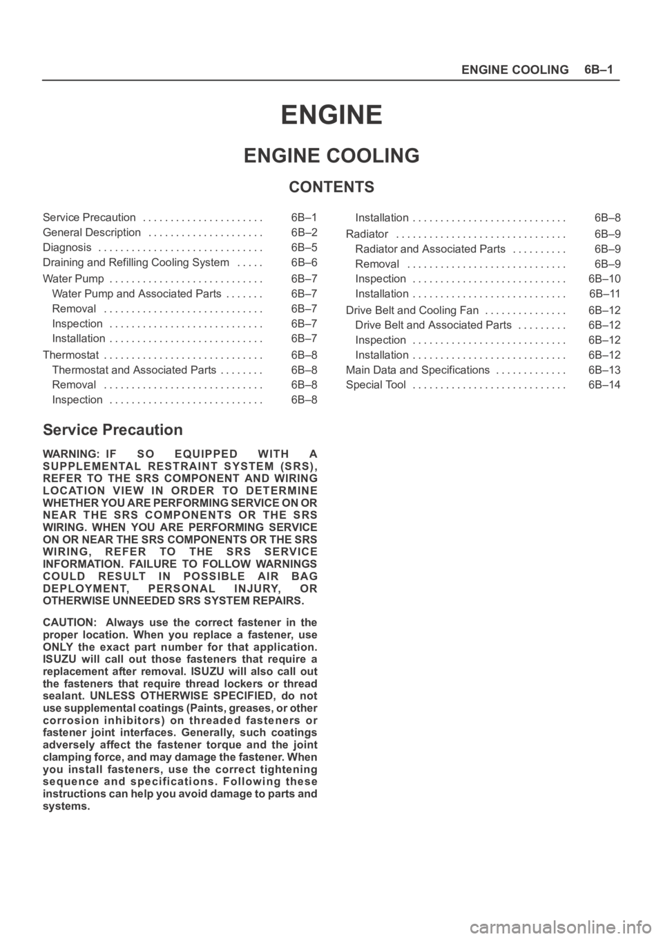
ENGINE COOLING6B–1
ENGINE
ENGINE COOLING
CONTENTS
Service Precaution 6B–1. . . . . . . . . . . . . . . . . . . . . .
General Description 6B–2. . . . . . . . . . . . . . . . . . . . .
Diagnosis 6B–5. . . . . . . . . . . . . . . . . . . . . . . . . . . . . .
Draining and Refilling Cooling System 6B–6. . . . .
Water Pump 6B–7. . . . . . . . . . . . . . . . . . . . . . . . . . . .
Water Pump and Associated Parts 6B–7. . . . . . .
Removal 6B–7. . . . . . . . . . . . . . . . . . . . . . . . . . . . .
Inspection 6B–7. . . . . . . . . . . . . . . . . . . . . . . . . . . .
Installation 6B–7. . . . . . . . . . . . . . . . . . . . . . . . . . . .
Thermostat 6B–8. . . . . . . . . . . . . . . . . . . . . . . . . . . . .
Thermostat and Associated Parts 6B–8. . . . . . . .
Removal 6B–8. . . . . . . . . . . . . . . . . . . . . . . . . . . . .
Inspection 6B–8. . . . . . . . . . . . . . . . . . . . . . . . . . . . Installation 6B–8. . . . . . . . . . . . . . . . . . . . . . . . . . . .
Radiator 6B–9. . . . . . . . . . . . . . . . . . . . . . . . . . . . . . .
Radiator and Associated Parts 6B–9. . . . . . . . . .
Removal 6B–9. . . . . . . . . . . . . . . . . . . . . . . . . . . . .
Inspection 6B–10. . . . . . . . . . . . . . . . . . . . . . . . . . . .
Installation 6B–11. . . . . . . . . . . . . . . . . . . . . . . . . . . .
Drive Belt and Cooling Fan 6B–12. . . . . . . . . . . . . . .
Drive Belt and Associated Parts 6B–12. . . . . . . . .
Inspection 6B–12. . . . . . . . . . . . . . . . . . . . . . . . . . . .
Installation 6B–12. . . . . . . . . . . . . . . . . . . . . . . . . . . .
Main Data and Specifications 6B–13. . . . . . . . . . . . .
Special Tool 6B–14. . . . . . . . . . . . . . . . . . . . . . . . . . . .
Service Precaution
WARNING: IF SO EQUIPPED WITH A
SUPPLEMENTAL RESTRAINT SYSTEM (SRS),
REFER TO THE SRS COMPONENT AND WIRING
LOCATION VIEW IN ORDER TO DETERMINE
WHETHER YOU ARE PERFORMING SERVICE ON OR
NEAR THE SRS COMPONENTS OR THE SRS
WIRING. WHEN YOU ARE PERFORMING SERVICE
ON OR NEAR THE SRS COMPONENTS OR THE SRS
WIRING, REFER TO THE SRS SERVICE
INFORMATION. FAILURE TO FOLLOW WARNINGS
COULD RESULT IN POSSIBLE AIR BAG
DEPLOYMENT, PERSONAL INJURY, OR
OTHERWISE UNNEEDED SRS SYSTEM REPAIRS.
CAUTION: Always use the correct fastener in the
proper location. When you replace a fastener, use
ONLY the exact part number for that application.
ISUZU will call out those fasteners that require a
replacement after removal. ISUZU will also call out
the fasteners that require thread lockers or thread
sealant. UNLESS OTHERWISE SPECIFIED, do not
use supplemental coatings (Paints, greases, or other
corrosion inhibitors) on threaded fasteners or
fastener joint interfaces. Generally, such coatings
adversely affect the fastener torque and the joint
clamping force, and may damage the fastener. When
you install fasteners, use the correct tightening
sequence and specifications. Following these
instructions can help you avoid damage to parts and
systems.