1998 OPEL FRONTERA tow
[x] Cancel search: towPage 3405 of 6000
8J–26EXTERIOR/INTERIOR TRIM
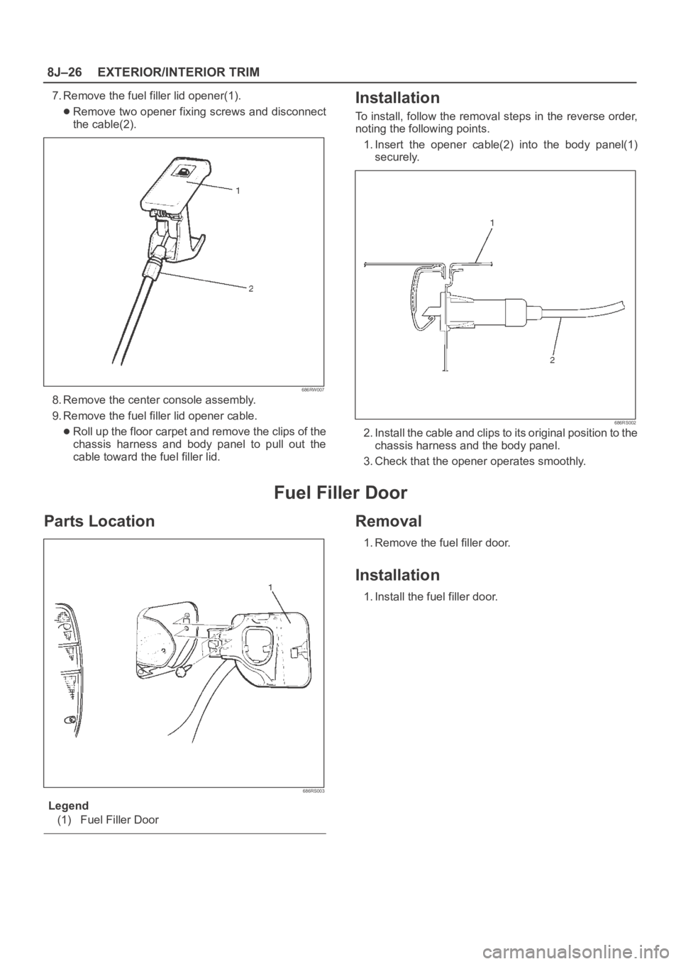
7. Remove the fuel filler lid opener(1).
Remove two opener fixing screws and disconnect
the cable(2).
686RW007
8. Remove the center console assembly.
9. Remove the fuel filler lid opener cable.
Roll up the floor carpet and remove the clips of the
chassis harness and body panel to pull out the
cable toward the fuel filler lid.
Installation
To install, follow the removal steps in the reverse order,
noting the following points.
1. Insert the opener cable(2) into the body panel(1)
securely.
686RS002
2. Install the cable and clips to its original position to the
chassis harness and the body panel.
3. Check that the opener operates smoothly.
Fuel Filler Door
Parts Location
686RS003
Legend
(1) Fuel Filler Door
Removal
1. Remove the fuel filler door.
Installation
1. Install the fuel filler door.
Page 3441 of 6000
SUPPLEMENTAL RESTRAINT SYSTEM 9J–4
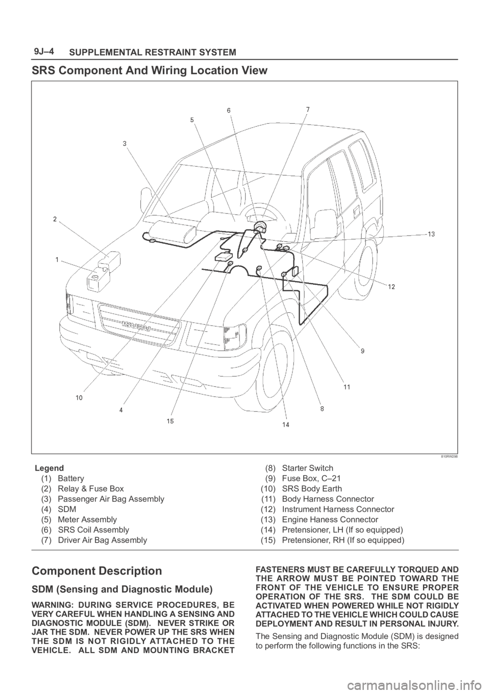
SRS Component And Wiring Location View
810RW298
Legend
(1) Battery
(2) Relay & Fuse Box
(3) Passenger Air Bag Assembly
(4) SDM
(5) Meter Assembly
(6) SRS Coil Assembly
(7) Driver Air Bag Assembly(8) Starter Switch
(9) Fuse Box, C–21
(10) SRS Body Earth
(11) Body Harness Connector
(12) Instrument Harness Connector
(13) Engine Haness Connector
(14) Pretensioner, LH (If so equipped)
(15) Pretensioner, RH (If so equipped)
Component Description
SDM (Sensing and Diagnostic Module)
WARNING: DURING SERVICE PROCEDURES, BE
VERY CAREFUL WHEN HANDLING A SENSING AND
DIAGNOSTIC MODULE (SDM). NEVER STRIKE OR
JAR THE SDM. NEVER POWER UP THE SRS WHEN
THE SDM IS NOT RIGIDLY ATTACHED TO THE
VEHICLE. ALL SDM AND MOUNTING BRACKETFASTENERS MUST BE CAREFULLY TORQUED AND
THE ARROW MUST BE POINTED TOWARD THE
FRONT OF THE VEHICLE TO ENSURE PROPER
OPERATION OF THE SRS. THE SDM COULD BE
ACTIVATED WHEN POWERED WHILE NOT RIGIDLY
ATTACHED TO THE VEHICLE WHICH COULD CAUSE
DEPLOYMENT AND RESULT IN PERSONAL INJURY.
The Sensing and Diagnostic Module (SDM) is designed
to perform the following functions in the SRS:
Page 3448 of 6000
SUPPLEMENTAL RESTRAINT SYSTEM9J–11
Handling / Installation / Diagnosis
1. Air bag assembly should not be subjected to
temperatures above 93
C (200F).
2. Air bag assembly, and SDM should not be used if they
have been dropped from a height of 100 centimeters
(3.28 feet) or more.
3. When a SDM is replaced, it must be oriented with the
arrow on the sensor pointing toward the front of the
vehicle. It is very important for the SDM to be located
flat on the mounting surface, parallel to the vehicle
datum line. It is important that the SDM mounting
surface is free of any dirt or other foreign material.
4. Do not apply power to the SRS unless all components
are connected or a diagnostic chart requests it, as this
will set a diagnostic trouble code.
5. The “SRS Diagnostic System Check” must be the
starting point of any SRS diagnostics. The “SRS
Diagnostic System Check” will verify proper “AIR
BAG” warning lamp operation and will lead you to the
correct chart to diagnose any SRS malfunctions.
Bypassing these procedures may result in extended
diagnostic time, incorrect diagnosis, and incorrect
parts replacement.
Air Bag Assembly Handling /
Shipping / Scrapping
Live (Undeployed) Air Bag Assembly
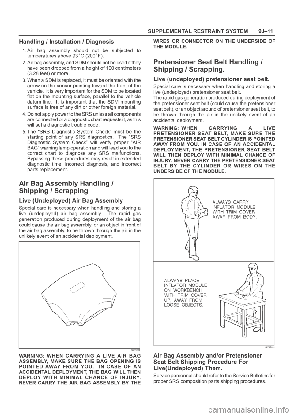
Special care is necessary when handling and storing a
live (undeployed) air bag assembly. The rapid gas
generation produced during deployment of the air bag
could cause the air bag assembly, or an object in front of
the air bag assembly, to be thrown through the air in the
unlikely event of an accidental deployment.
827RV004
WARNING: WHEN CARRYING A LIVE AIR BAG
ASSEMBLY, MAKE SURE THE BAG OPENING IS
POINTED AWAY FROM YOU. IN CASE OF AN
ACCIDENTAL DEPLOYMENT, THE BAG WILL THEN
DEPLOY WITH MINIMAL CHANCE OF INJURY.
NEVER CARRY THE AIR BAG ASSEMBLY BY THEWIRES OR CONNECTOR ON THE UNDERSIDE OF
THE MODULE.
Pretensioner Seat Belt Handling /
Shipping / Scrapping.
Live (undeployed) pretensioner seat belt.
Special care is necessary when handling and storing a
live (undeployed) pretensioner seat belt.
The rapid gas generation produced during deployment of
the pretensioner seat belt (could cause the pretensioner
seat belt), or an object around of pretensioner seat belt, to
be thrown through the air in the unlikely event of an
accidental deployment.
WARNING: WHEN CARRYING A LIVE
PRETENSIONER SEAT BELT, MAKE SURE THE
PRETENSIONER SEAT BELT CYLINDER IS POINTED
AWAY FROM YOU. IN CASE OF AN ACCIDENTAL
DEPLOYMENT, THE PRETENSIONER SEAT BELT
WILL THEN DEPLOY WITH MINIMAL CHANCE OF
INJURY. NEVER CARRY THE PRETENSIONER SEAT
BELT BY THE CYLINDER OR WIRES ON THE
UNDERSIDE OF THE MODULE.
827RS044
Air Bag Assembly and/or Pretensioner
Seat Belt Shipping Procedure For
Live(Undeployed) Them.
Service personnel should refer to the Service Bulletins for
proper SRS composition parts shipping procedures.
Page 3467 of 6000
SUPPLEMENTAL RESTRAINT SYSTEM 9J–30
Service Precautions for SRS
Component Service
CAUTION: When fasteners are removed, always
reinstall them at the same location from which they
were removed. If a fastener needs to be replaced, use
the correct part number fastener for that application.
If the correct part number fastener is not available, a
fastener of equal size and strength (or stronger) may
be used. fasteners that are not reused, and those
requiring thread locking compound will be called
out. The correct torque value must be used when
installing fasteners that require it. If the above
conditions are not followed, parts or system damage
could result.
WARNING: WHEN PERFORMING SERVICE ON OR
AROUND SRS COMPONENTS OR SRS WIRING,
FOLLOW THE PROCEDURES LISTED BELOW TO
TEMPORARILY DISABLE THE SRS. FAILURE TO
FOLLOW PROCEDURES COULD RESULT IN
POSSIBLE AIR BAG DEPLOYMENT, PERSONAL
INJURY OR OTHERWISE UNNEEDED SRS REPAIRS.
The SDM in Driver–Passenger SRS can maintain
sufficient voltage to cause a deployment for up to 15
seconds after the ignition switch is turned “OFF,” the
battery is disconnected, or the fuse powering the SDM is
removed.
Many of the service procedures require removal of the
“C–21” fuse, and disconnection of the air bag assembly
from the deployment loop to avoid an accidental
deployment. If the air bag assembly is disconnected from
the deployment loop as noted in the “Disabling the SRS”
procedure that follows, service can begin immediately
without waiting for the 15 second time period to expire.
Disabling The SRS
Removal
Turn the ignition switch to “OFF” and turn the steering
wheel so that the vehicle’s wheels are pointing straight
ahead.
1. Remove SRS fuse “C–21” from left dash side lower
fuse block or disconnect battery.
2. Disconnect yellow 2–pin connector at the base of
steering column.
3 . R e m o v e g l o v e b o x a s s e m b l y ; R e f e r t o “ P a s s e n g e r a i r
bag assembly replacement” in this section.
4. Disconnect passenger air bag assembly yellow 2–pin
connector behind the glove box assembly.
CAUTION: W i t h t h e “ C – 2 1 ” f u s e r e m o v e d a n d
ignition switch “ON,” the “AIR BAG” warning lamp
will be “ON.” This is normal operation and does not
indicate an SRS malfunction.
Enabling The SRS
Installation
Turn ignition switch to “LOCK” and remove key.
1. Connect yellow 2–pin connector passenger air bag
assembly.2. Install glove box assembly. Refer to “Passenger Air
Bag Assembly Replacement” in this section.
3. Connect yellow 2–pin connector at the base of the
steering column.
4. Install “AIR BAG” fuse “C–21” to left dash side lower
fuse block or connect battery.
Turn ignition switch to “ON” and verify that the “AIR BAG”
warning lamp turn on 3.5 seconds and then turns “OFF.” If
it does not operate as described, perform the “SRS
Diagnostic System Check” in this section.
Handling / Installation / Diagnosis
1. Air bag assembly should not be subjected to
temperatures above 93
C (200F).
2. Air bag assembly, and SDM should not be used if they
have been dropped from a height of 100 centimeters
(3.28 feet) or more.
3. When a SDM is replaced, it must be oriented with the
arrow on the SDM pointing toward the front of the
vehicle. It is very important for the SDM to be located
flat on the mounting surface, parallel to the vehicle
datum line. It is important that the SDM mounting
surface is free of any dirt or other foreign material.
4. Do not apply power to the SRS unless all components
are connected or a diagnostic chart requests it, as
this will set a diagnostic trouble code.
5. The “SRS Diagnostic System Check” must be the
starting point of any SRS diagnostics. The “SRS
Diagnostic System Check” will verify proper “AIR
BAG” warning lamp operation and will lead you to the
correct chart to diagnose any SRS malfunctions.
Bypassing these procedures may result in extended
diagnostic time, incorrect diagnosis, and incorrect
parts replacements.
Inspections Required After An Accident
CAUTION: C e r t a i n S R S c o m p o n e n t s m u s t b e
replaced after a frontal crash involving air bag
deployment.
In all types of accidents regardless of “Air Bag”
deployment, visually inspect all of the following
components and replace as required:
— Driver air bag assembly
— Passenger air bag assembly
— Driver pretensioner assembly
— Passenger pretensioner assembly
— Steering wheel
— SRS coil assembly
— Steering column
— Knee bolster and instrument panel mounting
attachments
— Driver seat and belt
— Passenger seat and belt
—SDM
SDM always should be checked according to “SDM
Replacement Guidelines.”
Page 3470 of 6000
SUPPLEMENTAL RESTRAINT SYSTEM9J–33
Sensing And Diagnostic Module (SDM)
Service Precautions
WARNING: DURING SERVICE PROCEDURES, BE
VERY CAREFUL WHEN HANDLING SDM. NEVER
STRIKE OR JAR SDM. UNDER SOME
CIRCUMSTANCES, IT COULD CAUSE
DEPLOYMENT AND RESULT IN PERSONAL INJURY
OR IMPROPER OPERATION OF THE
SUPPLEMENTAL RESTRAINT SYSTEM (SRS) . SDM
MOUNTING BRACKET BOLTS MUST BE
CAREFULLY TORQUED TO ASSURE PROPER
OPERATION. NEVER POWER UP THE SRS WHEN
SDM IS NOT RIGIDLY ATTACHED TO THE VEHICLE.
THE SDM COULD BE ACTIVATED WHEN POWERED
WHILE NOT RIGIDLY ATTACHED TO THE VEHICLE
WHICH COULD CAUSE DEPLOYMENT AND RESULT
IN PERSONAL INJURY.
WARNING: PROPER OPERATION OF THE SENSING
AND DIAGNOSTIC MODULE (SDM) REQUIRES THE
SDM TO BE RIGIDLY ATTACHED TO THE VEHICLE
STRUCTURE AND THAT THE ARROW ON THE
SENSOR BE POINTING TOWARD THE FRONT OF
THE VEHICLE.
SDM is specifically calibrated and is keyed to the SDM
location SRS wiring harness. Caution should be used to
ensure proper location of the SDM. The keying of the
SDM to its location and wiring harness connectors should
never be modified in the field.
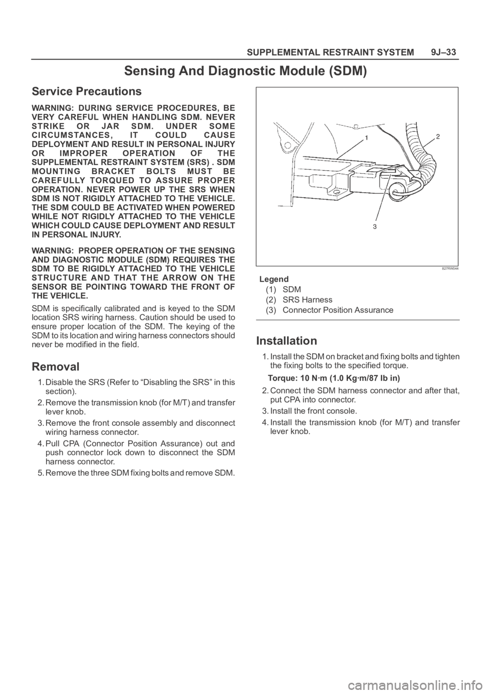
Removal
1. Disable the SRS (Refer to “Disabling the SRS” in this
section).
2. Remove the transmission knob (for M/T) and transfer
lever knob.
3. Remove the front console assembly and disconnect
wiring harness connector.
4. Pull CPA (Connector Position Assurance) out and
push connector lock down to disconnect the SDM
harness connector.
5. Remove the three SDM fixing bolts and remove SDM.
827RW044
Legend
(1) SDM
(2) SRS Harness
(3) Connector Position Assurance
Installation
1. Install the SDM on bracket and fixing bolts and tighten
the fixing bolts to the specified torque.
Torque: 10 Nꞏm (1.0 Kgꞏm/87 Ib in)
2. Connect the SDM harness connector and after that,
put CPA into connector.
3. Install the front console.
4. Install the transmission knob (for M/T) and transfer
lever knob.
Page 3494 of 6000
9J1–7
RESTRAINT CONTROL SYSTEM
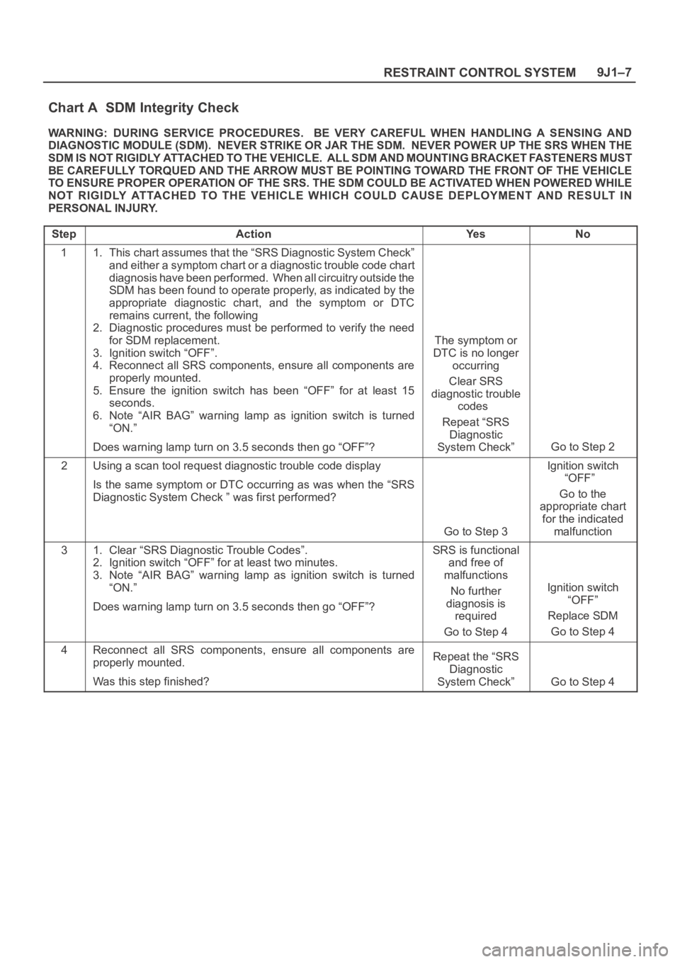
Chart A SDM Integrity Check
WARNING: DURING SERVICE PROCEDURES. BE VERY CAREFUL WHEN HANDLING A SENSING AND
DIAGNOSTIC MODULE (SDM). NEVER STRIKE OR JAR THE SDM. NEVER POWER UP THE SRS WHEN THE
S D M I S N O T R I G I D LY AT TA C H E D T O T H E V E H I C L E . A L L S D M A N D M O U N T ING BRACKET FASTENERS MUST
BE CAREFULLY TORQUED AND THE ARROW MUST BE POINTING TOWARD THE FRONT OF THE VEHICLE
TO ENSURE PROPER OPERATION OF THE SRS. THE SDM COULD BE ACTIVATED WHEN POWERED WHILE
NOT RIGIDLY ATTACHED TO THE VEHICLE WHICH COULD CAUSE DEPLOYMENT AND RESULT IN
PERSONAL INJURY.
Step
ActionYe sNo
11. This chart assumes that the “SRS Diagnostic System Check”
and either a symptom chart or a diagnostic trouble code chart
diagnosis have been performed. When all circuitry outside the
SDM has been found to operate properly, as indicated by the
appropriate diagnostic chart, and the symptom or DTC
remains current, the following
2. Diagnostic procedures must be performed to verify the need
for SDM replacement.
3. Ignition switch “OFF”.
4. Reconnect all SRS components, ensure all components are
properly mounted.
5. Ensure the ignition switch has been “OFF” for at least 15
seconds.
6. Note “AIR BAG” warning lamp as ignition switch is turned
“ON.”
Does warning lamp turn on 3.5 seconds then go “OFF”?
The symptom or
DTC is no longer
occurring
Clear SRS
diagnostic trouble
codes
Repeat “SRS
Diagnostic
System Check”
Go to Step 2
2Using a scan tool request diagnostic trouble code display
Is the same symptom or DTC occurring as was when the “SRS
Diagnostic System Check ” was first performed?
Go to Step 3
Ignition switch
“OFF”
Go to the
appropriate chart
for the indicated
malfunction
31. Clear “SRS Diagnostic Trouble Codes”.
2. Ignition switch “OFF” for at least two minutes.
3. Note “AIR BAG” warning lamp as ignition switch is turned
“ON.”
Does warning lamp turn on 3.5 seconds then go “OFF”?SRS is functional
and free of
malfunctions
No further
diagnosis is
required
Go to Step 4
Ignition switch
“OFF”
Replace SDM
Go to Step 4
4Reconnect all SRS components, ensure all components are
properly mounted.
Was this step finished?Repeat the “SRS
Diagnostic
System Check”
Go to Step 4
Page 3523 of 6000
RESTRAINT CONTROL SYSTEM 9J1–36
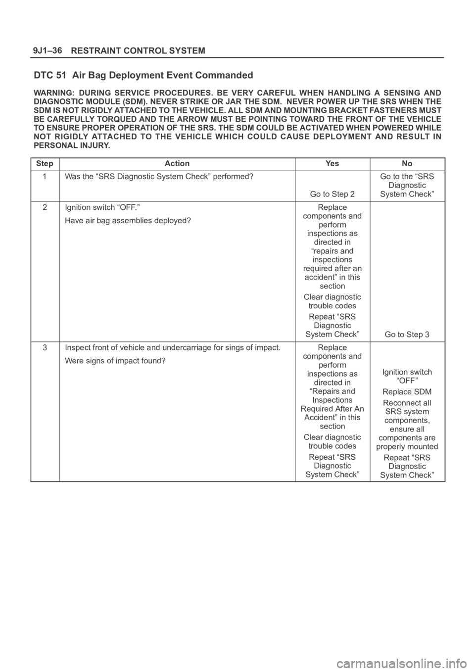
DTC 51 Air Bag Deployment Event Commanded
WARNING: DURING SERVICE PROCEDURES. BE VERY CAREFUL WHEN HANDLING A SENSING AND
DIAGNOSTIC MODULE (SDM). NEVER STRIKE OR JAR THE SDM. NEVER POWER UP THE SRS WHEN THE
SDM IS NOT RIGIDLY ATTACHED TO THE VEHICLE. ALL SDM AND MOUNTING BRACKET FASTENERS MUST
BE CAREFULLY TORQUED AND THE ARROW MUST BE POINTING TOWARD THE FRONT OF THE VEHICLE
TO ENSURE PROPER OPERATION OF THE SRS. THE SDM COULD BE ACTIVATED WHEN POWERED WHILE
NOT RIGIDLY ATTACHED TO THE VEHICLE WHICH COULD CAUSE DEPLOYMENT AND RESULT IN
PERSONAL INJURY.
Step
ActionYe sNo
1Was the “SRS Diagnostic System Check” performed?
Go to Step 2
Go to the “SRS
Diagnostic
System Check”
2Ignition switch “OFF.”
Have air bag assemblies deployed?Replace
components and
perform
inspections as
directed in
“repairs and
inspections
required after an
accident” in this
section
Clear diagnostic
trouble codes
Repeat “SRS
Diagnostic
System Check”
Go to Step 3
3Inspect front of vehicle and undercarriage for sings of impact.
Were signs of impact found?Replace
components and
perform
inspections as
directed in
“Repairs and
Inspections
Required After An
Accident” in this
section
Clear diagnostic
trouble codes
Repeat “SRS
Diagnostic
System Check”
Ignition switch
“OFF”
Replace SDM
Reconnect all
SRS system
components,
ensure all
components are
properly mounted
Repeat “SRS
Diagnostic
System Check”
Page 3525 of 6000
RESTRAINT CONTROL SYSTEM 9J1–38
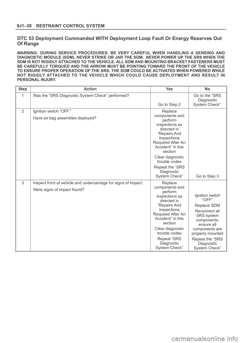
DTC 53 Deployment Commanded WITH Deployment Loop Fault Or Energy Reserves Out
Of Range
WARNING: DURING SERVICE PROCEDURES. BE VERY CAREFUL WHEN HANDLING A SENSING AND
DIAGNOSTIC MODULE (SDM). NEVER STRIKE OR JAR THE SDM. NEVER POWER UP THE SRS WHEN THE
SDM IS NOT RIGIDLY ATTACHED TO THE VEHICLE. ALL SDM AND MOUNTING BRACKET FASTENERS MUST
BE CAREFULLY TORQUED AND THE ARROW MUST BE POINTING TOWARD THE FRONT OF THE VEHICLE
TO ENSURE PROPER OPERATION OF THE SRS. THE SDM COULD BE ACTIVATED WHEN POWERED WHILE
NOT RIGIDLY ATTACHED TO THE VEHICLE WHICH COULD CAUSE DEPLOYMENT AND RESULT IN
PERSONAL INJURY.
Step
ActionYe sNo
1Was the “SRS Diagnostic System Check” performed?
Go to Step 2
Go to the “SRS
Diagnostic
System Check”
2Ignition switch “OFF.”
Have air bag assembles deployed?Replace
components and
perform
inspections as
directed in
“Repairs And
Inspections
Required After An
Accident” in this
section
Clear diagnostic
trouble codes
Repeat the “SRS
Diagnostic
System Check”
Go to Step 3
3Inspect front of vehicle and undercarriage for signs of impact.
Were signs of impact found?Replace
components and
perform
inspections as
directed in
“Repairs And
Inspections
Required After An
Accident” in this
section
Clear diagnostic
trouble codes
Repeat “SRS
Diagnostic
System Check”
Ignition switch
“OFF”
Replace SDM
Reconnect all
SRS system
components,
ensure all
components are
properly mounted
Repeat the “SRS
Diagnostic
System Check”