1998 OPEL FRONTERA tow
[x] Cancel search: towPage 2221 of 6000
7A–67 AUTOMATIC TRANSMISSION (4L30–E)
Sprag Unit
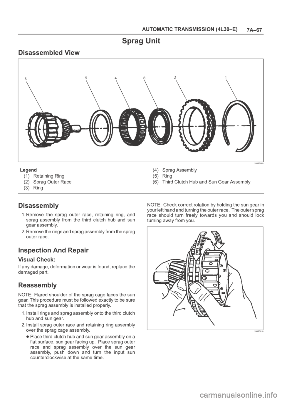
Disassembled View
248RS009
Legend
(1) Retaining Ring
(2) Sprag Outer Race
(3) Ring(4) Sprag Assembly
(5) Ring
(6) Third Clutch Hub and Sun Gear Assembly
Disassembly
1. Remove the sprag outer race, retaining ring, and
sprag assembly from the third clutch hub and sun
gear assembly.
2. Remove the rings and sprag assembly from the sprag
outer race.
Inspection And Repair
Visual Check:
If any damage, deformation or wear is found, replace the
damaged part.
Reassembly
NOTE: Flared shoulder of the sprag cage faces the sun
gear. This procedure must be followed exactly to be sure
that the sprag assembly is installed properly.
1. Install rings and sprag assembly onto the third clutch
hub and sun gear.
2. Install sprag outer race and retaining ring assembly
over the sprag cage assembly.
Place third clutch hub and sun gear assembly on a
flat surface, sun gear facing up. Place sprag outer
race and sprag assembly over the sun gear
assembly, push down and turn the input sun
counterclockwise at the same time. NOTE: Check correct rotation by holding the sun gear in
your left hand and turning the outer race. The outer sprag
race should turn freely towards you and should lock
turning away from you.
248RS010
Page 2223 of 6000
7A–69 AUTOMATIC TRANSMISSION (4L30–E)
Inspection And Repair
Visual Check:
If any damage, deformation or wear is found, replace the
damaged part.
Operation Check:
Shake the piston and listen for check ball movement.
Movement indicates proper check ball operation.
Replace the piston if the check ball is missing or falls out.
Reassembly
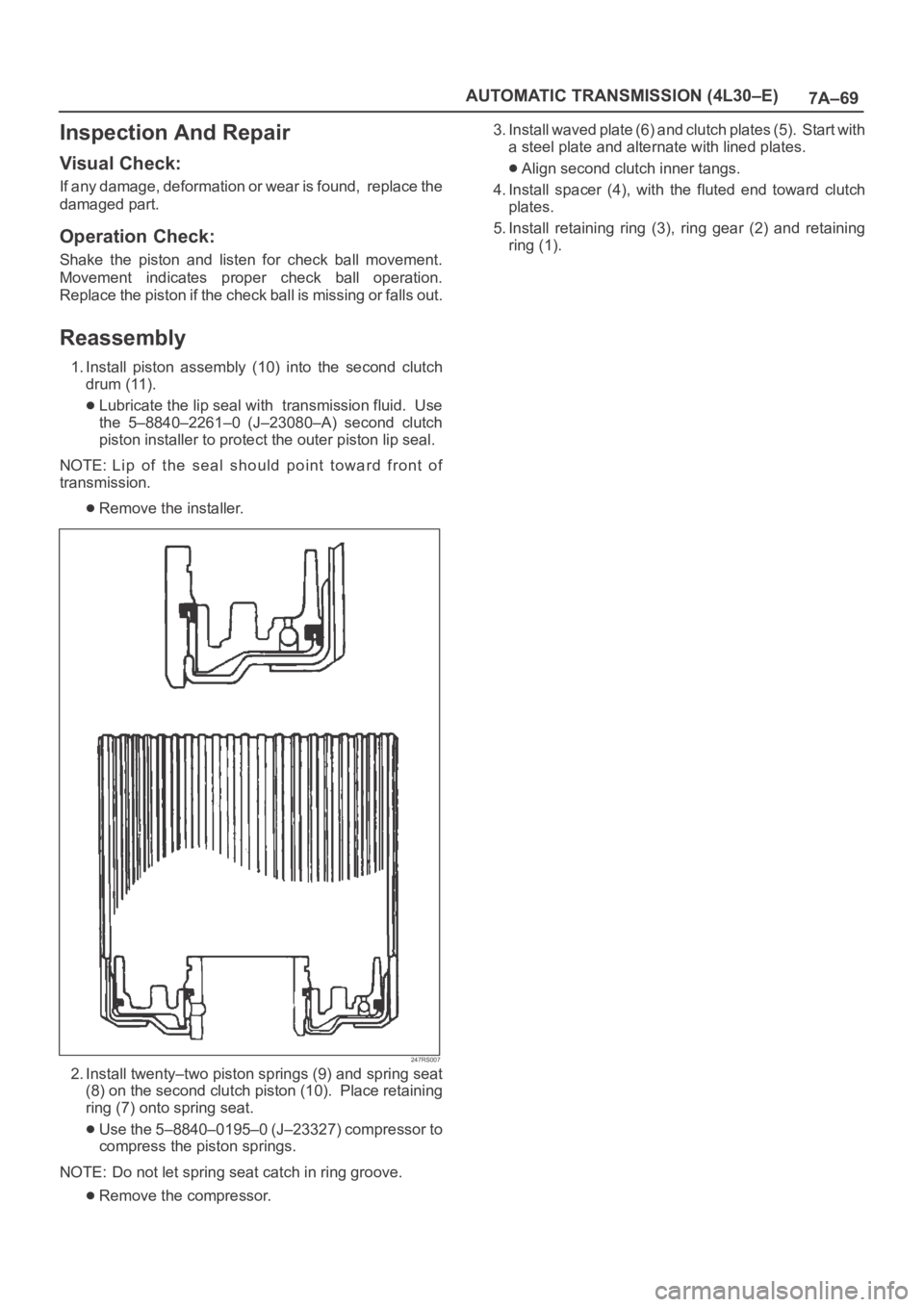
1. Install piston assembly (10) into the second clutch
drum (11).
Lubricate the lip seal with transmission fluid. Use
the 5–8840–2261–0 (J–23080–A) second clutch
piston installer to protect the outer piston lip seal.
NOTE: Lip of the seal should point toward front of
transmission.
Remove the installer.
247RS007
2. Install twenty–two piston springs (9) and spring seat
(8) on the second clutch piston (10). Place retaining
ring (7) onto spring seat.
Use the 5–8840–0195–0 (J–23327) compressor to
compress the piston springs.
NOTE: Do not let spring seat catch in ring groove.
Remove the compressor.3. Install waved plate (6) and clutch plates (5). Start with
a steel plate and alternate with lined plates.
Align second clutch inner tangs.
4. Install spacer (4), with the fluted end toward clutch
plates.
5. Install retaining ring (3), ring gear (2) and retaining
ring (1).
Page 2270 of 6000
TRANSMISSION CONTROL SYSTEM (4L30–E)7A1–25
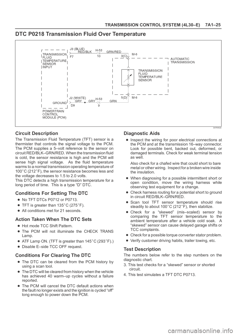
DTC P0218 Transmission Fluid Over Temperature
D07RW029
Circuit Description
The Transmission Fluid Temperature (TFT) sensor is a
thermister that controls the signal voltage to the PCM.
The PCM supplies a 5–volt reference to the sensor on
circuit RED/BLK–GRN/RED. When the transmission fluid
is cold, the sensor resistance is high and the PCM will
sense high signal voltage. As the fluid temperature
warms to a normal transmission operating temperature of
100
C (212F), the sensor resistance becomes less and
the voltage decreases to 1.5 to 2.0 volts.
This DTC detects a high transmission temperature for a
long period of time. This is a type “D” DTC.
Conditions For Setting The DTC
No TFT DTCs P0712 or P0713.
TFT is greater than 135C (275F).
All conditions met for 21 seconds.
Action Taken When The DTC Sets
Hot mode TCC Shift Pattern.
The PCM will not illuminate the CHECK TRANS
Lamp.
ATF Lamp ON. (TFT is greater than 145C (293F).)
Disable E–side TCC OFF request.
Conditions For Clearing The DTC
The DTC can be cleared from the PCM history by
using a scan tool.
The DTC will be cleared from history when the vehicle
has achieved 40 warm–up cycles without a failure
reported.
The PCM will cancel the DTC default actions when
the fault no longer exists and the ignition is cycled “off”
long enough to power down the PCM.
Diagnostic Aids
Inspect the wiring for poor electrical connections at
the PCM and at the transmission 16–way connector.
Look for possible bent, backed out, deformed, or
damaged terminals. Check for weak terminal tension
as well.
Also check for a chafed wire that could short to bare
metal or other wiring. Inspect for a broken wire inside
the insulation.
When diagnosing for a possible intermittent short or
open condition, move the wiring harness while
observing test equipment for a change.
Check harness routing for a potential short to ground
in circuit RED/BLK–GRN/RED.
Scan tool TFT sensor temperature should rise
steadily to about 100
C (212F), then stabilize.
Check for a “skewed” (mis–scaled) sensor by
comparing the TFT sensor temperature to the
ambient temperature after a vehicle cold soak. A
“skewed” sensor can cause delayed garage shifts or
TCC complaints.
Check for a possible torque converter stator problem.
Verify customer driving habits, trailer towing, etc.
Test Description
The numbers below refer to the step numbers on the
diagnostic chart.
3. This test checks for a “skewed” sensor or shorted
circuit.
4. This test simulates a TFT DTC P0713.
Page 2281 of 6000
7A1–36
TRANSMISSION CONTROL SYSTEM (4L30–E)
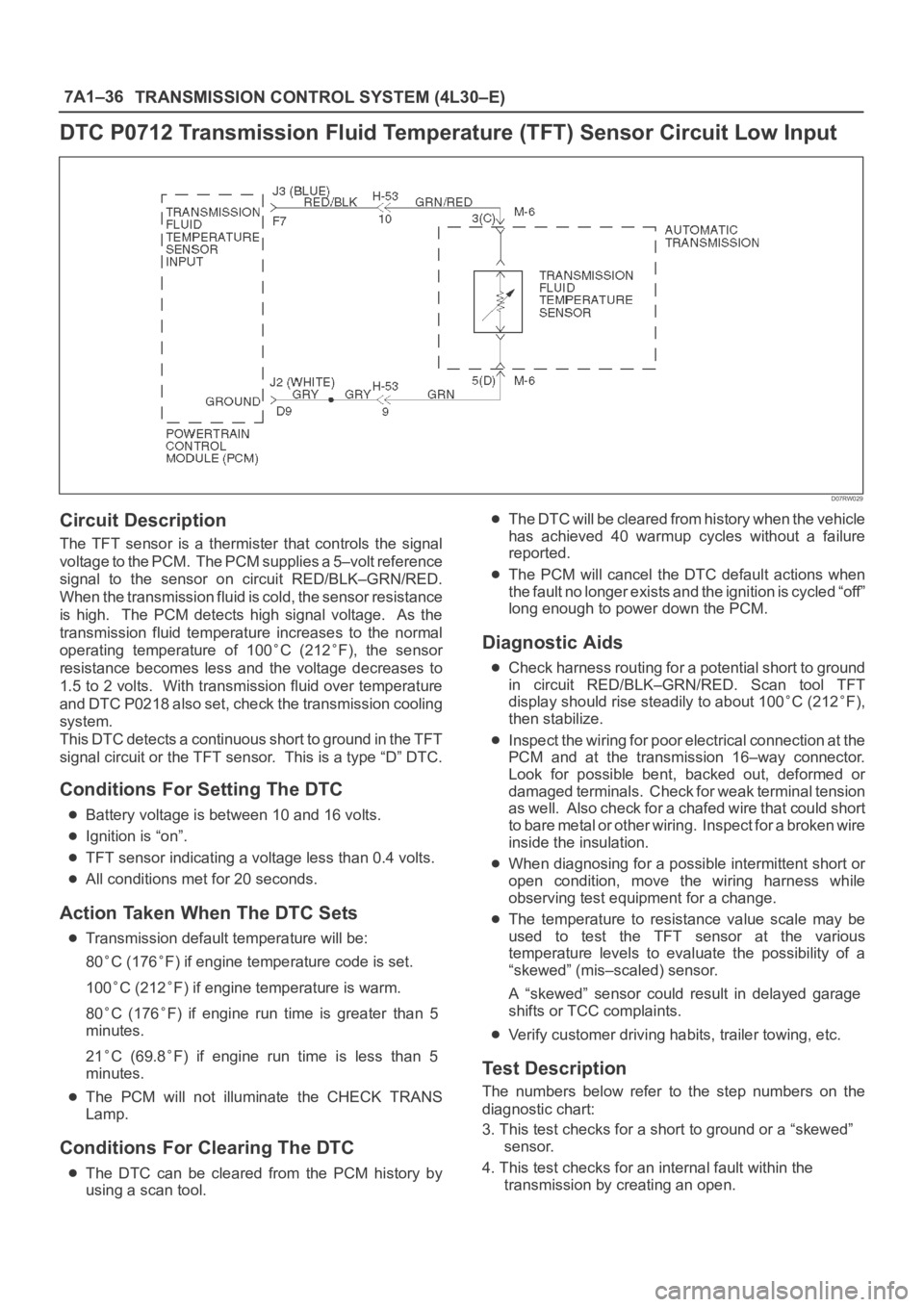
DTC P0712 Transmission Fluid Temperature (TFT) Sensor Circuit Low Input
D07RW029
Circuit Description
The TFT sensor is a thermister that controls the signal
voltage to the PCM. The PCM supplies a 5–volt reference
signal to the sensor on circuit RED/BLK–GRN/RED.
When the transmission fluid is cold, the sensor resistance
is high. The PCM detects high signal voltage. As the
transmission fluid temperature increases to the normal
operating temperature of 100
C (212F), the sensor
resistance becomes less and the voltage decreases to
1.5 to 2 volts. With transmission fluid over temperature
and DTC P0218 also set, check the transmission cooling
system.
This DTC detects a continuous short to ground in the TFT
signal circuit or the TFT sensor. This is a type “D” DTC.
Conditions For Setting The DTC
Battery voltage is between 10 and 16 volts.
Ignition is “on”.
TFT sensor indicating a voltage less than 0.4 volts.
All conditions met for 20 seconds.
Action Taken When The DTC Sets
Transmission default temperature will be:
80
C (176F) if engine temperature code is set.
100
C (212F) if engine temperature is warm.
80
C (176F) if engine run time is greater than 5
minutes.
21
C (69.8F) if engine run time is less than 5
minutes.
The PCM will not illuminate the CHECK TRANS
Lamp.
Conditions For Clearing The DTC
The DTC can be cleared from the PCM history by
using a scan tool.
The DTC will be cleared from history when the vehicle
has achieved 40 warmup cycles without a failure
reported.
The PCM will cancel the DTC default actions when
the fault no longer exists and the ignition is cycled “off”
long enough to power down the PCM.
Diagnostic Aids
Check harness routing for a potential short to ground
in circuit RED/BLK–GRN/RED. Scan tool TFT
display should rise steadily to about 100
C (212F),
then stabilize.
Inspect the wiring for poor electrical connection at the
PCM and at the transmission 16–way connector.
Look for possible bent, backed out, deformed or
damaged terminals. Check for weak terminal tension
as we ll. A lso ch eck fo r a ch af e d w ire th at cou l d s ho r t
to bare metal or other wiring. Inspect for a broken wire
inside the insulation.
When diagnosing for a possible intermittent short or
open condition, move the wiring harness while
observing test equipment for a change.
The temperature to resistance value scale may be
used to test the TFT sensor at the various
temperature levels to evaluate the possibility of a
“skewed” (mis–scaled) sensor.
A “skewed” sensor could result in delayed garage
shifts or TCC complaints.
Verify customer driving habits, trailer towing, etc.
Test Description
The numbers below refer to the step numbers on the
diagnostic chart:
3. This test checks for a short to ground or a “skewed”
sensor.
4. This test checks for an internal fault within the
transmission by creating an open.
Page 2328 of 6000
7B–10MANUAL TRANSMISSION
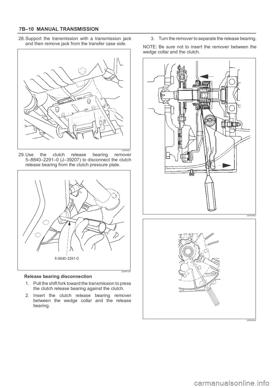
28. Support the transmission with a transmission jack
and then remove jack from the transfer case side.
220RS001
29. Use the clutch release bearing remover
5–8840–2291–0 (J–39207) to disconnect the clutch
release bearing from the clutch pressure plate.
220RW109
Release bearing disconnection
1. Pull the shift fork toward the transmission to press
the clutch release bearing against the clutch.
2. Insert the clutch release bearing remover
between the wedge collar and the release
bearing.3. Turn the remover to separate the release bearing.
NOTE: Be sure not to insert the remover between the
wedge collar and the clutch.
220RW063
220RW064
Page 2331 of 6000
MANUAL TRANSMISSION7B–13
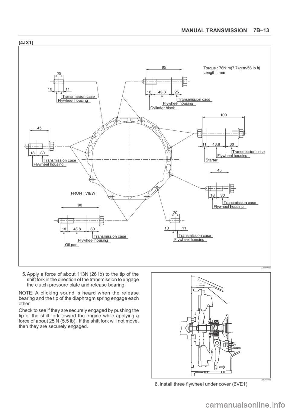
(4JX1)
225RW020
5. Apply a force of about 113N (26 Ib) to the tip of the
shift fork in the direction of the transmission to engage
the clutch pressure plate and release bearing.
NOTE: A clicking sound is heard when the release
bearing and the tip of the diaphragm spring engage each
other.
Check to see if they are securely engaged by pushing the
tip of the shift fork toward the engine while applying a
force of about 25 N (5.5 lb). If the shift fork will not move,
then they are securely engaged.
220RS006
6. Install three flywheel under cover (6VE1).
Page 2359 of 6000
MANUAL TRANSMISSION7B–41
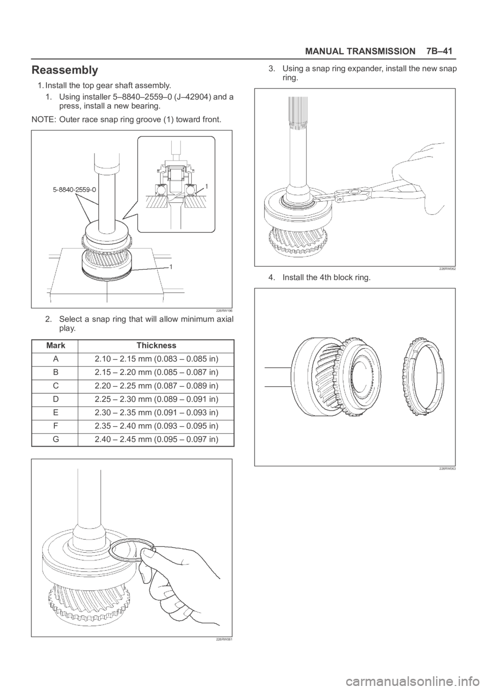
Reassembly
1. Install the top gear shaft assembly.
1. Using installer 5–8840–2559–0 (J–42904) and a
press, install a new bearing.
NOTE: Outer race snap ring groove (1) toward front.
226RW196
2. Select a snap ring that will allow minimum axial
play.
Mark
Thickness
A2.10 – 2.15 mm (0.083 – 0.085 in)
B2.15 – 2.20 mm (0.085 – 0.087 in)
C2.20 – 2.25 mm (0.087 – 0.089 in)
D2.25 – 2.30 mm (0.089 – 0.091 in)
E2.30 – 2.35 mm (0.091 – 0.093 in)
F2.35 – 2.40 mm (0.093 – 0.095 in)
G2.40 – 2.45 mm (0.095 – 0.097 in)
226RW061
3. Using a snap ring expander, install the new snap
ring.
226RW062
4. Install the 4th block ring.
226RW063
Page 2367 of 6000
MANUAL TRANSMISSION7B–49
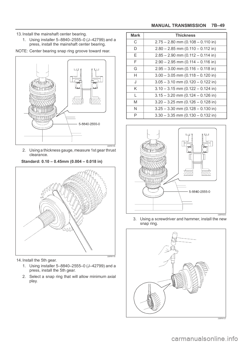
13. Install the mainshaft center bearing.
1. Using installer 5–8840–2555–0 (J–42799) and a
press, install the mainshaft center bearing.
NOTE: Center bearing snap ring groove toward rear.
226RW195
2. Using a thickness gauge, measure 1st gear thrust
clearance.
Standard: 0.10 – 0.45mm (0.004 – 0.018 in)
226RW118
14. Install the 5th gear.
1. Using installer 5–8840–2555–0 (J–42799) and a
press, install the 5th gear.
2. Select a snap ring that will allow minimum axial
play.Mark
Thickness
C2.75 – 2.80 mm (0.108 – 0.110 in)
D2.80–2.85mm (0.110–0.112in)
E2.85–2.90mm (0.112–0.114in)
F2.90–2.95mm (0.114–0.116in)
G2.95–3.00mm (0.116–0.118in)
H3.00 – 3.05 mm (0.118 – 0.120 in)
J3.05–3.10mm (0.120–0.122in)
K3.10–3.15mm (0.122–0.124in)
L3.15–3.20mm (0.124–0.126in)
M3.20–3.25mm (0.126–0.128in)
N3.25–3.30mm (0.128–0.130in)
P3.30–3.35mm (0.130–0.132in)
226RW203
3. Using a screwdriver and hammer, install the new
snap ring.
226RW127