1998 OPEL FRONTERA tow
[x] Cancel search: towPage 1082 of 6000
ENGINE ELECTRICAL6D1–3
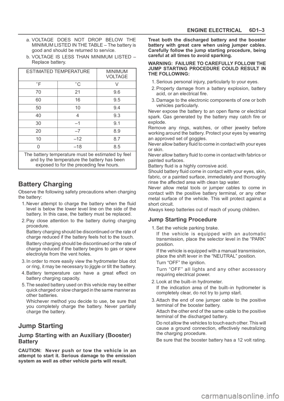
a. VOLTAGE DOES NOT DROP BELOW THE
MINIMUM LISTED IN THE TABLE – The battery is
good and should be returned to service.
b. VOLTAGE IS LESS THAN MINIMUM LISTED –
Replace battery.
ESTIMATED TEMPERATURE
MINIMUM
VOLTAGE
FCV
70219.6
60169.5
50109.4
4049.3
30–19.1
20–78.9
10–128.7
0–188.5
The battery temperature must be estimated by feel
and by the temperature the battery has been
exposed to for the preceding few hours.
Battery Charging
Observe the following safety precautions when charging
the battery:
1. Never attempt to charge the battery when the fluid
level is below the lower level line on the side of the
battery. In this case, the battery must be replaced.
2. Pay close attention to the battery during charging
procedure.
Battery charging should be discontinued or the rate of
charge reduced if the battery feels hot to the touch.
Battery charging should be discontinued or the rate of
charge reduced if the battery begins to gas or spew
electrolyte from the vent holes.
3. In order to more easily view the hydrometer blue dot
or ring, it may be necessary to jiggle or tilt the battery.
4. Battery temperature can have a great effect on
battery charging capacity.
5. The sealed battery used on this vehicle may be either
quick charged or slow charged in the same manner as
other batteries.
Whichever method you decide to use, be sure that
you completely charge the battery. Never partially
charge the battery.
Jump Starting
Jump Starting with an Auxiliary (Booster)
Battery
CAUTION: Never push or tow the vehicle in an
attempt to start it. Serious damage to the emission
system as well as other vehicle parts will result.Treat both the discharged battery and the booster
battery with great care when using jumper cables.
Carefully follow the jump starting procedure, being
careful at all times to avoid sparking.
WARNING: FAILURE TO CAREFULLY FOLLOW THE
JUMP STARTING PROCEDURE COULD RESULT IN
THE FOLLOWING:
1. Serious personal injury, particularly to your eyes.
2. Property damage from a battery explosion, battery
acid, or an electrical fire.
3. Damage to the electronic components of one or both
vehicles particularly.
Never expose the battery to an open flame or electrical
spark. Gas generated by the battery may catch fire or
explode.
Remove any rings, watches, or other jewelry before
working around the battery. Protect your eyes by wearing
an approved set of goggles.
Never allow battery fluid to come in contact with your eyes
or skin.
Never allow battery fluid to come in contact with fabrics or
painted surfaces.
Battery fluid is a highly corrosive acid.
Should battery fluid come in contact with your eyes, skin,
fabric, or a painted surface, immediately and thoroughly
rinse the affected area with clean tap water.
Never allow metal tools or jumper cables to come in
contact with the positive battery terminal, or any other
metal surface of the vehicle. This will protect against a
short circuit.
Always keep batteries out of reach of young children.
Jump Starting Procedure
1. Set the vehicle parking brake.
If the vehicle is equipped with an automatic
transmission, place the selector level in the “PARK”
position.
If the vehicle is equipped with a manual transmission,
place the shift lever in the “NEUTRAL” position.
Turn “OFF” the ignition.
Turn “OFF” all lights and any other accessory
requiring electrical power.
2. Look at the built–in hydrometer.
If the indication area of the built–in hydrometer is
completely clear, do not try to jump start.
3. Attach the end of one jumper cable to the positive
terminal of the booster battery.
Attach the other end of the same cable to the positive
terminal of the discharged battery.
Do not allow the vehicles to touch each other. This will
cause a ground connection, effectively neutralizing
the charging procedure.
Be sure that the booster battery has a 12 volt rating.
Page 1096 of 6000
6D3–5 STARTING AND CHARGING SYSTEM
Starter
Removal
1. Battery ground cable.
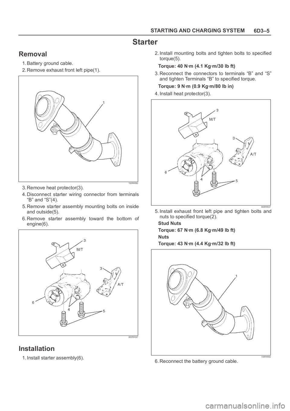
2. Remove exhaust front left pipe(1).
150RW062
3. Remove heat protector(3).
4. Disconnect starter wiring connector from terminals
“B” and “S”(4).
5. Remove starter assembly mounting bolts on inside
and outside(5).
6. Remove starter assembly toward the bottom of
engine(6).
065RW027
Installation
1. Install starter assembly(6).2. Install mounting bolts and tighten bolts to specified
torque(5).
Torque: 40 Nꞏm (4.1 Kgꞏm/30 lb ft)
3. Reconnect the connectors to terminals “B” and “S”
and tighten Terminals “B” to specified torque.
Torque: 9 Nꞏm (0.9 Kgꞏm/80 lb in)
4. Install heat protector(3).
065RW027
5. Install exhaust front left pipe and tighten bolts and
nuts to specified torque(2).
Stud Nuts
Torque: 67 Nꞏm (6.8 Kgꞏm/49 lb ft)
Nuts
Torque: 43 Nꞏm (4.4 Kgꞏm/32 lb ft)
150RW062
6. Reconnect the battery ground cable.
Page 1100 of 6000
6D3–9 STARTING AND CHARGING SYSTEM
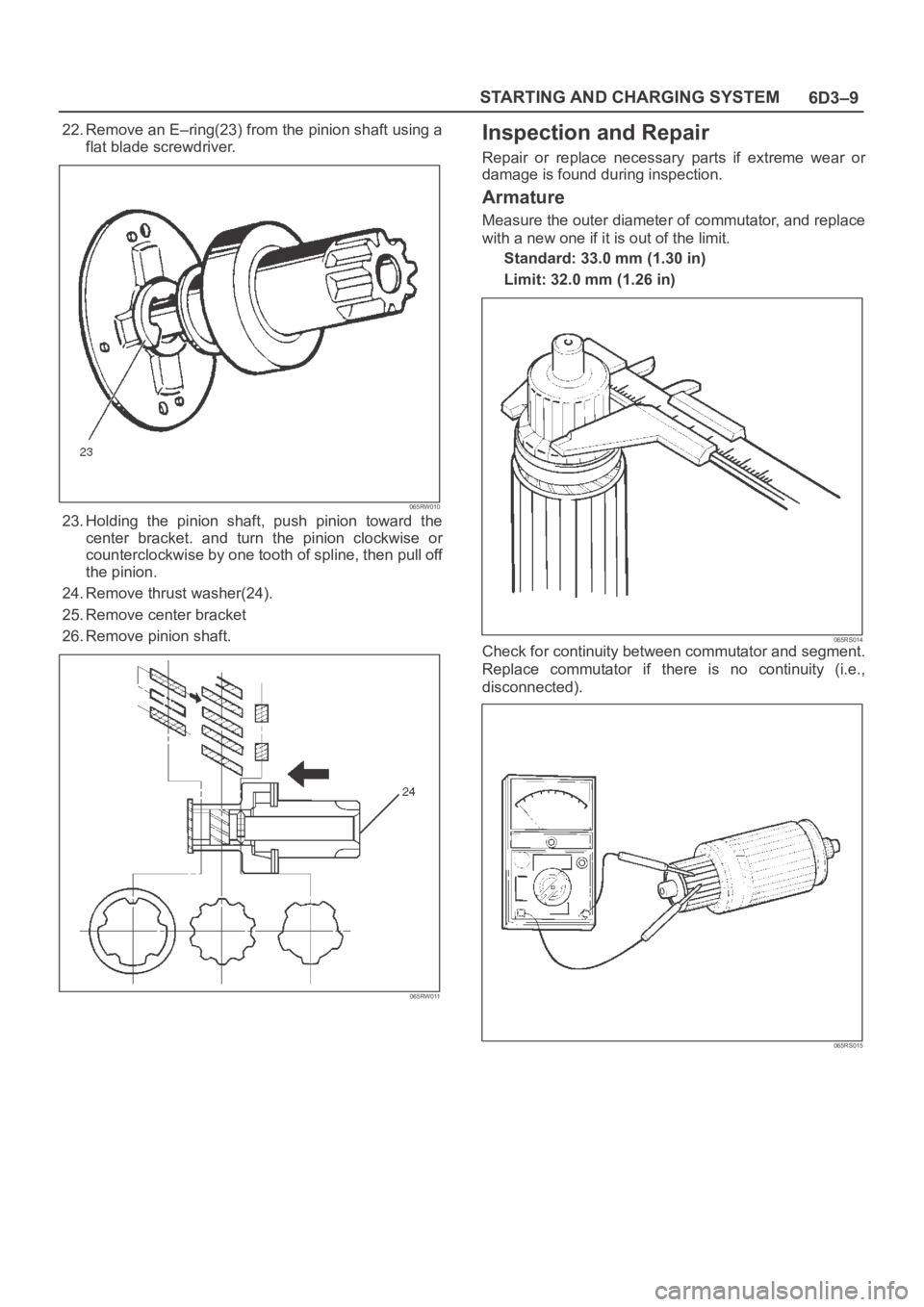
22. Remove an E–ring(23) from the pinion shaft using a
flat blade screwdriver.
065RW010
23. Holding the pinion shaft, push pinion toward the
center bracket. and turn the pinion clockwise or
counterclockwise by one tooth of spline, then pull off
the pinion.
24. Remove thrust washer(24).
25. Remove center bracket
26. Remove pinion shaft.
065RW011
Inspection and Repair
Repair or replace necessary parts if extreme wear or
damage is found during inspection.
Armature
Measure the outer diameter of commutator, and replace
with a new one if it is out of the limit.
Standard: 33.0 mm (1.30 in)
Limit: 32.0 mm (1.26 in)
065RS014Check for continuity between commutator and segment.
Replace commutator if there is no continuity (i.e.,
disconnected).
065RS015
Page 1177 of 6000
6E–60
ENGINE DRIVEABILITY AND EMISSIONS
Electronic Ignition System Diagnosis
If the engine cranks but will not run or immediately stalls,
the Engine Cranks But Will Not Start chart must be used
to determine if the failure is the ignition system or the fuel
system. If DTC P0341, or P0336 is set, the appropriate
diagnostic trouble code chart must be used for diagnosis.
If a misfire is being experienced with no DTC set, refer to
the
Symptoms section for diagnosis.
Fuel Metering System Check
Some failures of the fuel metering system will result in an
“Engine Cranks But Will Not Run” symptom. If this
condition exists, refer to the
Cranks But Will Not Run
chart. This chart will determine if the problem is caused
by the ignition system, the PCM, or the fuel pump
electrical circuit.
Refer to
Fuel System Electrical Test for the fuel system
wiring schematic.
If there is a fuel delivery problem, refer to
Fuel System
Diagnosis
, which diagnoses the fuel injectors, the fuel
pressure regulator, and the fuel pump. If a malfunction
occurs in the fuel metering system, it usually results in
either a rich HO2S signal or a lean HO2S signal. This
condition is indicated by the HO2S voltage, which causes
the PCM to change the fuel calculation (fuel injector pulse
width) based on the HO2S reading. Changes made to the
fuel calculation will be indicated by a change in the long
term fuel trim values which can be monitored with a Tech
2. Ideal long term fuel trim values are around 0%; for a
lean HO2S signal, the PCM will add fuel, resulting in a fuel
trim value above 0%. Some variations in fuel trim values
are normal because all engines are not exactly the same.
If the fuel trim values are greater than +23%, refer to
DTC
P0131, DTC P0151, DTC P0171, and DTC 1171
f o r i t e m s
which can cause a lean HO2S signal.
Idle Air Control (IAC) Valve
The Tech 2 displays the IAC pintle position in counts. A
count of “0” indicates the PCM is commanding the IAC
pintle to be driven all the way into a fully-seated position.
This is usually caused by a large vacuum leak.
The higher the number of counts, the more air is being
commanded to bypass the throttle blade. Refer to IAC
System Check in order to diagnose the IAC system.
Refer to
Rough, Unstable, or Incorrect Idle, Stalling in
Symptoms for other possible causes of idle problems.
Fuel System Pressure Test
A fuel system pressure test is part of several of the
diagnostic charts and symptom checks. To perform this
test, refer to
Fuel Systems Diagnosis.
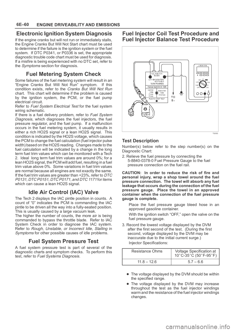
Fuel Injector Coil Test Procedure and
Fuel Injector Balance Test Procedure
T32003
Test Description
Number(s) below refer to the step number(s) on the
Diagnostic Chart:
2. Relieve the fuel pressure by connecting the
5-8840-0378-0 Fuel Pressure Gauge to the fuel
pressure connection on the fuel rail.
CAUTION: In order to reduce the risk of fire and
personal injury, wrap a shop towel around the fuel
pressure connection. The towel will absorb any fuel
leakage that occurs during the connection of the fuel
pressure gauge. Place the towel in an approved
container when the connection of the fuel pressure
gauge is complete.
Place the fuel pressure gauge bleed hose in an
approved gasoline container.
With the ignition switch “OFF,” open the valve on the
fuel pressure gauge.
3. Record the lowest voltage displayed by the DVM
after the first second of the test. (During the first
second, voltage displayed by the DVM may be
inaccurate due to the initial current surge.)
Injector Specifications:
Resistance Ohms
Voltage Specification at
10
C-35C (50F-95F)
11.8 – 12.65.7 – 6.6
The voltage displayed by the DVM should be within
the specified range.
The voltage displayed by the DVM may increase
throughout the test as the fuel injector windings
warm and the resistance of the fuel injector windings
changes.
Page 1180 of 6000
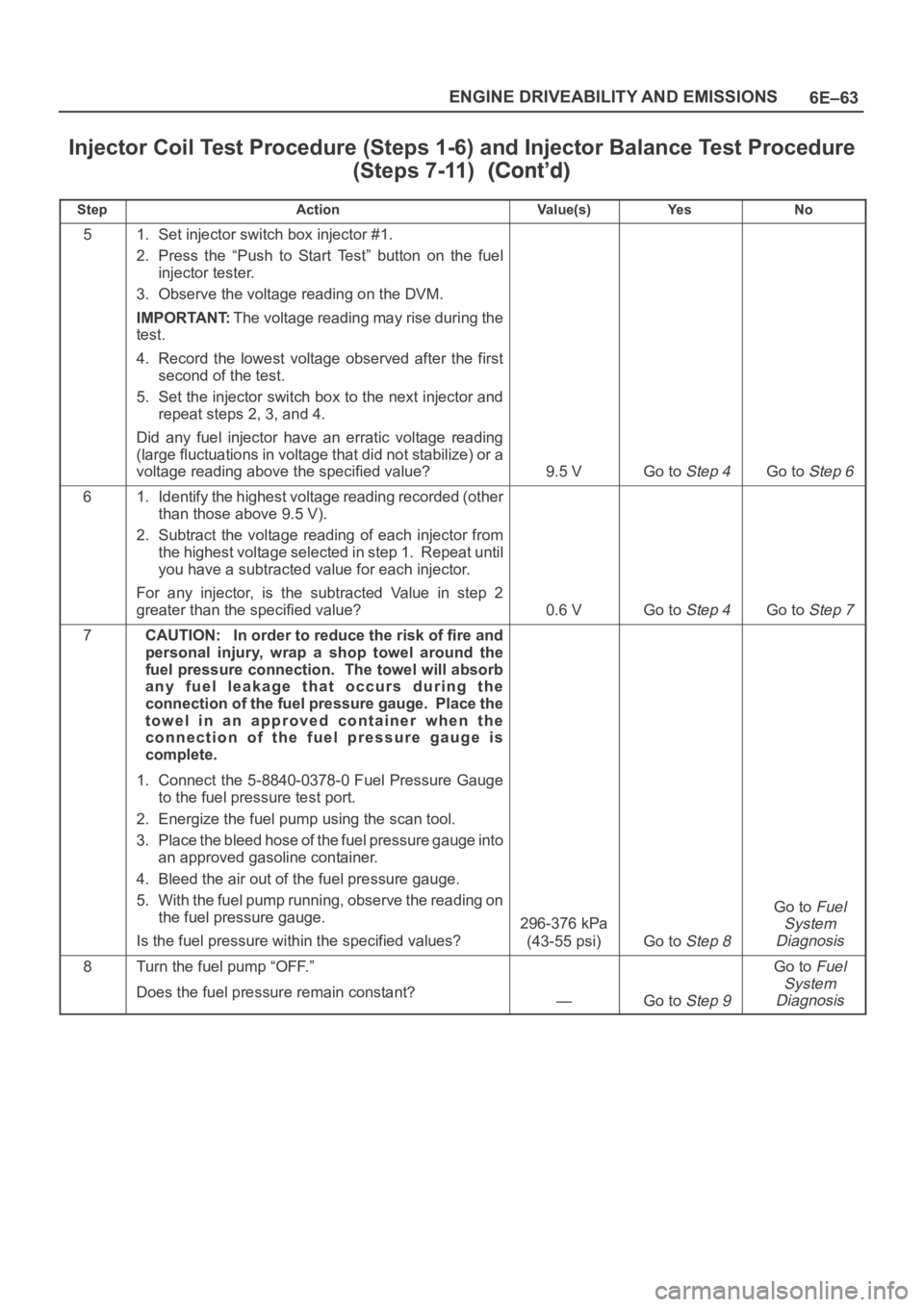
6E–63 ENGINE DRIVEABILITY AND EMISSIONS
Injector Coil Test Procedure (Steps 1-6) and Injector Balance Test Procedure
(Steps 7-11)
StepNo Ye s Va l u e ( s ) Action
51. Set injector switch box injector #1.
2. Press the “Push to Start Test” button on the fuel
injector tester.
3. Observe the voltage reading on the DVM.
IMPORTANT:The voltage reading may rise during the
test.
4. Record the lowest voltage observed after the first
second of the test.
5. Set the injector switch box to the next injector and
repeat steps 2, 3, and 4.
Did any fuel injector have an erratic voltage reading
(large fluctuations in voltage that did not stabilize) or a
voltage reading above the specified value?
9.5 VGo to Step 4Go to Step 6
61. Identify the highest voltage reading recorded (other
than those above 9.5 V).
2. Subtract the voltage reading of each injector from
the highest voltage selected in step 1. Repeat until
you have a subtracted value for each injector.
For any injector, is the subtracted Value in step 2
greater than the specified value?
0.6 VGo to Step 4Go to Step 7
7CAUTION: In order to reduce the risk of fire and
personal injury, wrap a shop towel around the
fuel pressure connection. The towel will absorb
any fuel leakage that occurs during the
connection of the fuel pressure gauge. Place the
towel in an approved container when the
connection of the fuel pressure gauge is
complete.
1. Connect the 5-8840-0378-0 Fuel Pressure Gauge
to the fuel pressure test port.
2. Energize the fuel pump using the scan tool.
3. Place the bleed hose of the fuel pressure gauge into
an approved gasoline container.
4. Bleed the air out of the fuel pressure gauge.
5. With the fuel pump running, observe the reading on
the fuel pressure gauge.
Is the fuel pressure within the specified values?
296-376 kPa
(43-55 psi)
Go to Step 8
Go to Fuel
System
Diagnosis
8Turn the fuel pump “OFF.”
Does the fuel pressure remain constant?
—Go to Step 9
Go to Fuel
System
Diagnosis
Page 1203 of 6000
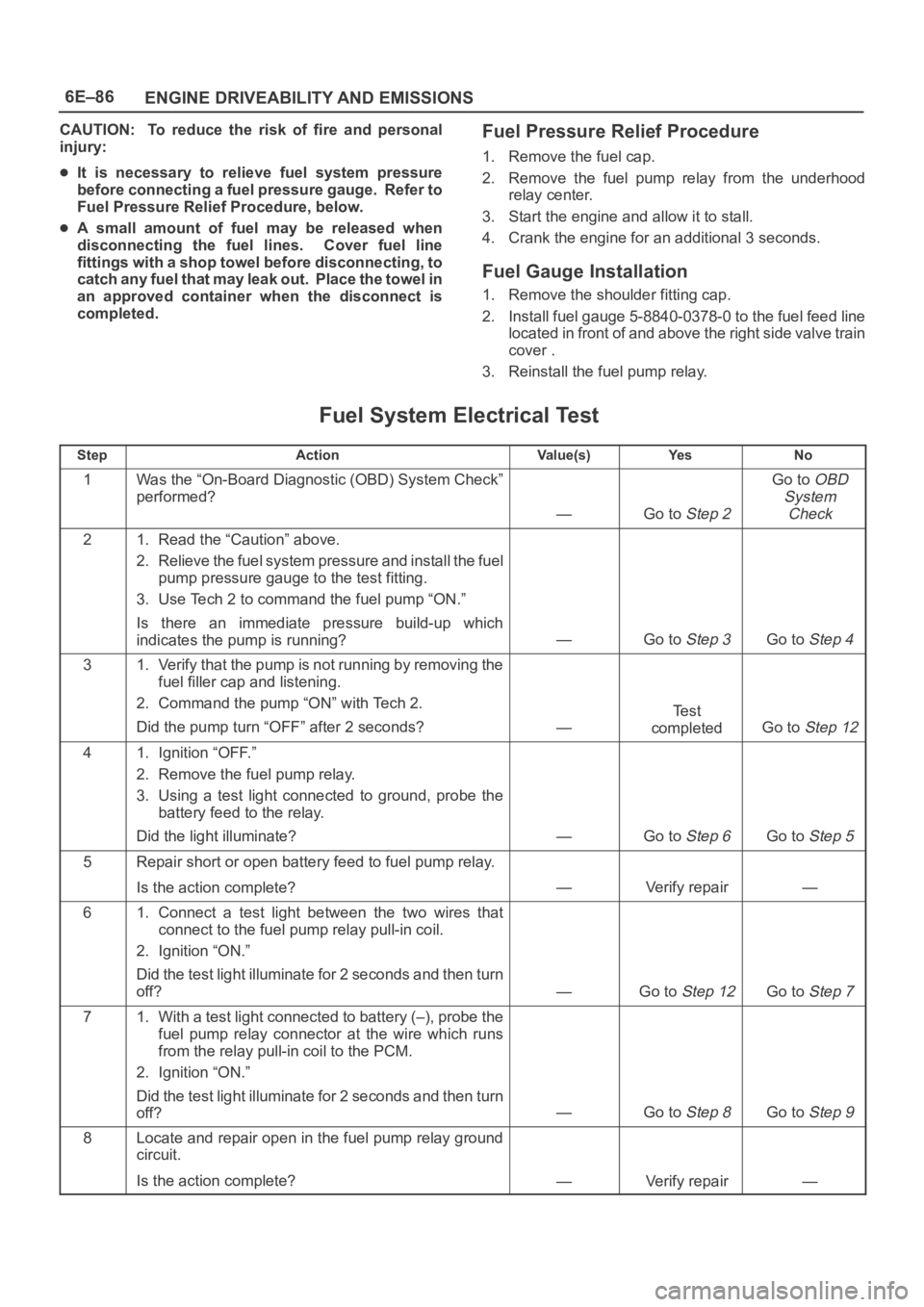
6E–86
ENGINE DRIVEABILITY AND EMISSIONS
CAUTION: To reduce the risk of fire and personal
injury:
It is necessary to relieve fuel system pressure
before connecting a fuel pressure gauge. Refer to
Fuel Pressure Relief Procedure, below.
A small amount of fuel may be released when
disconnecting the fuel lines. Cover fuel line
fittings with a shop towel before disconnecting, to
catch any fuel that may leak out. Place the towel in
an approved container when the disconnect is
completed.
Fuel Pressure Relief Procedure
1. Remove the fuel cap.
2. Remove the fuel pump relay from the underhood
relay center.
3. Start the engine and allow it to stall.
4. Crank the engine for an additional 3 seconds.
Fuel Gauge Installation
1. Remove the shoulder fitting cap.
2. Install fuel gauge 5-8840-0378-0 to the fuel feed line
located in front of and above the right side valve train
cover .
3. Reinstall the fuel pump relay.
Fuel System Electrical Test
StepActionVa l u e ( s )Ye sNo
1Was the “On-Board Diagnostic (OBD) System Check”
performed?
—Go to Step 2
Go to OBD
System
Check
21. Read the “Caution” above.
2. Relieve the fuel system pressure and install the fuel
pump pressure gauge to the test fitting.
3. Use Tech 2 to command the fuel pump “ON.”
Is there an immediate pressure build-up which
indicates the pump is running?
—Go to Step 3Go to Step 4
31. Verify that the pump is not running by removing the
fuel filler cap and listening.
2. Command the pump “ON” with Tech 2.
Did the pump turn “OFF” after 2 seconds?
—
Te s t
completed
Go to Step 12
41. Ignition “OFF.”
2. Remove the fuel pump relay.
3. Using a test light connected to ground, probe the
battery feed to the relay.
Did the light illuminate?
—Go to Step 6Go to Step 5
5Repair short or open battery feed to fuel pump relay.
Is the action complete?
—Verify repair—
61. Connect a test light between the two wires that
connect to the fuel pump relay pull-in coil.
2. Ignition “ON.”
Did the test light illuminate for 2 seconds and then turn
off?
—Go to Step 12Go to Step 7
71. With a test light connected to battery (–), probe the
fuel pump relay connector at the wire which runs
from the relay pull-in coil to the PCM.
2. Ignition “ON.”
Did the test light illuminate for 2 seconds and then turn
off?
—Go to Step 8Go to Step 9
8Locate and repair open in the fuel pump relay ground
circuit.
Is the action complete?
—Verify repair—
Page 1205 of 6000
6E–88
ENGINE DRIVEABILITY AND EMISSIONS
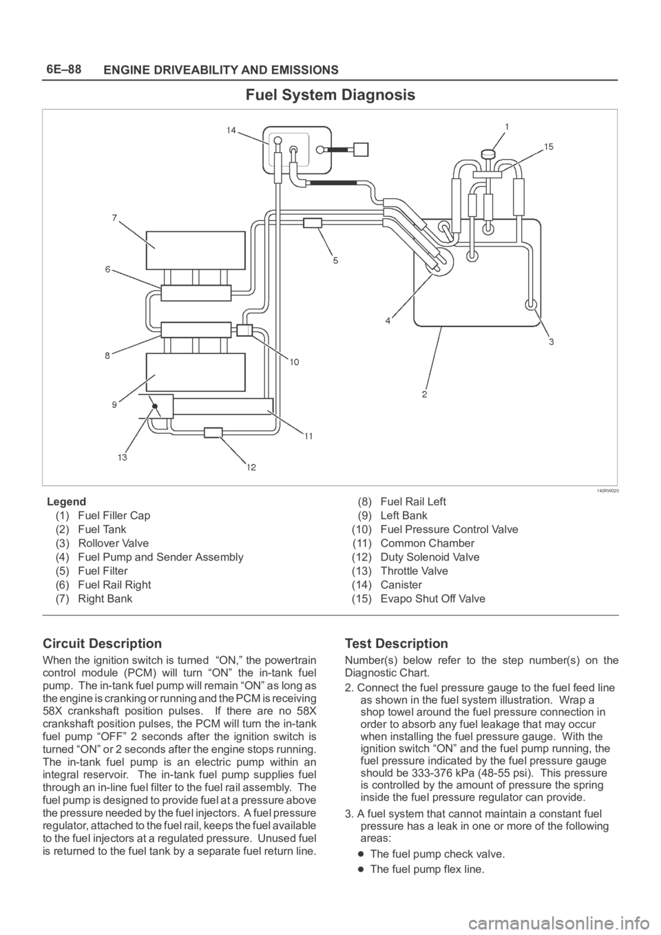
Fuel System Diagnosis
140RW020
Legend
(1) Fuel Filler Cap
(2) Fuel Tank
(3) Rollover Valve
(4) Fuel Pump and Sender Assembly
(5) Fuel Filter
(6) Fuel Rail Right
(7) Right Bank(8) Fuel Rail Left
(9) Left Bank
(10) Fuel Pressure Control Valve
(11) Common Chamber
(12) Duty Solenoid Valve
(13) Throttle Valve
(14) Canister
(15) Evapo Shut Off Valve
Circuit Description
When the ignition switch is turned “ON,” the powertrain
control module (PCM) will turn “ON” the in-tank fuel
pump. The in-tank fuel pump will remain “ON” as long as
the engine is cranking or running and the PCM is receiving
58X crankshaft position pulses. If there are no 58X
crankshaft position pulses, the PCM will turn the in-tank
fuel pump “OFF” 2 seconds after the ignition switch is
turned “ON” or 2 seconds after the engine stops running.
The in-tank fuel pump is an electric pump within an
integral reservoir. The in-tank fuel pump supplies fuel
through an in-line fuel filter to the fuel rail assembly. The
fuel pump is designed to provide fuel at a pressure above
the pressure needed by the fuel injectors. A fuel pressure
regulator, attached to the fuel rail, keeps the fuel available
to the fuel injectors at a regulated pressure. Unused fuel
is returned to the fuel tank by a separate fuel return line.
Test Description
Number(s) below refer to the step number(s) on the
Diagnostic Chart.
2. Connect the fuel pressure gauge to the fuel feed line
as shown in the fuel system illustration. Wrap a
shop towel around the fuel pressure connection in
order to absorb any fuel leakage that may occur
when installing the fuel pressure gauge. With the
ignition switch “ON” and the fuel pump running, the
fuel pressure indicated by the fuel pressure gauge
should be 333-376 kPa (48-55 psi). This pressure
is controlled by the amount of pressure the spring
inside the fuel pressure regulator can provide.
3. A fuel system that cannot maintain a constant fuel
pressure has a leak in one or more of the following
areas:
The fuel pump check valve.
The fuel pump flex line.
Page 1206 of 6000
6E–89 ENGINE DRIVEABILITY AND EMISSIONS
The valve or valve seat within the fuel pressure
regulator.
The fuel injector(s).
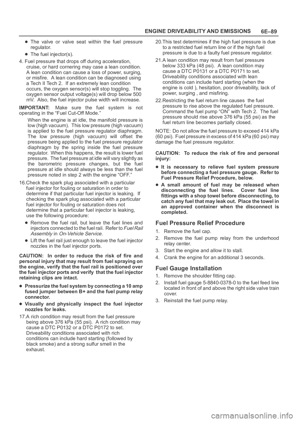
4. Fuel pressure that drops off during acceleration,
cruise, or hard cornering may case a lean condition.
A lean condition can cause a loss of power, surging,
or misfire. A lean condition can be diagnosed using
a Tech II Tech 2. If an extremely lean condition
occurs, the oxygen sensor(s) will stop toggling. The
oxygen sensor output voltage(s) will drop below 500
mV. Also, the fuel injector pulse width will increase.
IMPORTANT:Make sure the fuel system is not
operating in the “Fuel Cut-Off Mode.”
When the engine is at idle, the manifold pressure is
low (high vacuum). This low pressure (high vacuum)
is applied to the fuel pressure regulator diaphragm.
The low pressure (high vacuum) will offset the
pressure being applied to the fuel pressure regulator
diaphragm by the spring inside the fuel pressure
regulator. When this happens, the result is lower fuel
pressure. The fuel pressure at idle will vary slightly as
the barometric pressure changes, but the fuel
pressure at idle should always be less than the fuel
pressure noted in step 2 with the engine “OFF.”
16.Check the spark plug associated with a particular
fuel injector for fouling or saturation in order to
determine if that particular fuel injector is leaking. If
checking the spark plug associated with a particular
fuel injector for fouling or saturation does not
determine that a particular fuel injector is leaking,
use the following procedure:
Remove the fuel rail, but leave the fuel lines and
injectors connected to the fuel rail. Refer to
Fuel Rail
Assembly
in On-Vehicle Service.
Lift the fuel rail just enough to leave the fuel injector
nozzles in the fuel injector ports.
CAUTION: In order to reduce the risk of fire and
personal injury that may result from fuel spraying on
the engine, verify that the fuel rail is positioned over
the fuel injector ports and verify that the fuel injector
retaining clips are intact.
Pressurize the fuel system by connecting a 10 amp
fused jumper between B+ and the fuel pump relay
connector.
Visually and physically inspect the fuel injector
nozzles for leaks.
17.A rich condition may result from the fuel pressure
being above 376 kPa (55 psi). A rich condition may
cause a DTC P0132 or a DTC P0172 to set.
Driveability conditions associated with rich
conditions can include hard starting (followed by
black smoke) and a strong sulfur smell in the
exhaust.20.This test determines if the high fuel pressure is due
to a restricted fuel return line or if the high fuel
pressure is due to a faulty fuel pressure regulator.
21.A lean condition may result from fuel pressure
below 333 kPa (48 psi). A lean condition may
cause a DTC P0131 or a DTC P0171 to set.
Driveability conditions associated with lean
conditions can include hard starting (when the
engine is cold ), hesitation, poor driveability, lack of
power, surging , and misfiring.
22.Restricting the fuel return line causes the fuel
pressure to rise above the regulated fuel pressure.
Command the fuel pump “ON” with Tech 2. The fuel
pressure should rise above 376 kPa (55 psi) as the
fuel return line becomes partially closed.
NOTE: Do not allow the fuel pressure to exceed 414 kPa
( 6 0 p s i ) . F u e l p r e s s u r e i n e x c e s s o f 4 1 4 k P a ( 6 0 p s i ) m a y
damage the fuel pressure regulator.
CAUTION: To reduce the risk of fire and personal
injury:
It is necessary to relieve fuel system pressure
before connecting a fuel pressure gauge. Refer to
Fuel Pressure Relief Procedure, below.
A small amount of fuel may be released when
disconnecting the fuel lines. Cover fuel line
fittings with a shop towel before disconnecting, to
catch any fuel that may leak out. Place the towel in
an approved container when the disconnect is
completed.
Fuel Pressure Relief Procedure
1. Remove the fuel cap.
2. Remove the fuel pump relay from the underhood
relay center.
3. Start the engine and allow it to stall.
4. Crank the engine for an additional 3 seconds.
Fuel Gauge Installation
1. Remove the shoulder fitting cap.
2. Install fuel gauge 5-8840-0378-0 to the fuel feed line
located in front of and above the right side valve train
cover.
3. Reinstall the fuel pump relay.