Page 5756 of 6000

7A–67 AUTOMATIC TRANSMISSION (4L30–E)
Third Clutch
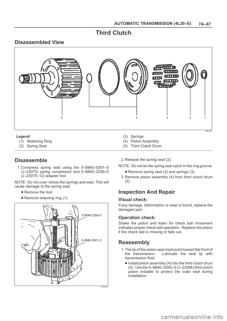
Disassembled View
248RS006
Legend
(1) Retaining Ring
(2) Spring Seat(3) Springs
(4) Piston Assembly
(5) Third Clutch Drum
Disassemble
1. Compress spring seat using the 5–8840–0501–0
(J–23075) spring compressor and 5–8840–2259–0
(J–23075–12) adapter tool.
NOTE: Do not over–stress the springs and seat. This will
cause damage to the spring seat.
Remove the tool.
Remove retaining ring (1).
248RW004
2. Release the spring seat (2).
NOTE: Do not let the spring seat catch in the ring groove.
Remove spring seat (2) and springs (3).
3. Remove piston assembly (4) from third clutch drum
(5).
Inspection And Repair
Visual check:
If any damage, deformation or wear is found, replace the
damaged part.
Operation check:
Shake the piston and listen for check ball movement
indicates proper check ball operation. Replace the piston
if the check ball is missing or falls out.
Reassembly
1. The lip of the piston seal must point toward the front of
the transmission. Lubricate the seal lip with
transmission fluid.
Install piston assembly (4) into the third clutch drum
(5). Use the 5–8840–2260–0 (J–23084) third clutch
piston installer to protect the outer seal during
installation.
Page 5758 of 6000

7A–69 AUTOMATIC TRANSMISSION (4L30–E)
Sprag Unit
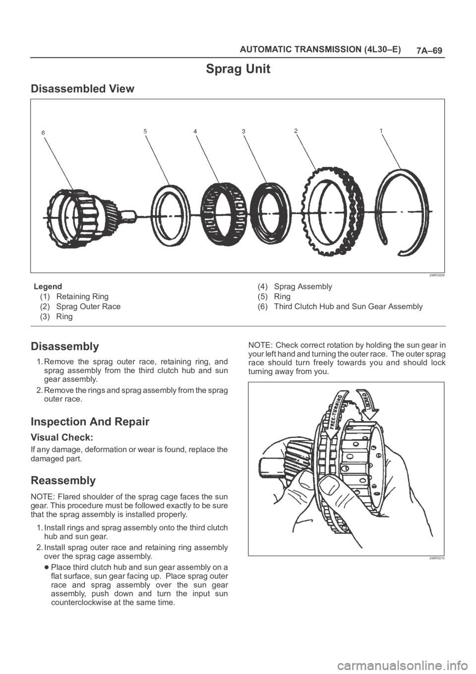
Disassembled View
248RS009
Legend
(1) Retaining Ring
(2) Sprag Outer Race
(3) Ring(4) Sprag Assembly
(5) Ring
(6) Third Clutch Hub and Sun Gear Assembly
Disassembly
1. Remove the sprag outer race, retaining ring, and
sprag assembly from the third clutch hub and sun
gear assembly.
2. Remove the rings and sprag assembly from the sprag
outer race.
Inspection And Repair
Visual Check:
If any damage, deformation or wear is found, replace the
damaged part.
Reassembly
NOTE: Flared shoulder of the sprag cage faces the sun
gear. This procedure must be followed exactly to be sure
that the sprag assembly is installed properly.
1. Install rings and sprag assembly onto the third clutch
hub and sun gear.
2. Install sprag outer race and retaining ring assembly
over the sprag cage assembly.
Place third clutch hub and sun gear assembly on a
flat surface, sun gear facing up. Place sprag outer
race and sprag assembly over the sun gear
assembly, push down and turn the input sun
counterclockwise at the same time. NOTE: Check correct rotation by holding the sun gear in
your left hand and turning the outer race. The outer sprag
race should turn freely towards you and should lock
turning away from you.
248RS010
Page 5760 of 6000

7A–71 AUTOMATIC TRANSMISSION (4L30–E)
Inspection And Repair
Visual Check:
If any damage, deformation or wear is found, replace the
damaged part.
Operation Check:
Shake the piston and listen for check ball movement.
Movement indicates proper check ball operation.
Replace the piston if the check ball is missing or falls out.
Reassembly
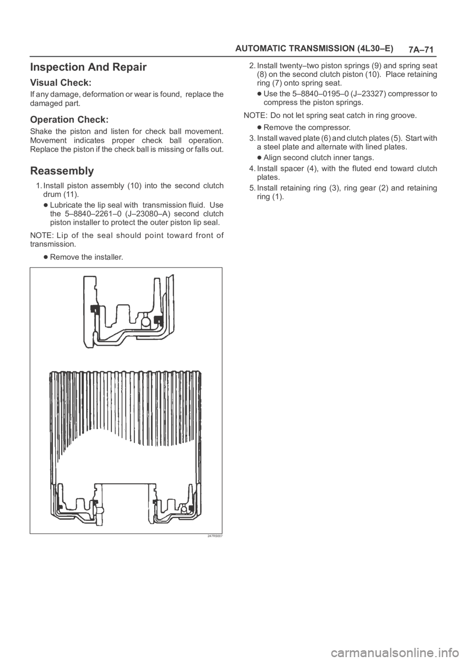
1. Install piston assembly (10) into the second clutch
drum (11).
Lubricate the lip seal with transmission fluid. Use
the 5–8840–2261–0 (J–23080–A) second clutch
piston installer to protect the outer piston lip seal.
NOTE: Lip of the seal should point toward front of
transmission.
Remove the installer.
247RS007
2. Install twenty–two piston springs (9) and spring seat
(8) on the second clutch piston (10). Place retaining
ring (7) onto spring seat.
Use the 5–8840–0195–0 (J–23327) compressor to
compress the piston springs.
NOTE: Do not let spring seat catch in ring groove.
Remove the compressor.
3. Install waved plate (6) and clutch plates (5). Start with
a steel plate and alternate with lined plates.
Align second clutch inner tangs.
4. Install spacer (4), with the fluted end toward clutch
plates.
5. Install retaining ring (3), ring gear (2) and retaining
ring (1).
Page 5869 of 6000
7A–88 AUTOMATIC TRANSMISSION (AW30-40LE)
240RY00026
022RY00001
11. Under cover and flex plate-torque converter bolt
• Remove the under cover.
• Turn the crankshaft to gain access to each bolt.
Remove the six torque cover ter fixing bolts.
NOTE:
New fixing bolts should be replaced for reassembly.
12. Rear mounting nut
• Support transmission with a jack.
• Remove two rear mounting nuts from the 3rd
crossmember.
13. 3rd crossmember
14. Oil level gauge and tube
15. Starter
• Remove the mounting bolts, and pull the star ter toward
the front of the vehicle.
Lay the star ter alongside the engine.
16. Engine-transmission bolt
• Remove engine-transmission fixing bolts.
• Disconnect the breather hose from the breather hose 3
way (W/TOD) or 2 way (WO/TOD).
17. Transmission assembly
NOTE:
Keep the oil pan positioned down.
Be careful not to let the torque converter slide out.
Page 5974 of 6000
AUTOMATIC TRANSMISSION (AW30-40LE) 7A–193
248RY00005
248RY00004
252RY00007
252RY00005
Check piston stroke of second coast brake
Place a mark on the second coast brake piston rod as
shown in the figure.
Using wire gage, measure the stroke by applying the
compressed air (4–8kg/cm
2, 57–114 psi or 392–785kPa)
as shown in the figure.
If the values are nonstandard, check for an improper
installation.
21. Race
Coat the race with petroleum jelly and install it onto the
overdrive suppor t assembly.
22. OD support
Aim the bolt and oil holes of the overdrive suppor t toward
the valve hole side, and align them with the bolt hole of the
transmission case and insert.mm (in.)
Piston stroke1.5–3.0
(0.059–0.118)
Race diameter (Reference) mm (in.)
Inside Outside
Race 36.8 (1.450) 50.9 (2.004)