1998 OPEL FRONTERA tow
[x] Cancel search: towPage 4746 of 6000
6E–89 ENGINE DRIVEABILITY AND EMISSIONS
The valve or valve seat within the fuel pressure
regulator.
The fuel injector(s).
4. Fuel pressure that drops off during acceleration,
cruise, or hard cornering may case a lean condition.
A lean condition can cause a loss of power, surging,
or misfire. A lean condition can be diagnosed using
a Tech II Tech 2. If an extremely lean condition
occurs, the oxygen sensor(s) will stop toggling. The
oxygen sensor output voltage(s) will drop below 500
mV. Also, the fuel injector pulse width will increase.
IMPORTANT:Make sure the fuel system is not
operating in the “Fuel Cut-Off Mode.”
When the engine is at idle, the manifold pressure is
low (high vacuum). This low pressure (high vacuum)
is applied to the fuel pressure regulator diaphragm.
The low pressure (high vacuum) will offset the
pressure being applied to the fuel pressure regulator
diaphragm by the spring inside the fuel pressure
regulator. When this happens, the result is lower fuel
pressure. The fuel pressure at idle will vary slightly as
the barometric pressure changes, but the fuel
pressure at idle should always be less than the fuel
pressure noted in step 2 with the engine “OFF.”
16.Check the spark plug associated with a particular
fuel injector for fouling or saturation in order to
determine if that particular fuel injector is leaking. If
checking the spark plug associated with a particular
fuel injector for fouling or saturation does not
determine that a particular fuel injector is leaking,
use the following procedure:
Remove the fuel rail, but leave the fuel lines and
injectors connected to the fuel rail. Refer to
Fuel Rail
Assembly
in On-Vehicle Service.
Lift the fuel rail just enough to leave the fuel injector
nozzles in the fuel injector ports.
CAUTION: In order to reduce the risk of fire and
personal injury that may result from fuel spraying on
the engine, verify that the fuel rail is positioned over
the fuel injector ports and verify that the fuel injector
retaining clips are intact.
Pressurize the fuel system by connecting a 10 amp
fused jumper between B+ and the fuel pump relay
connector.
Visually and physically inspect the fuel injector
nozzles for leaks.
17.A rich condition may result from the fuel pressure
being above 376 kPa (55 psi). A rich condition may
cause a DTC P0132 or a DTC P0172 to set.
Driveability conditions associated with rich
conditions can include hard starting (followed by
black smoke) and a strong sulfur smell in the
exhaust.20.This test determines if the high fuel pressure is due
to a restricted fuel return line or if the high fuel
pressure is due to a faulty fuel pressure regulator.
21.A lean condition may result from fuel pressure
below 333 kPa (48 psi). A lean condition may
cause a DTC P0131 or a DTC P0171 to set.
Driveability conditions associated with lean
conditions can include hard starting (when the
engine is cold ), hesitation, poor driveability, lack of
power, surging , and misfiring.
22.Restricting the fuel return line causes the fuel
pressure to rise above the regulated fuel pressure.
Command the fuel pump “ON” with Tech 2. The fuel
pressure should rise above 376 kPa (55 psi) as the
fuel return line becomes partially closed.
NOTE: Do not allow the fuel pressure to exceed 414 kPa
( 6 0 p s i ) . F u e l p r e s s u r e i n e x c e s s o f 4 1 4 k P a ( 6 0 p s i ) m a y
damage the fuel pressure regulator.
CAUTION: To reduce the risk of fire and personal
injury:
It is necessary to relieve fuel system pressure
before connecting a fuel pressure gauge. Refer to
Fuel Pressure Relief Procedure, below.
A small amount of fuel may be released when
disconnecting the fuel lines. Cover fuel line
fittings with a shop towel before disconnecting, to
catch any fuel that may leak out. Place the towel in
an approved container when the disconnect is
completed.
Fuel Pressure Relief Procedure
1. Remove the fuel cap.
2. Remove the fuel pump relay from the underhood
relay center.
3. Start the engine and allow it to stall.
4. Crank the engine for an additional 3 seconds.
Fuel Gauge Installation
1. Remove the shoulder fitting cap.
2. Install fuel gauge 5-8840-0378-0 to the fuel feed line
located in front of and above the right side valve train
cover.
3. Reinstall the fuel pump relay.
Page 4750 of 6000
6E–93 ENGINE DRIVEABILITY AND EMISSIONS
Idle Air Control (IAC) System Check
Circuit Description
The powertrain control module (PCM) controls engine
idle speed with the idle air control (IAC) valve. To increase
idle speed, the PCM retracts the IAC valve pintle away
from its seat, allowing more air to bypass the throttle bore.
To decrease idle speed, it extends the IAC valve pintle
towards its seat, reducing by pass air flow. Tech 2 will
read the PCM commands to the IAC valve in counts.
Higher counts indicate more air bypass (higher idle).
Lower counts indicate less air is allowed to bypass (lower
idle).
Diagnostic Aids
A slow, unstable, or fast idle may be caused by a non-IAC
system problem that cannot be overcome by the IAC
valve. Out of control range IAC Tech 2 counts will be
above 60 if idle is too low, and zero counts if idle is too
high. The following checks should be made to repair a
non-IAC system problem:
Vacuum leak (high idle) – If idle is too high, stop the
engine. Fully extend (low) IAC with the Tech 2. Start
the engine. If idle speed is above 800 RPM, locate and
correct the vacuum leak, including the PCV system.
Check for binding of the throttle blade or linkage.
Lean heated oxygen sensor signal (high air/fuel ratio) –
The idle speed may be too high or too low. Engine
speed may vary up and down, and disconnecting the
IAC valve does not help. Diagnostic trouble codes
P0131, P0151, P0171, or P0174 may be set. Tech 2
oxygen (O2) voltage will be less than 100 mV (0.1 V).
Check for low regulated fuel pressure, water in fuel, or
a restricted injector.
Rich heated oxygen sensor signal (low air/fuel ratio) –
The idle speed will be too low. Tech 2 IAC counts will
usually be above 80. The system is obviously rich and
may exhibit black smoke in the exhaust.
Tech 2 O2 voltage will be fixed at about 750 mV (0.75
V). Check for high fuel pressure, or a leaking or
sticking injector. A silicon-contaminated heated
oxygen sensor will show an O2 voltage slow to
respond on Tech 2.
Throttle body – Remove the IAC valve and inspect the
bore for foreign material.
IAC valve electrical connections – IAC valve
connections should be carefully checked for proper
contact.
PCV valve – An incorrect or faulty PCV valve may
result in an incorrect idle speed. Refer to
Diagnosis,
Rough Idle, Stalling.
If intermittent poor driveability or
idle symptoms are resolved by disconnecting the IAC,
carefully recheck the connections and valve terminal
resistance, or replace the IAC.
Test Description
Number(s) below refer to the step number(s) on the
Diagnostic Chart.
1. The Tech 2 is used to extend and retract the IAC
valve. Valve movement is verified by an engine
speed change. If no change in engine speed
occurs, the valve can be resettled when removed
from the throttle body.
2. This step checks the quality of the IAC movement in
step 1. Between 700 revolutions per minute (RPM)
and about 1500 RPM, the engine speed should
change smoothly with each flash of the tester light
in both extend and retract. If the IAC valve is
retracted beyond the control range (about 1500
RPM), it may take many flashes to extend the IAC
valve before engine speed will begin to drop. This
is normal on certain engines. Fully extending the
IAC may cause engine stall. This may be normal.
Page 4903 of 6000
6E–246
ENGINE DRIVEABILITY AND EMISSIONS
amounts of fuel at idle, but may not be able to supply
enough fuel during heavy acceleration.
Water or alcohol in the fuel may cause low HO2S
voltage during acceleration.
Check for faulty or plugged fuel injector(s).
Check for low fuel.
Test Description
Number(s) below refer to the step number(s) on the
Diagnostic Chart.4. When the engine is idling or at steady cruise, the
HO2S voltage should vary from between
approximately 100 mV to 900 mV. It is possible to
measure a satisfactory fuel pressure at idle even
though the pressure may drop at high flow
requirements. It may be necessary to watch fuel
pressure at high engine load.
5. Wrap a shop towel around the fuel pressure
connector to absorb any small amount of fuel
leakage that may occur when installing gauge.
Ignition “ON,” pump pressure should be 280-320
kPa.
DTC P1171 – Fuel System Lean During Acceleration
StepActionVa l u e ( s )Ye sNo
1Was the “On-Board Diagnostic (OBD) System Check”
performed?
—Go to Step 2
Go to OBD
System
Check
2Are any component-related DTCs set?
—
Go to
component
DTC charts
Go to Step 3
31. Check the vehicle’s fuel tank for an adequate
amount of fuel.
2. Add fuel to the vehicle’s fuel tank if the tank is almost
empty.
Was fuel added to the vehicle’s fuel tank?
—Go to Step 4Go to Step 5
41. Place the transmission in park.
2. Using Tech 2, observe HO2S 1 voltage while
running warm engine 75
C-95C (167F-203F) at
1200 RPM.
3. HO2S 1 voltage should vary within the specified
range.
4. Quickly open the throttle halfway for a few seconds.
Did the voltage suddenly rise toward the high end of the
specified range?
100-900 mV
Go to Chart
A-7
Go to Step 5
51. Disconnect the fuel pump relay and crank the
engine to relieve the fuel pressure.
2. Install the fuel pressure gauge.
3. Start the engine and idle at normal operating
temperature.
4. Disconnect the vacuum line going to the fuel
pressure regulator.
With the engine running, is the fuel pressure within the
specified range?
280-325 kPa
(41-46 psi)
Go to OBD
System
Check
Go to Step 6
6Check for restricted fuel lines or restricted in-line filter.
Was a problem found?
—Verify repairGo to Step 7
Page 4972 of 6000
6E–315 ENGINE DRIVEABILITY AND EMISSIONS
Installation Procedure
1. Install the O-ring backup on the fuel injector.
2. Install the new O-ring on the fuel injector.
3. Install the fuel injector on the fuel rail.
055RW009
4. Use new fuel injector retainer clips to retain the fuel
injector to the fuel rail.
5. Coat the end of the fuel injector with engine oil.
6. Install the fuel rail. Refer to
Fuel Rail.
014RW164
7. Install the upper intake manifold. Refer to Common
Chamber in Engine Mechanical.
8. Install the engine cover.
9. Connect the negative battery cable.
Fuel Pressure Regulator
Removal Procedure
CAUTION: To reduce the risk of fire and personal
injury, it is necessary to relieve the fuel system
pressure before servicing the fuel system
components.
CAUTION: After relieving the system pressure, a
small amount of fuel may be released when servicing
fuel lines or connections. Reduce the chance of
personal injury by covering the fuel line fittings with
a shop towel before disconnecting the fittings. The
towels will absorb any fuel that may leak out. When
the disconnect is completed, place the towel in an
approved container.
NOTE: Compressed air must never be used to test or
clean a fuel pressure regulator, as damage to the fuel
pressure regulator may result.
NOTE: To prevent damage to the fuel pressure regulator,
do not immerse the pressure regulator in solvent.
1. Depressurize the fuel system. Refer to
Fuel Pressure
Relief Procedure
.
2. Disconnect the negative battery cable.
3. Remove the fuel pump relay. Refer to
Fuel Pump
Relay
.
4. Remove the pressure regulator hose from the fuel
pressure regulator.
014RW110
Page 4974 of 6000
6E–317 ENGINE DRIVEABILITY AND EMISSIONS
Installation Procedure
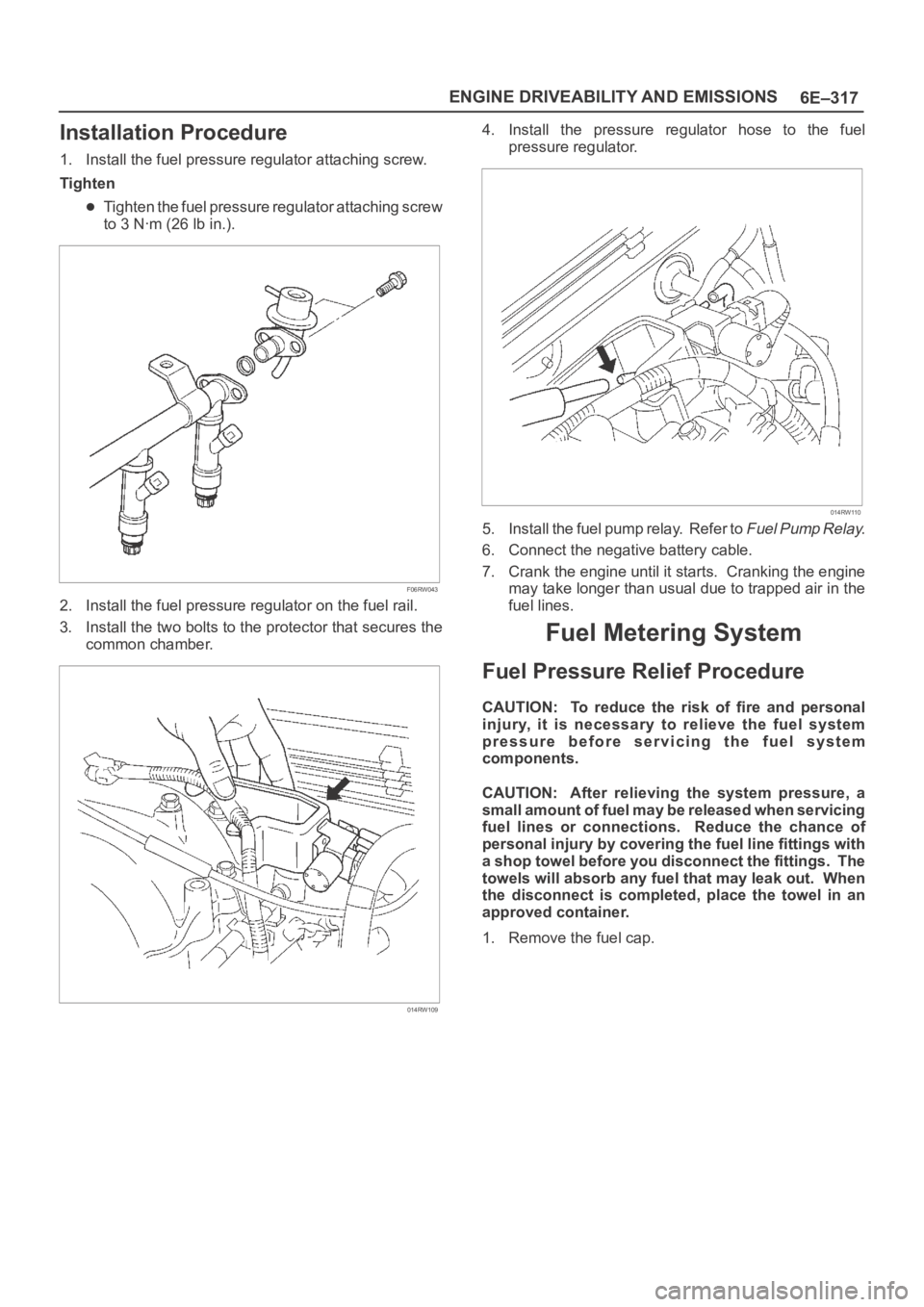
1. Install the fuel pressure regulator attaching screw.
Tighten
Tighten the fuel pressure regulator attaching screw
to 3 Nꞏm (26 lb in.).
F06RW043
2. Install the fuel pressure regulator on the fuel rail.
3. Install the two bolts to the protector that secures the
common chamber.
014RW109
4. Install the pressure regulator hose to the fuel
pressure regulator.
014RW110
5. Install the fuel pump relay. Refer to Fuel Pump Relay.
6. Connect the negative battery cable.
7. Crank the engine until it starts. Cranking the engine
may take longer than usual due to trapped air in the
fuel lines.
Fuel Metering System
Fuel Pressure Relief Procedure
CAUTION: To reduce the risk of fire and personal
injury, it is necessary to relieve the fuel system
pressure before servicing the fuel system
components.
CAUTION: After relieving the system pressure, a
small amount of fuel may be released when servicing
fuel lines or connections. Reduce the chance of
personal injury by covering the fuel line fittings with
a shop towel before you disconnect the fittings. The
towels will absorb any fuel that may leak out. When
the disconnect is completed, place the towel in an
approved container.
1. Remove the fuel cap.
Page 5349 of 6000
6A – 76 ENGINE MECHANICAL
3. Piston and Connecting Rod Assembly
1) Apply engine oil to the cylinder bores, the
connecting rod bearings and the crankshaft pins
and each piston ring and piston.
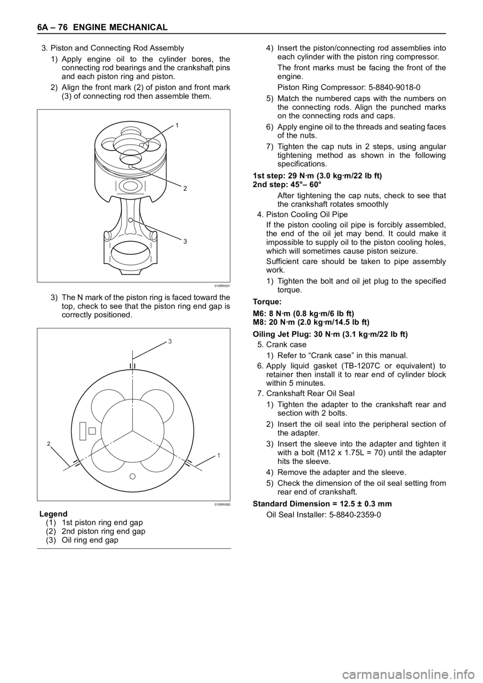
2) Align the front mark (2) of piston and front mark
(3) of connecting rod then assemble them.
3) The N mark of the piston ring is faced toward the
top, check to see that the piston ring end gap is
correctly positioned.
Legend
(1) 1st piston ring end gap
(2) 2nd piston ring end gap
(3) Oil ring end gap4) Insert the piston/connecting rod assemblies into
each cylinder with the piston ring compressor.
The front marks must be facing the front of the
engine.
Piston Ring Compressor: 5-8840-9018-0
5) Match the numbered caps with the numbers on
the connecting rods. Align the punched marks
on the connecting rods and caps.
6) Apply engine oil to the threads and seating faces
of the nuts.
7) Tighten the cap nuts in 2 steps, using angular
tightening method as shown in the following
specifications.
1st step: 29 Nꞏm (3.0 kgꞏm/22 lb ft)
2nd step: 45°– 60°
After tightening the cap nuts, check to see that
the crankshaft rotates smoothly
4. Piston Cooling Oil Pipe
If the piston cooling oil pipe is forcibly assembled,
the end of the oil jet may bend. It could make it
impossible to supply oil to the piston cooling holes,
which will sometimes cause piston seizure.
Sufficient care should be taken to pipe assembly
work.
1) Tighten the bolt and oil jet plug to the specified
torque.
To r q u e :
M6: 8 Nꞏm (0.8 kgꞏm/6 lb ft)
M8: 20 Nꞏm (2.0 kgꞏm/14.5 lb ft)
Oiling Jet Plug: 30 Nꞏm (3.1 kgꞏm/22 lb ft)
5. Crank case
1) Refer to “Crank case” in this manual.
6. Apply liquid gasket (TB-1207C or equivalent) to
retainer then install it to rear end of cylinder block
within 5 minutes.
7. Crankshaft Rear Oil Seal
1) Tighten the adapter to the crankshaft rear and
section with 2 bolts.
2) Insert the oil seal into the peripheral section of
the adapter.
3) Insert the sleeve into the adapter and tighten it
with a bolt (M12 x 1.75L = 70) until the adapter
hits the sleeve.
4) Remove the adapter and the sleeve.
5) Check the dimension of the oil seal setting from
rear end of crankshaft.
Standard Dimension = 12.5 ± 0.3 mm
Oil Seal Installer: 5-8840-2359-0
2
3
1
015RW051
3
1
2
015RW083
Page 5406 of 6000

ENGINE ELECTRICAL 6D – 3
ON-VEHICLE SERVICE
BATTERY CHARGING
Observe the following safety precautions when
charging the battery:
1. Never attempt to charge the battery when the fluid
level is below the lower level line on the side of the
battery. In this case, the battery must be replaced.
2. Pay close attention to the battery during the
charging procedure.
Battery charging should be discontinued or the rate
of charge reduced if the battery feels hot to the
touch.
Battery charging should be discontinued or the rate
of charge reduced if the battery begins to gas or
spew electrolyte from the vent holes.
3. In order to more easily view the hydrometer blue
dot or ring, it may be necessary to jiggle or tilt the
battery.
4. Battery temperature can have a great effect on
battery charging capacity.
5. The sealed battery used on this vehicle may be
either quick-charged or slow-charged in the same
manner as other batteries.
Whichever method you decide to use, be sure that
you completely charge the battery. Never partially
charge the battery.
JUMP STARTING
JUMP STARTING WITH AN AUXILIARY
(BOOSTER) BATTERY
CAUTION: Never push or tow the vehicle in an
attempt to start it. Serious damage to the emission
system as well as other vehicle parts will result.
Treat both the discharged battery and the booster
battery with great care when using jumper cables.
Carefully follow the jump starting procedure, being
careful at all times to avoid sparking.
WARNING: Failure to carefully follow the jump
starting procedure could result in the following:
1. Serious personal injury, particularly to your
eyes.
2. Property damage from a battery explosion,
battery acid, or an electrical fire.
3. Damage to the electronic components of one or
both vehicles.
Never expose the battery to an open flame or electrical
spark. Gas generated by the battery may catch fire or
explode. Remove any rings, watches, or other jewelry
before working around the battery. Protect your eyes by
wearing an approved set of goggles.
Never allow battery fluid to come in contact with your
eyes or skin.
Never allow battery fluid to come in contact with fabrics
or painted surfaces.
Battery fluid is a highly corrosive acid.Should battery fluid come in contact with your eyes,
skin, fabric, or a painted surface, immediately and
thoroughly rinse the affected area with clean tap water.
Never allow metal tools or jumper cables to come in
contact with the positive battery terminal, or any other
metal surface of the vehicle. This will protect against a
short circuit.
Always keep batteries out of the reach of young
children.
JUMP STARTING PROCEDURE
1. Set the vehicle parking brake.
If the vehicle is equipped with an automatic
transmission, place the selector lever in the “PARK”
position.
If the vehicle is equipped with a manual
transmission place the shift lever in the “NEUTRAL”
position.
Turn “OFF” the ignition.
Turn “OFF” all lights and any other accessory
requiring electrical power.
2. Look at the built-in hydrometer.
If the indication area of the built-in hydrometer is
completely clear, do not try to jump start.
3. Attach the end of one jumper cable to the positive
terminal of the booster battery.
Attach the other end of the same cable to the
positive terminal of the discharged battery.
Do not allow the vehicles to touch each other.
This will cause a ground connection, effectively
neutralizing the charging procedure.
Be sure that the booster battery has a 12 volt rating.
4. Attach one end of the remaining cable to the
negative terminal of the booster battery.
Attach the other end of the same cable to a solid
engine ground (such as the A/C compressor
bracket or the generator mounting bracket) of the
vehicle with the discharged battery.
This ground connection must be at least 450 mm
(18 in) from the battery of the vehicle whose battery
is being charged.
WARNING: Never attach the end of the jumper
cable directly to the negative terminal of the dead
battery.
5. Start the engine of the vehicle with the good battery.
Make sure that all unnecessary electrical
accessories have been turned “OFF”.
6. Start the engine of the vehicle with the dead battery.
7. To remove the jumper cables, follow the above
directions in the reverse order.
Be sure to first disconnect the negative cable from
the vehicle with the discharged battery.
Page 5643 of 6000
6E–214
4JX1–TC ENGINE DRIVEABILITY AND EMISSIONS
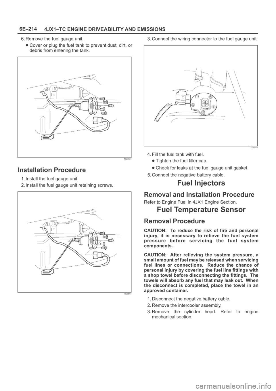
6. Remove the fuel gauge unit.
Cover or plug the fuel tank to prevent dust, dirt, or
debris from entering the tank.
TS22911
Installation Procedure
1. Install the fuel gauge unit.
2. Install the fuel gauge unit retaining screws.
TS22911
3. Connect the wiring connector to the fuel gauge unit.
TS23771
4. Fill the fuel tank with fuel.
Tighten the fuel filler cap.
Check for leaks at the fuel gauge unit gasket.
5. Connect the negative battery cable.
Fuel Injectors
Removal and Installation Procedure
Refer to Engine Fuel in 4JX1 Engine Section.
Fuel Temperature Sensor
Removal Procedure
CAUTION: To reduce the risk of fire and personal
injury, it is necessary to relieve the fuel system
pressure before servicing the fuel system
components.
CAUTION: After relieving the system pressure, a
small amount of fuel may be released when servicing
fuel lines or connections. Reduce the chance of
personal injury by covering the fuel line fittings with
a shop towel before disconnecting the fittings. The
towels will absorb any fuel that may leak out. When
the disconnect is completed, place the towel in an
approved container.
1. Disconnect the negative battery cable.
2. Remove the intercooler assembly.
3. Remove the cylinder head. Refer to engine
mechanical section.