1998 OPEL FRONTERA length
[x] Cancel search: lengthPage 4655 of 6000
6D3–24STARTING AND CHARGING SYSTEM
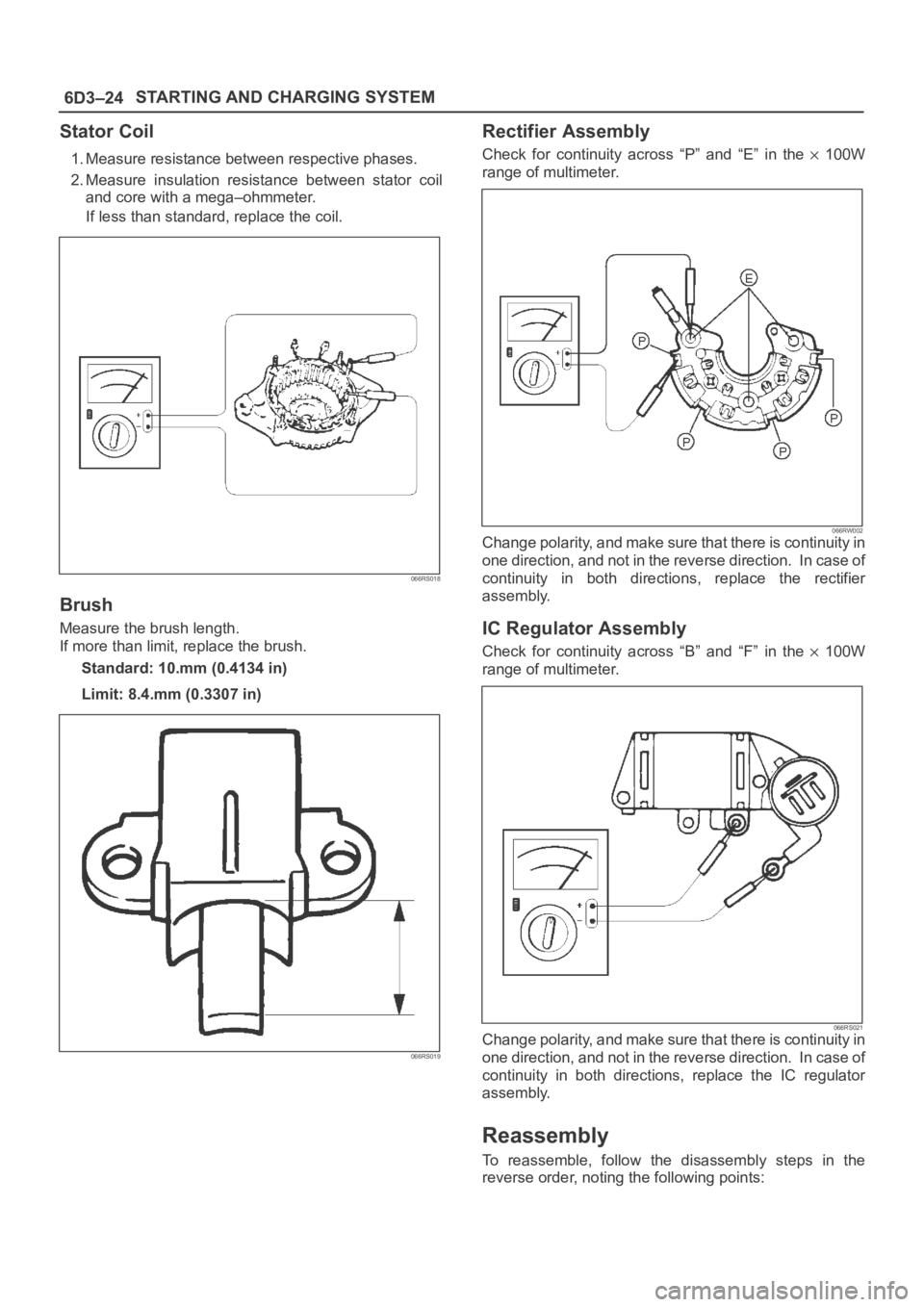
Stator Coil
1. Measure resistance between respective phases.
2. Measure insulation resistance between stator coil
and core with a mega–ohmmeter.
If less than standard, replace the coil.
066RS018
Brush
Measure the brush length.
If more than limit, replace the brush.
Standard: 10.mm (0.4134 in)
Limit: 8.4.mm (0.3307 in)
066RS019
Rectifier Assembly
Check for continuity across “P” and “E” in the 100W
range of multimeter.
066RW002Change polarity, and make sure that there is continuity in
one direction, and not in the reverse direction. In case of
continuity in both directions, replace the rectifier
assembly.
IC Regulator Assembly
Check for continuity across “B” and “F” in the 100W
range of multimeter.
066RS021Change polarity, and make sure that there is continuity in
one direction, and not in the reverse direction. In case of
continuity in both directions, replace the IC regulator
assembly.
Reassembly
To reassemble, follow the disassembly steps in the
reverse order, noting the following points:
Page 4695 of 6000
6E–38
ENGINE DRIVEABILITY AND EMISSIONS
General Service Information
OBD Serviceablity Issues
The list of non-vehicle faults that could affect the
performance of the OBD system has been compiled.
These non-vehicle faults vary from environmental
conditions to the quality of fuel used.
The illumination of the MIL (“Check Engine” lamp) due to
a non-vehicle fault could lead to misdiagnosis of the
vehicle, increased warranty expense and customer
dissatisfaction. The following list of non-vehicle faults
does not include every possible fault and may not apply
equally to all product lines.
Fuel Quality
Using fuel with the wrong octane rating for your vehicle
may cause driveability problems. Many of the major fuel
companies advertise that using “premium” gasoline will
improve the performance of your vehicle. Most premium
fuels use alcohol to increase the octane rating of the fuel.
Although alcohol-enhanced fuels may raise the octane
rating, the fuel’s ability to turn into vapor in cold
temperatures deteriorates. This may affect the starting
ability and cold driveability of the engine.
Low fuel levels can lead to fuel starvation, lean engine
operation, and eventually engine misfire.
Non-OEM Parts
All of the OBD diagnostics have been calibrated to run
with OEM parts. Something as simple as a
high-performance exhaust system that affects exhaust
system back pressure could potentially interfere with the
operation of the EGR valve and thereby turn on the MIL
(“Check Engine” lamp). Small leaks in the exhaust
system near the post catalyst oxygen sensor can also
cause the MIL (“Check Engine” lamp) to turn on.
Aftermarket electronics, such as cellular phones,
stereos, and anti-theft devices, may radiate EMI into the
control system if they are improperly installed. This may
cause a false sensor reading and turn on the MIL (“Check
Engine” lamp).
Environment
Temporary environmental conditions, such as localized
flooding, will have an effect on the vehicle ignition system.
If the ignition system is rain-soaked, it can temporarily
cause engine misfire and turn on the MIL (“Check Engine”
lamp).
Poor Vehicle Maintenance
The sensitivity of OBD diagnostics will cause the MIL
(“Check Engine” lamp) to turn on if the vehicle is not
maintained properly. Restricted air filters, fuel filters, and
crankcase deposits due to lack of oil changes or improper
oil viscosity can trigger actual vehicle faults that were not
previously monitored prior to OBD. Poor vehicle
maintenance can not be classified as a “non-vehicle
fault”, but with the sensitivity of OBD diagnostics, vehicle
maintenance schedules must be more closely followed.Related System Faults
Many of the OBD system diagnostics will not run if the
PCM detects a fault on a related system or component.
One example would be that if the PCM detected a Misfire
fault, the diagnostics on the catalytic converter would be
suspended until Misfire fault was repaired. If the Misfire
fault was severe enough, the catalytic converter could be
damaged due to overheating and would never set a
Catalyst DTC until the Misfire fault was repaired and the
Catalyst diagnostic was allowed to run to completion. If
this happens, the customer may have to make two trips to
the dealership in order to repair the vehicle.
Maintenance Schedule
Refer to the Maintenance Schedule.
Visual / Physical Engine Compartment
Inspection
Perform a careful visual and physical engine
compartment inspection when performing any diagnostic
procedure or diagnosing the cause of an emission test
failure. This can often lead to repairing a problem without
further steps. Use the following guidelines when
performing a visual/physical inspection:
Inspect all vacuum hoses for punches, cuts,
disconnects, and correct routing.
Inspect hoses that are difficult to see behind other
components.
Inspect all wires in the engine compartment for proper
connections, burned or chafed spots, pinched wires,
contact with sharp edges or contact with hot exhaust
manifolds or pipes.
Basic Knowledge of Tools Required
NOTE: Lack of basic knowledge of this powertrain when
performing diagnostic procedures could result in an
incorrect diagnosis or damage to powertrain
components. Do not attempt to diagnose a powertrain
problem without this basic knowledge.
A basic understanding of hand tools is necessary to effec-
tively use this section of the Service Manual.
Serial Data Communications
Class II Serial Data Communications
This vehicle utilizes the “Class II” communication system.
Each bit of information can have one of two lengths: long
or short. This allows vehicle wiring to be reduced by
transmitting and receiving multiple signals over a single
wire. The messages carried on Class II data streams are
also prioritized. If two messages attempt to establish
communications on the data line at the same time, only
the message with higher priority will continue. The device
with the lower priority message must wait. The most
significant result of this regulation is that it provides Tech 2
manufacturers with the capability to access data from any
make or model vehicle that is sold.
Page 4748 of 6000
6E–91 ENGINE DRIVEABILITY AND EMISSIONS
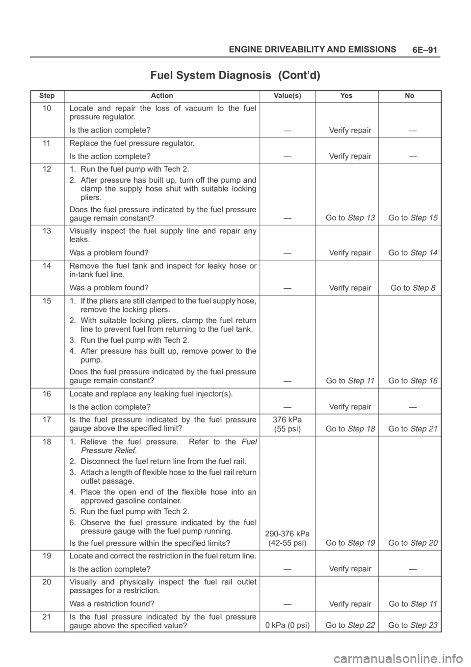
Fuel System Diagnosis
StepNo Ye s Va l u e ( s ) Action
10Locate and repair the loss of vacuum to the fuel
pressure regulator.
Is the action complete?
—Verify repair—
11Replace the fuel pressure regulator.
Is the action complete?
—Verify repair—
121. Run the fuel pump with Tech 2.
2. After pressure has built up, turn off the pump and
clamp the supply hose shut with suitable locking
pliers.
Does the fuel pressure indicated by the fuel pressure
gauge remain constant?
—Go to Step 13Go to Step 15
13Visually inspect the fuel supply line and repair any
leaks.
Was a problem found?
—Verify repairGo to Step 14
14Remove the fuel tank and inspect for leaky hose or
in-tank fuel line.
Was a problem found?
—Verify repairGo to Step 8
151. If the pliers are still clamped to the fuel supply hose,
remove the locking pliers.
2. With suitable locking pliers, clamp the fuel return
line to prevent fuel from returning to the fuel tank.
3. Run the fuel pump with Tech 2.
4. After pressure has built up, remove power to the
pump.
Does the fuel pressure indicated by the fuel pressure
gauge remain constant?
—Go to Step 11Go to Step 16
16Locate and replace any leaking fuel injector(s).
Is the action complete?
—Verify repair—
17Is the fuel pressure indicated by the fuel pressure
gauge above the specified limit?376 kPa
(55 psi)
Go to Step 18Go to Step 21
181. Relieve the fuel pressure. Refer to the Fuel
Pressure Relief.
2. Disconnect the fuel return line from the fuel rail.
3. Attach a length of flexible hose to the fuel rail return
outlet passage.
4. Place the open end of the flexible hose into an
approved gasoline container.
5. Run the fuel pump with Tech 2.
6. Observe the fuel pressure indicated by the fuel
pressure gauge with the fuel pump running.
Is the fuel pressure within the specified limits?
290-376 kPa
(42-55 psi)
Go to Step 19Go to Step 20
19Locate and correct the restriction in the fuel return line.
Is the action complete?
—Verify repair—
20Visually and physically inspect the fuel rail outlet
passages for a restriction.
Was a restriction found?
—Verify repairGo to Step 11
21Is the fuel pressure indicated by the fuel pressure
gauge above the specified value?
0kPa (0psi)Go to Step 22Go to Step 23
Page 5414 of 6000
ENGINE ELECTRICAL 6D – 11
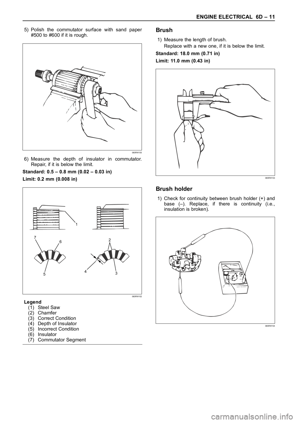
5) Polish the commutator surface with sand paper
#500 to #600 if it is rough.
6) Measure the depth of insulator in commutator.
Repair, if it is below the limit.
Standard: 0.5 – 0.8 mm (0.02 – 0.03 in)
Limit: 0.2 mm (0.008 in)
Legend
(1) Steel Saw
(2) Chamfer
(3) Correct Condition
(4) Depth of Insulator
(5) Incorrect Condition
(6) Insulator
(7) Commutator SegmentBrush
1) Measure the length of brush.
Replace with a new one, if it is below the limit.
Standard: 18.0 mm (0.71 in)
Limit: 11.0 mm (0.43 in)
Brush holder
1) Check for continuity between brush holder (+) and
base (–). Replace, if there is continuity (i.e.,
insulation is broken).
065RW105
1
6
53 42 7
065RW102
065RW103
065RW104
Page 5423 of 6000
6D – 20 ENGINE ELECTRICAL
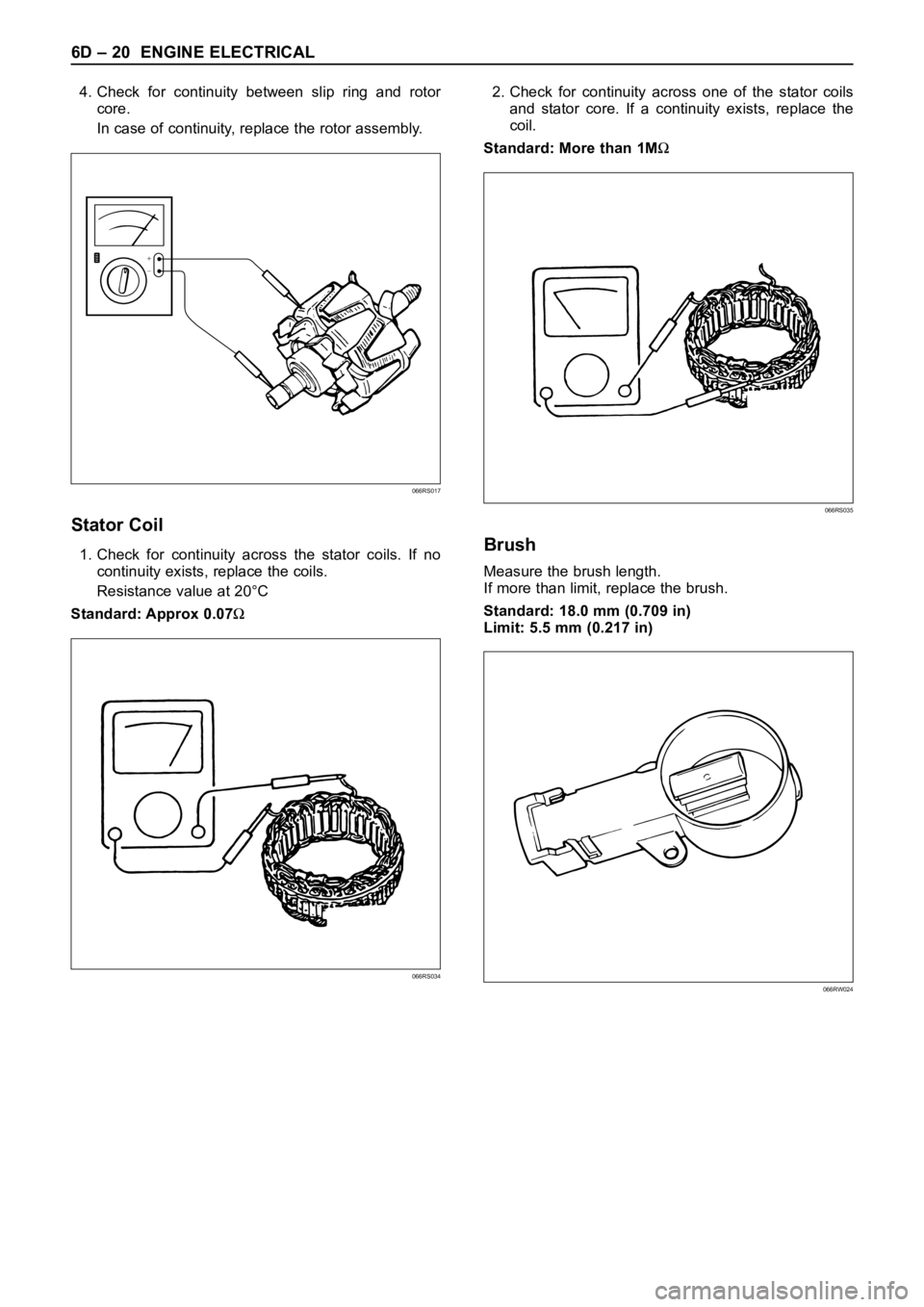
4. Check for continuity between slip ring and rotor
core.
In case of continuity, replace the rotor assembly.
Stator Coil
1. Check for continuity across the stator coils. If no
continuity exists, replace the coils.
Resistance value at 20°C
Standard: Approx 0.07
2. Check for continuity across one of the stator coils
and stator core. If a continuity exists, replace the
coil.
Standard: More than 1M
Brush
Measure the brush length.
If more than limit, replace the brush.
Standard: 18.0 mm (0.709 in)
Limit: 5.5 mm (0.217 in)
+
−
066RS017
066RS035
066RW024066RS034
Page 5454 of 6000
6E–25 4JX1–TC ENGINE DRIVEABILITY AND EMISSIONS
General Service Information
Serviceability Issues
Non-OEM Parts
All of the OBD diagnostics have been calibrated to run
with OEM parts. Accordingly, if commercially sold sensor
or switch is installed, it makes a wrong diagnosis and turn
on the MIL (“Check Engine” lamp).
Aftermarket electronics, such as cellular phones,
stereos, and anti-theft devices, may radiate EMI into the
control system if they are improperly installed. This may
cause a false sensor reading and turn on the MIL (“Check
Engine” lamp).
Poor Vehicle Maintenance
The sensitivity of OBD diagnostics will cause the MIL
(“Check Engine” lamp) to turn on if the vehicle is not
maintained properly. Restricted oil filters, fuel filters, and
crankcase deposits due to lack of oil changes or improper
oil viscosity can trigger actual vehicle faults that were not
previously monitored prior to OBD. Poor vehicle
maintenance can not be classified as a “non-vehicle
fault”, but with the sensitivity of OBD diagnostics, vehicle
maintenance schedules must be more closely followed.
Related System Faults
Many of the OBD system diagnostics will not run if the
ECM detects a fault on a related system or component.
Visual/Physical Engine Compartment
Inspection
Perform a careful visual and physical engine
compartment inspection when performing any diagnostic
procedure or diagnosing the cause of an emission test
failure. This can often lead to repairing a problem without
further steps. Use the following guidelines when
performing a visual/physical inspection:
Inspect all vacuum hoses for punches, cuts,
disconnects, and correct routing.
Inspect hoses that are difficult to see behind other
components.
Inspect all wires in the engine compartment for proper
connections, burned or chafed spots, pinched wires,
contact with sharp edges or contact with hot exhaust
manifolds or pipes.
Basic Knowledge of Tools Required
NOTE: Lack of basic knowledge of this powertrain when
performing diagnostic procedures could result in an
incorrect diagnosis or damage to powertrain
components. Do not attempt to diagnose a powertrain
problem without this basic knowledge.
A basic understanding of hand tools is necessary to effec-
tively use this section of the Service Manual.
Serial Data Communications
Class II Serial Data Communications
This vehicle utilizes the “Class II” communication system.
Each bit of information can have one of two lengths: longor short. This allows vehicle wiring to be reduced by
transmitting and receiving multiple signals over a single
wire. The messages carried on Class II data streams are
also prioritized. If two messages attempt to establish
communications on the data line at the same time, only
the message with higher priority will continue. The device
with the lower priority message must wait.
On this vehicle the Tech 2 displays the actual values for
vehicle parameters. It will not be necessary to perform
any conversions from coded values to actual values.
On-Board Diagnostic (OBD)
On-Board Diagnostic Tests
A diagnostic test is a series of steps, the result of which is
a pass or fail reported to the diagnostic executive. When
a diagnostic test reports a pass result, the diagnostic
executive records the following data:
The diagnostic test has been completed since the last
ignition cycle.
The diagnostic test has passed during the current
ignition cycle.
The fault identified by the diagnostic test is not
currently active.
When a diagnostic test reports a fail result, the diagnostic
executive records the following data:
The diagnostic test has been completed since the last
ignition cycle.
The fault identified by the diagnostic test is currently
active.
The fault has been active during this ignition cycle.
The operating conditions at the time of the failure.
Comprehensive Component Monitor
Diagnostic Operation
Comprehensive component monitoring diagnostics are
required to operate engine properly.
Input Components:
Input components are monitored for circuit continuity and
out-of-range values. This includes rationality checking.
Rationality checking refers to indicating a fault when the
signal from a sensor does not seem reasonable. Accel
Position (AP) sensor that indicates high throttle position
at low engine loads or MAP voltage. Input components
may include, but are not limited to the following sensors:
Intake Air Temperature (IAT) Sensor
Crankshaft Position (CKP) Sensor
Intake throttle Position (ITP) Sensor
Engine Coolant Temperature (ECT) Sensor
Camshaft Position (CMP) Sensor
Manifold absolute Pressure (MAP) Sensor
Accel Position Sensor
Fuel Temp Sensor
Rail Pressure Sensor
Oil Temp Sensor
EGR Pressure Sensor
Vehicle Speed Sensor
Page 5866 of 6000
AUTOMATIC TRANSMISSION (AW30-40LE) 7A–85
244RY00018
244RY00017
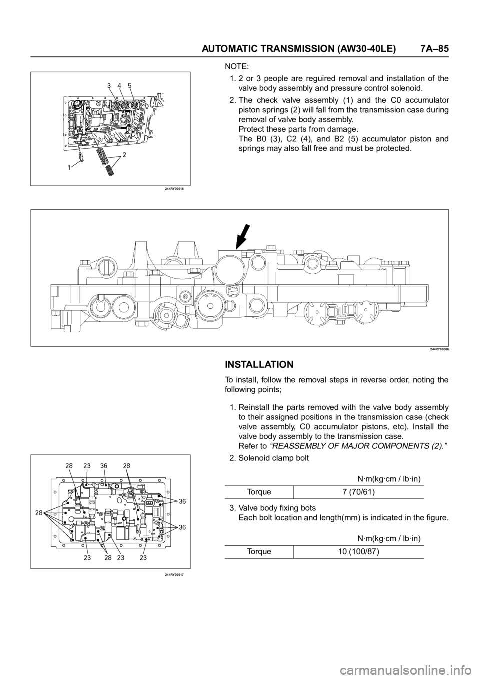
NOTE:
1. 2 or 3 people are reguired removal and installation of the
valve body assembly and pressure control solenoid.
2. The check valve assembly (1) and the C0 accumulator
piston springs (2) will fall from the transmission case during
removal of valve body assembly.
Protect these parts from damage.
The B0 (3), C2 (4), and B2 (5) accumulator piston and
springs may also fall free and must be protected.
244RY00006
INSTALLATION
To install, follow the removal steps in reverse order, noting the
following points;
1. Reinstall the par ts removed with the valve body assembly
to their assigned positions in the transmission case (check
valve assembly, C0 accumulator pistons, etc). Install the
valve body assembly to the transmission case.
Refer to
“REASSEMBLY OF MAJOR COMPONENTS (2).”
2. Solenoid clamp bolt
3. Valve body fixing bots
Each bolt location and length(mm) is indicated in the figure.Nꞏm(kgꞏcm / lbꞏin)
Torque 7 (70/61)
Nꞏm(kgꞏcm / lbꞏin)
Torque 10 (100/87)
Page 5882 of 6000
AUTOMATIC TRANSMISSION (AW30-40LE) 7A–101
252RY00005
252RY00006
248RY00004
248RY00005
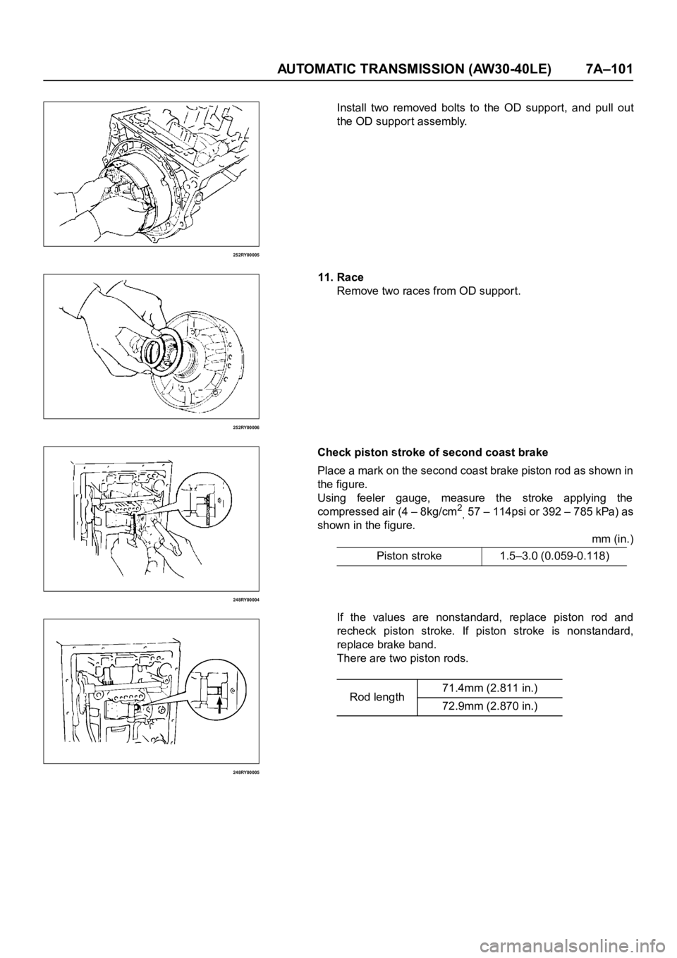
Install two removed bolts to the OD support, and pull out
the OD suppor t assembly.
11. Race
Remove two races from OD suppor t.
Check piston stroke of second coast brake
Place a mark on the second coast brake piston rod as shown in
the figure.
Using feeler gauge, measure the stroke applying the
compressed air (4 – 8kg/cm
2
, 57 – 114psi or 392 – 785 kPa) as
shown in the figure.
mm (in.)
If the values are nonstandard, replace piston rod and
recheck piston stroke. If piston stroke is nonstandard,
replace brake band.
There are two piston rods.Piston stroke 1.5–3.0 (0.059-0.118)
Rod length71.4mm (2.811 in.)
72.9mm (2.870 in.)