Page 4261 of 6000
4C–55 DRIVE SHAFT SYSTEM
Main Data and Specifications
General Specifications
Engine6VE1 (3.5L)6VD1 (3.2L)4JX1 (3.0L)4JG2 (3.1L)
Transmission
M/TA/T
A/T
with
TOD
M/TA/T
A/T
with
TOD
M/TA/TM/TA/T
ConstructionHollow steel tube with yoke and spider type universal joint
LengthS
W
B
668mm (26.30in)—846mm
(33.31in)678mm
(26.69in)—604mm (23.78in)810mm
(31.89in)—
L
W
B
1093mm (43.03in)1075mm
(42.32in)1271mm
(50.04in)1103mm
(43.43in)1083mm
(42.64in)1029mm (40.51in)1236mm
(48.66in)1037mm
(40.83in)
Outside
diamterS
W
B
68.9mm (2.71in)—68.9mm (2.71in)—68.9mm (2.71in)—
LW
B68.9mm (2.71in)82.6mm
(3.25in)68.9mm (2.71in)82.6mm
(3.25in)68.9mm
(2.71in)
Torque Specifications
E04RW023
Page 4296 of 6000
TRANSFER CASE (STANDARD TYPE)
4D1–35
Limit : 3.0 mm (0.118 in)
226RS037
2WD–4WD 3–Cone Synchronizer (Shift On
The Fly model)
1. Use a thickness gauge to measure the clearance
between the block ring and the dog teeth.
2. If the measured value exceeds the specified limit, the
2WD–4WD synchronizer assembly must be
replaced.
Block ring and insert clearance
Standard : 1.5 mm (0.059 in)
Limit : 0.8 mm (0.031 in)
226RW142
Clutch Hub and Insert Clearance
1. Use a thickness gauge to measure the clearance
between the clutch hub and the insert.
2. If the measured value exceeds the specified limit, the
clutch hub and the insert must be replaced.
Clutch hub and insert clearance
Standard : 0.01–0.19 mm (0.0004–0.0075 in)
Limit : 0.3 mm (0.012 in)
226RS038
Detent Springs
1. Inspect the springs for distortion, cracks or wear.
Replace if these conditions are present.
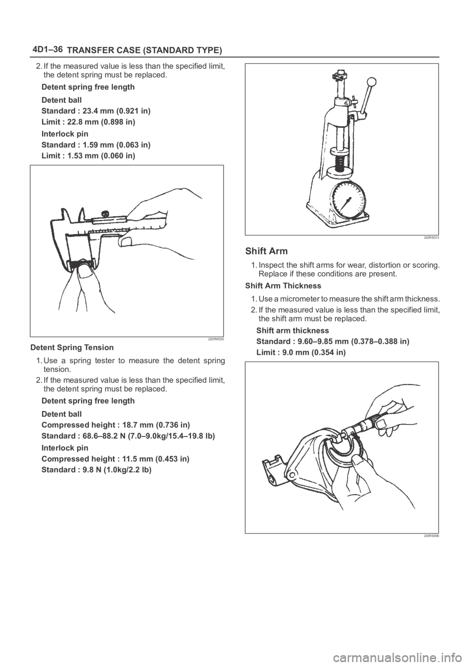
Detent Spring Free Length
1. Use a vernier caliper to measure the detent spring
free length.
Page 4297 of 6000
4D1–36
TRANSFER CASE (STANDARD TYPE)
2. If the measured value is less than the specified limit,
the detent spring must be replaced.
Detent spring free length
Detent ball
Standard : 23.4 mm (0.921 in)
Limit : 22.8 mm (0.898 in)
Interlock pin
Standard : 1.59 mm (0.063 in)
Limit : 1.53 mm (0.060 in)
220RW035
Detent Spring Tension
1. Use a spring tester to measure the detent spring
tension.
2. If the measured value is less than the specified limit,
the detent spring must be replaced.
Detent spring free length
Detent ball
Compressed height : 18.7 mm (0.736 in)
Standard : 68.6–88.2 N (7.0–9.0kg/15.4–19.8 lb)
Interlock pin
Compressed height : 11.5 mm (0.453 in)
Standard : 9.8 N (1.0kg/2.2 lb)
220RS013
Shift Arm
1. Inspect the shift arms for wear, distortion or scoring.
Replace if these conditions are present.
Shift Arm Thickness
1. Use a micrometer to measure the shift arm thickness.
2. If the measured value is less than the specified limit,
the shift arm must be replaced.
Shift arm thickness
Standard : 9.60–9.85 mm (0.378–0.388 in)
Limit : 9.0 mm (0.354 in)
230RS006
Page 4299 of 6000
4D1–38
TRANSFER CASE (STANDARD TYPE)
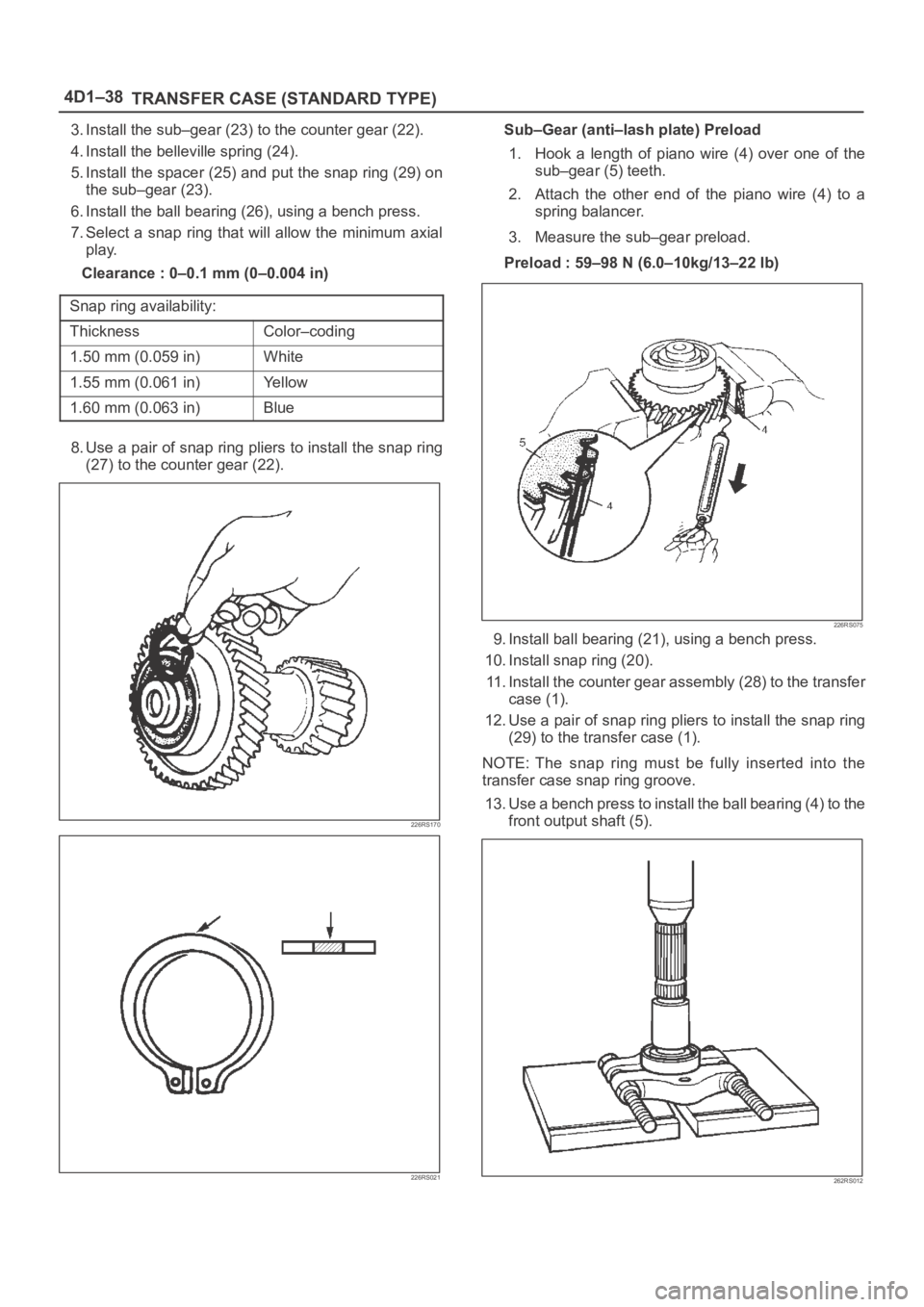
3. Install the sub–gear (23) to the counter gear (22).
4. Install the belleville spring (24).
5. Install the spacer (25) and put the snap ring (29) on
the sub–gear (23).
6. Install the ball bearing (26), using a bench press.
7. Select a snap ring that will allow the minimum axial
play.
Clearance : 0–0.1 mm (0–0.004 in)
Snap ring availability:
ThicknessColor–coding
1.50 mm (0.059 in)White
1.55 mm (0.061 in)Yellow
1.60 mm (0.063 in)Blue
8. Use a pair of snap ring pliers to install the snap ring
(27) to the counter gear (22).
226RS170
226RS021
Sub–Gear (anti–lash plate) Preload
1. Hook a length of piano wire (4) over one of the
sub–gear (5) teeth.
2. Attach the other end of the piano wire (4) to a
spring balancer.
3. Measure the sub–gear preload.
Preload : 59–98 N (6.0–10kg/13–22 lb)
226RS075
9. Install ball bearing (21), using a bench press.
10. Install snap ring (20).
11. Install the counter gear assembly (28) to the transfer
case (1).
12. Use a pair of snap ring pliers to install the snap ring
(29) to the transfer case (1).
NOTE: The snap ring must be fully inserted into the
transfer case snap ring groove.
13. Use a bench press to install the ball bearing (4) to the
front output shaft (5).
262RS012
Page 4302 of 6000
TRANSFER CASE (STANDARD TYPE)
4D1–41
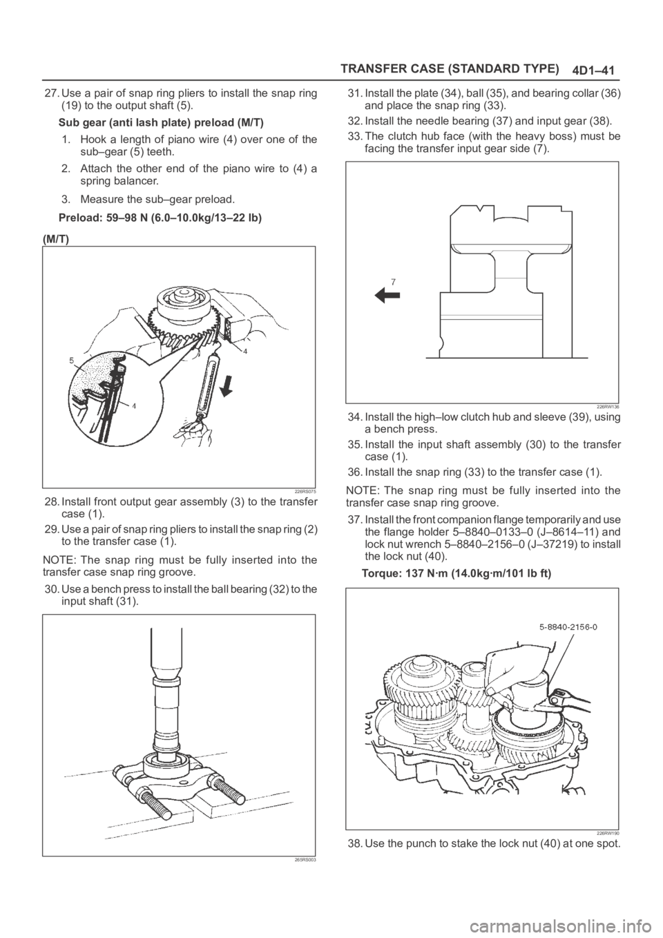
27. Use a pair of snap ring pliers to install the snap ring
(19) to the output shaft (5).
Sub gear (anti lash plate) preload (M/T)
1. Hook a length of piano wire (4) over one of the
sub–gear (5) teeth.
2. Attach the other end of the piano wire to (4) a
spring balancer.
3. Measure the sub–gear preload.
Preload: 59–98 N (6.0–10.0kg/13–22 lb)
(M/T)
226RS075
28. Install front output gear assembly (3) to the transfer
case (1).
29. Use a pair of snap ring pliers to install the snap ring (2)
to the transfer case (1).
NOTE: The snap ring must be fully inserted into the
transfer case snap ring groove.
30. Use a bench press to install the ball bearing (32) to the
input shaft (31).
265RS003
31. Install the plate (34), ball (35), and bearing collar (36)
and place the snap ring (33).
32. Install the needle bearing (37) and input gear (38).
33. The clutch hub face (with the heavy boss) must be
facing the transfer input gear side (7).
226RW136
34. Install the high–low clutch hub and sleeve (39), using
a bench press.
35. Install the input shaft assembly (30) to the transfer
case (1).
36. Install the snap ring (33) to the transfer case (1).
NOTE: The snap ring must be fully inserted into the
transfer case snap ring groove.
37. Install the front companion flange temporarily and use
the flange holder 5–8840–0133–0 (J–8614–11) and
lock nut wrench 5–8840–2156–0 (J–37219) to install
the lock nut (40).
Torque: 137 Nꞏm (14.0kgꞏm/101 lb ft)
226RW190
38. Use the punch to stake the lock nut (40) at one spot.
Page 4334 of 6000
4D2–27 TRANSFER CASE (TOD)
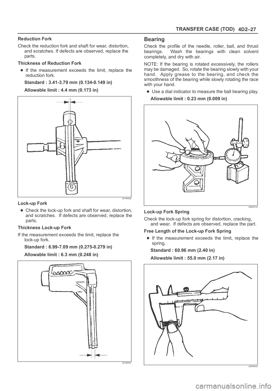
Reduction Fork
Check the reduction fork and shaft for wear, distortion,
and scratches. If defects are observed, replace the
parts.
Thickness of Reduction Fork
If the measurement exceeds the limit, replace the
reduction fork.
Standard : 3.41-3.79 mm (0.134-0.149 in)
Allowable limit : 4.4 mm (0.173 in)
261RW026
Lock-up Fork
Check the lock-up fork and shaft for wear, distortion,
and scratches. If defects are observed, replace the
parts.
Thickness Lock-up Fork
If the measurement exceeds the limit, replace the
lock-up fork.
Standard : 6.99-7.09 mm (0.275-0.279 in)
Allowable limit : 6.3 mm (0.248 in)
261RW027
Bearing
Check the profile of the needle, roller, ball, and thrust
bearings. Wash the bearings with clean solvent
completely, and dry with air.
NOTE: If the bearing is rotated excessively, the rollers
may be damaged. So, rotate the bearing slowly with your
hand. Apply grease to the bearing, and check the
smoothness of the bearing while slowly rotating the race
with your hand.
Use a dial indicator to measure the ball bearing play.
Allowable limit : 0.23 mm (0.009 in)
226RW143
Lock-up Fork Spring
Check the lock-up fork spring for distortion, cracking,
and wear. If defects are observed, replace the part.
Free Length of the Lock-up Fork Spring
If the measurement exceeds the limit, replace the
spring.
Standard : 60.96 mm (2.40 in)
Allowable limit : 55.0 mm (2.17 in)
220RW045
Page 4335 of 6000
4D2–28
TRANSFER CASE (TOD)
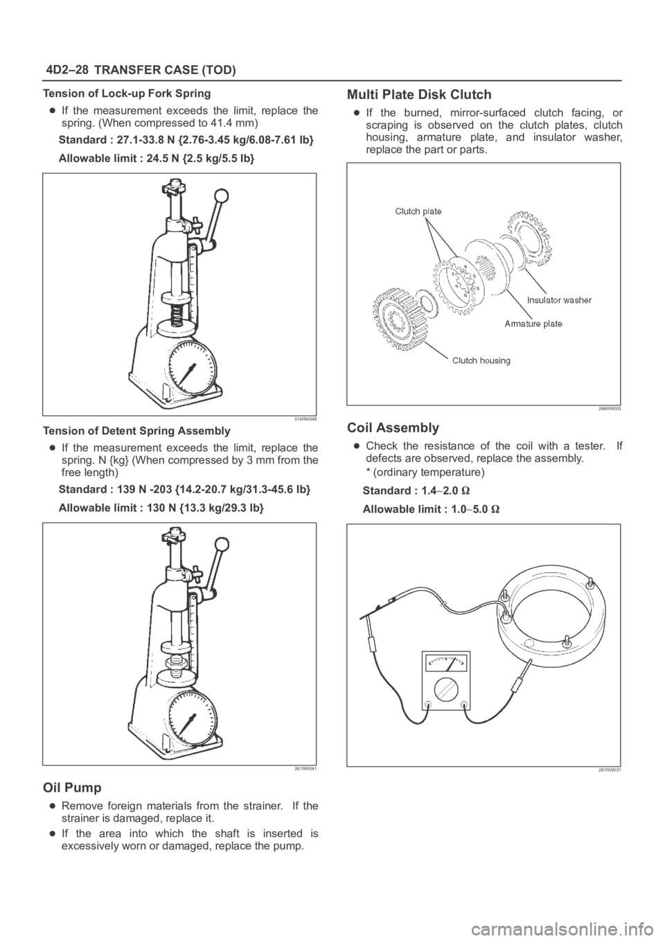
Tension of Lock-up Fork Spring
If the measurement exceeds the limit, replace the
spring. (When compressed to 41.4 mm)
Standard : 27.1-33.8 N {2.76-3.45 kg/6.08-7.61 Ib}
Allowable limit : 24.5 N {2.5 kg/5.5 Ib}
014RW048
Tension of Detent Spring Assembly
If the measurement exceeds the limit, replace the
spring. N {kg} (When compressed by 3 mm from the
free length)
Standard : 139 N -203 {14.2-20.7 kg/31.3-45.6 Ib}
Allowable limit : 130 N {13.3 kg/29.3 Ib}
261RW041
Oil Pump
Remove foreign materials from the strainer. If the
strainer is damaged, replace it.
If the area into which the shaft is inserted is
excessively worn or damaged, replace the pump.
Multi Plate Disk Clutch
If the burned, mirror-surfaced clutch facing, or
scraping is observed on the clutch plates, clutch
housing, armature plate, and insulator washer,
replace the part or parts.
266RW003
Coil Assembly
Check the resistance of the coil with a tester. If
defects are observed, replace the assembly.
* (ordinary temperature)
Standard : 1.4
2.0
Allowable limit : 1.05.0
261RW031
Page 4642 of 6000
6D3–11 STARTING AND CHARGING SYSTEM
Brush
Measure the length of brush.
Replace with a new one, if it is below the limit.
Standard: 16 mm (0.63 in)
Limit: 11 mm (0.43 in)
065RW014
Brush Holder
Check for continuity between brush holder (+) (4) and
base (–). Replace, if there is continuity (i.e., insulation is
broken).
065RW015
Magnetic Switch
Check for continuity of shunt coil between terminals S and
M.
Replace, if there is no continuity (i.e., coil is
disconnected).
065RW016
Continuity of Series Coil
Check for continuity between terminals S and M.
Replace, if there is no continuity (i.e., coil is
disconnected).
065RW017