1998 OPEL FRONTERA sensor
[x] Cancel search: sensorPage 2072 of 6000
6E–179 4JX1–TC ENGINE DRIVEABILITY AND EMISSIONS
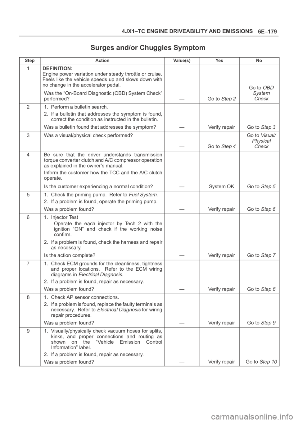
Surges and/or Chuggles Symptom
StepActionVa l u e ( s )Ye sNo
1DEFINITION:
Engine power variation under steady throttle or cruise.
Feels like the vehicle speeds up and slows down with
no change in the accelerator pedal.
Was the “On-Board Diagnostic (OBD) System Check”
performed?
—Go to Step 2
Go to OBD
System
Check
21. Perform a bulletin search.
2. If a bulletin that addresses the symptom is found,
correct the condition as instructed in the bulletin.
Was a bulletin found that addresses the symptom?
—Verify repairGo to Step 3
3Was a visual/physical check performed?
—Go to Step 4
Go to Visual/
Physical
Check
4Be sure that the driver understands transmission
torque converter clutch and A/C compressor operation
as explained in the owner’s manual.
Inform the customer how the TCC and the A/C clutch
operate.
Is the customer experiencing a normal condition?
—System OKGo to Step 5
51. Check the priming pump. Refer to Fuel System.
2. If a problem is found, operate the priming pump.
Was a problem found?
—Verify repairGo to Step 6
61. Injector Test
Operate the each injector by Tech 2 with the
ignition “ON” and check if the working noise
confirm.
2. If a problem is found, check the harness and repair
as necessary.
Is the action complete?
—Verify repairGo to Step 7
71. Check ECM grounds for the cleanliness, tightness
and proper locations. Refer to the ECM wiring
diagrams in
Electrical Diagnosis.
2. If a problem is found, repair as necessary.
Was a problem found?
—Verify repairGo to Step 8
81. Check AP sensor connections.
2. If a problem is found, replace the faulty terminals as
necessary. Refer to
Electrical Diagnosis for wiring
repair procedures.
Was a problem found?
—Verify repairGo to Step 9
91. Visually/physically check vacuum hoses for splits,
kinks, and proper connections and routing as
shown on the “Vehicle Emission Control
Information” label.
2. If a problem is found, repair as necessary.
Was a problem found?
—Verify repairGo to Step 10
Page 2074 of 6000
6E–181 4JX1–TC ENGINE DRIVEABILITY AND EMISSIONS
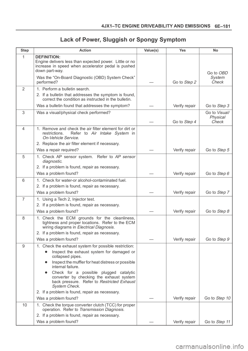
Lack of Power, Sluggish or Spongy Symptom
StepActionVa l u e ( s )Ye sNo
1DEFINITION:
Engine delivers less than expected power. Little or no
increase in speed when accelerator pedal is pushed
down part-way.
Was the “On-Board Diagnostic (OBD) System Check”
performed?
—Go to Step 2
Go to OBD
System
Check
21. Perform a bulletin search.
2. If a bulletin that addresses the symptom is found,
correct the condition as instructed in the bulletin.
Was a bulletin found that addresses the symptom?
—Verify repairGo to Step 3
3Was a visual/physical check performed?
—Go to Step 4
Go to Visual/
Physical
Check
41. Remove and check the air filter element for dirt or
restrictions. Refer to
Air Intake System in
On-Vehicle Service.
2. Replace the air filter element if necessary.
Was a repair required?
—Verify repairGo to Step 5
51. Check AP sensor system. Refer to AP sensor
diagnostic
.
2. If a problem is found, repair as necessary.
Was a problem found?
—Verify repairGo to Step 6
61. Check for water-or alcohol-contaminated fuel.
2. If a problem is found, repair as necessary.
Was a problem found?
—Verify repairGo to Step 7
71. Using a Tech 2, Injector test.
2. If a problem is found, repair as necessary.
Was a problem found?
—Verify repairGo to Step 8
81. Check the ECM grounds for the cleanliness,
tightness and proper locations. Refer to the ECM
wiring diagrams in
Electrical Diagnosis.
2. If a problem is found, repair as necessary.
Was a problem found?
—Verify repairGo to Step 9
91. Check the exhaust system for possible restriction:
Inspect the exhaust system for damaged or
collapsed pipes.
Inspect the muffler for heat distress or possible
internal failure.
Check for a possible plugged catalytic
converter by checking the exhaust system
back pressure. Refer to
Restricted Exhaust
System Check
.
2. If a problem is found, repair as necessary.
Was a problem found?
—Verify repairGo to Step 10
101. Check the torque converter clutch (TCC) for proper
operation. Refer to
Transmission Diagnosis.
2. If a problem is found, repair as necessary.
Was a problem found?
—Verify repairGo to Step 11
Page 2079 of 6000
6E–186
4JX1–TC ENGINE DRIVEABILITY AND EMISSIONS
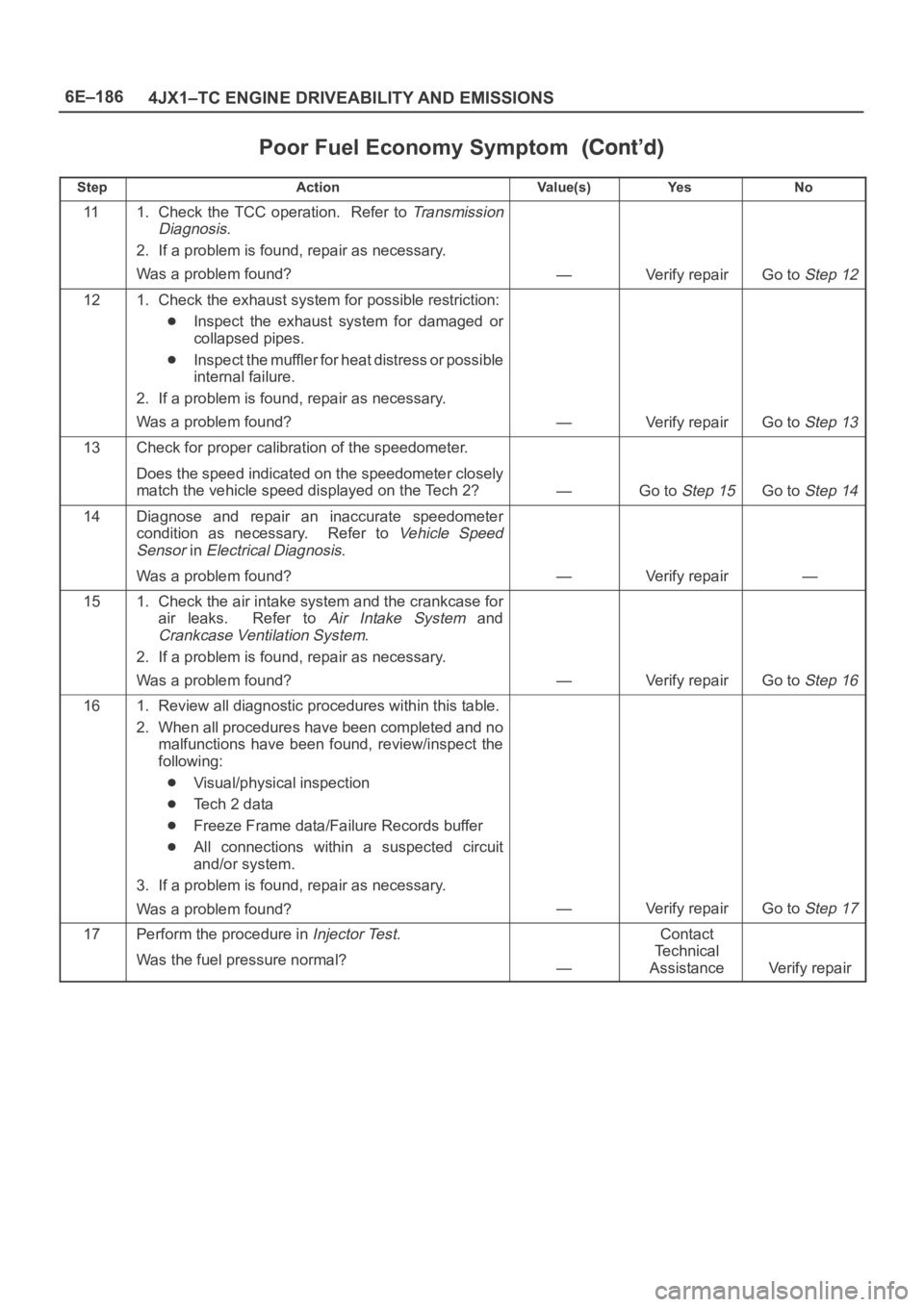
Poor Fuel Economy Symptom
StepNo Ye s Va l u e ( s ) Action
111. Check the TCC operation. Refer to Transmission
Diagnosis
.
2. If a problem is found, repair as necessary.
Was a problem found?
—Verify repairGo to Step 12
121. Check the exhaust system for possible restriction:
Inspect the exhaust system for damaged or
collapsed pipes.
Inspect the muffler for heat distress or possible
internal failure.
2. If a problem is found, repair as necessary.
Was a problem found?
—Verify repairGo to Step 13
13Check for proper calibration of the speedometer.
Does the speed indicated on the speedometer closely
match the vehicle speed displayed on the Tech 2?
—Go to Step 15Go to Step 14
14Diagnose and repair an inaccurate speedometer
condition as necessary. Refer to
Vehicle Speed
Sensor
in Electrical Diagnosis.
Was a problem found?
—Verify repair—
151. Check the air intake system and the crankcase for
air leaks. Refer to
Air Intake System and
Crankcase Ventilation System.
2. If a problem is found, repair as necessary.
Was a problem found?
—Verify repairGo to Step 16
161. Review all diagnostic procedures within this table.
2. When all procedures have been completed and no
malfunctions have been found, review/inspect the
following:
Visual/physical inspection
Te c h 2 d a t a
Freeze Frame data/Failure Records buffer
All connections within a suspected circuit
and/or system.
3. If a problem is found, repair as necessary.
Was a problem found?
—Verify repairGo to Step 17
17Perform the procedure in Injector Test.
Was the fuel pressure normal?
—
Contact
Te c h n i c a l
Assistance
Verify repair
Page 2085 of 6000
6E–192
4JX1–TC ENGINE DRIVEABILITY AND EMISSIONS
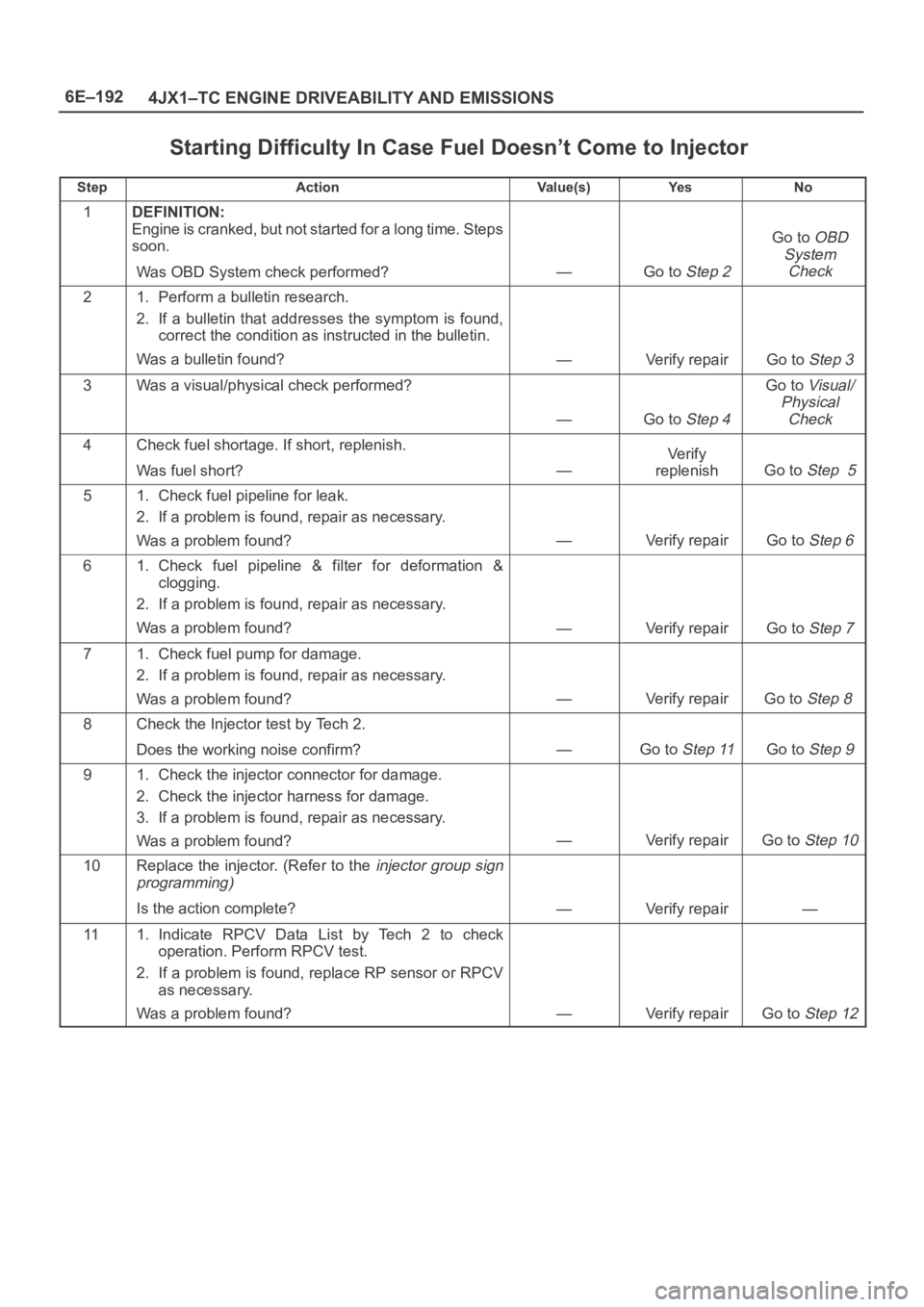
Starting Difficulty In Case Fuel Doesn’t Come to Injector
StepActionVa l u e ( s )Ye sNo
1DEFINITION:
Engine is cranked, but not started for a long time. Steps
soon.
Was OBD System check performed?
—Go to Step 2
Go to OBD
System
Check
21. Perform a bulletin research.
2. If a bulletin that addresses the symptom is found,
correct the condition as instructed in the bulletin.
Was a bulletin found?
—Verify repairGo to Step 3
3Was a visual/physical check performed?
—Go to Step 4
Go to Visual/
Physical
Check
4Check fuel shortage. If short, replenish.
Was fuel short?
—
Ve r i f y
replenish
Go to Step 5
51. Check fuel pipeline for leak.
2. If a problem is found, repair as necessary.
Was a problem found?
—Verify repairGo to Step 6
61. Check fuel pipeline & filter for deformation &
clogging.
2. If a problem is found, repair as necessary.
Was a problem found?
—Verify repairGo to Step 7
71. Check fuel pump for damage.
2. If a problem is found, repair as necessary.
Was a problem found?
—Verify repairGo to Step 8
8Check the Injector test by Tech 2.
Does the working noise confirm?
—Go to Step 11Go to Step 9
91. Check the injector connector for damage.
2. Check the injector harness for damage.
3. If a problem is found, repair as necessary.
Was a problem found?
—Verify repairGo to Step 10
10Replace the injector. (Refer to the injector group sign
programming)
Is the action complete?—Verify repair—
111. Indicate RPCV Data List by Tech 2 to check
operation. Perform RPCV test.
2. If a problem is found, replace RP sensor or RPCV
as necessary.
Was a problem found?
—Verify repairGo to Step 12
Page 2092 of 6000
6E–199 4JX1–TC ENGINE DRIVEABILITY AND EMISSIONS
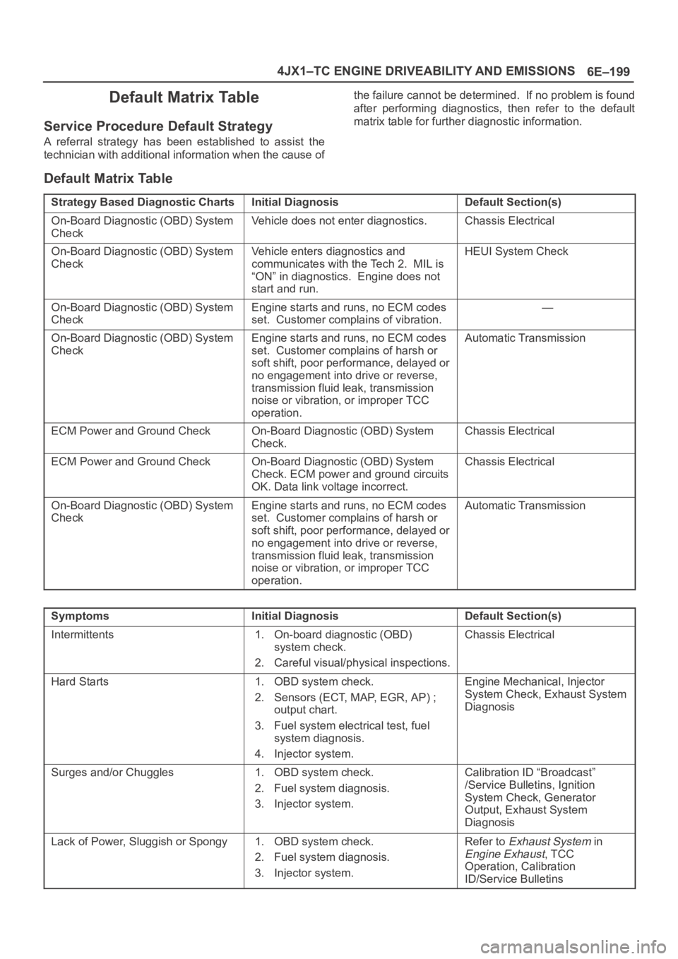
Default Matrix Table
Service Procedure Default Strategy
A referral strategy has been established to assist the
technician with additional information when the cause ofthe failure cannot be determined. If no problem is found
after performing diagnostics, then refer to the default
matrix table for further diagnostic information.
Default Matrix Table
Strategy Based Diagnostic ChartsInitial DiagnosisDefault Section(s)
On-Board Diagnostic (OBD) System
CheckVehicle does not enter diagnostics.Chassis Electrical
On-Board Diagnostic (OBD) System
CheckVehicle enters diagnostics and
communicates with the Tech 2. MIL is
“ON” in diagnostics. Engine does not
start and run.HEUI System Check
On-Board Diagnostic (OBD) System
CheckEngine starts and runs, no ECM codes
set. Customer complains of vibration.—
On-Board Diagnostic (OBD) System
CheckEngine starts and runs, no ECM codes
set. Customer complains of harsh or
soft shift, poor performance, delayed or
no engagement into drive or reverse,
transmission fluid leak, transmission
noise or vibration, or improper TCC
operation.Automatic Transmission
ECM Power and Ground CheckOn-Board Diagnostic (OBD) System
Check.Chassis Electrical
ECM Power and Ground CheckOn-Board Diagnostic (OBD) System
Check. ECM power and ground circuits
OK. Data link voltage incorrect.Chassis Electrical
On-Board Diagnostic (OBD) System
CheckEngine starts and runs, no ECM codes
set. Customer complains of harsh or
soft shift, poor performance, delayed or
no engagement into drive or reverse,
transmission fluid leak, transmission
noise or vibration, or improper TCC
operation.Automatic Transmission
SymptomsInitial DiagnosisDefault Section(s)
Intermittents1. On-board diagnostic (OBD)
system check.
2. Careful visual/physical inspections.Chassis Electrical
Hard Starts1. OBD system check.
2. Sensors (ECT, MAP, EGR, AP) ;
output chart.
3. Fuel system electrical test, fuel
system diagnosis.
4. Injector system.Engine Mechanical, Injector
System Check, Exhaust System
Diagnosis
Surges and/or Chuggles1. OBD system check.
2. Fuel system diagnosis.
3. Injector system.Calibration ID “Broadcast”
/Service Bulletins, Ignition
System Check, Generator
Output, Exhaust System
Diagnosis
Lack of Power, Sluggish or Spongy1. OBD system check.
2. Fuel system diagnosis.
3. Injector system.Refer to Exhaust System in
Engine Exhaust, TCC
Operation, Calibration
ID/Service Bulletins
Page 2094 of 6000
6E–201 4JX1–TC ENGINE DRIVEABILITY AND EMISSIONS
On–Vehicle Service
Camshaft Position (CMP)
Sensor
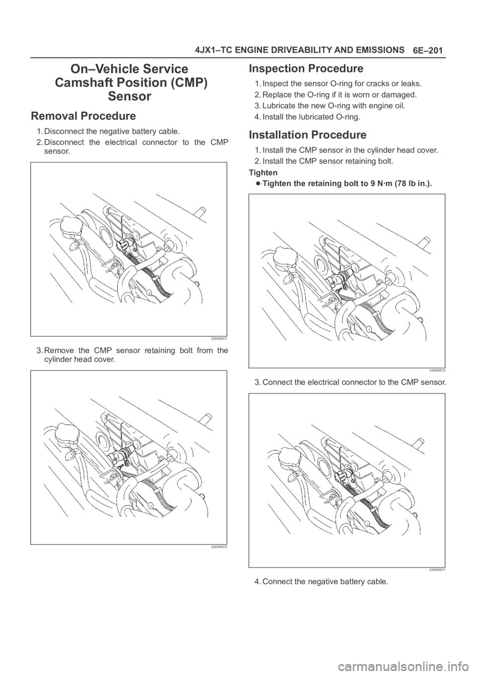
Removal Procedure
1. Disconnect the negative battery cable.
2. Disconnect the electrical connector to the CMP
sensor.
035RW071
3. Remove the CMP sensor retaining bolt from the
cylinder head cover.
035RW075
Inspection Procedure
1. Inspect the sensor O-ring for cracks or leaks.
2. Replace the O-ring if it is worn or damaged.
3. Lubricate the new O-ring with engine oil.
4. Install the lubricated O-ring.
Installation Procedure
1. Install the CMP sensor in the cylinder head cover.
2. Install the CMP sensor retaining bolt.
Tighten
Tighten the retaining bolt to 9 Nꞏm (78 lb in.).
035RW075
3. Connect the electrical connector to the CMP sensor.
035RW071
4. Connect the negative battery cable.
Page 2095 of 6000
6E–202
4JX1–TC ENGINE DRIVEABILITY AND EMISSIONS
Crankshaft Position (CKP)
Sensor
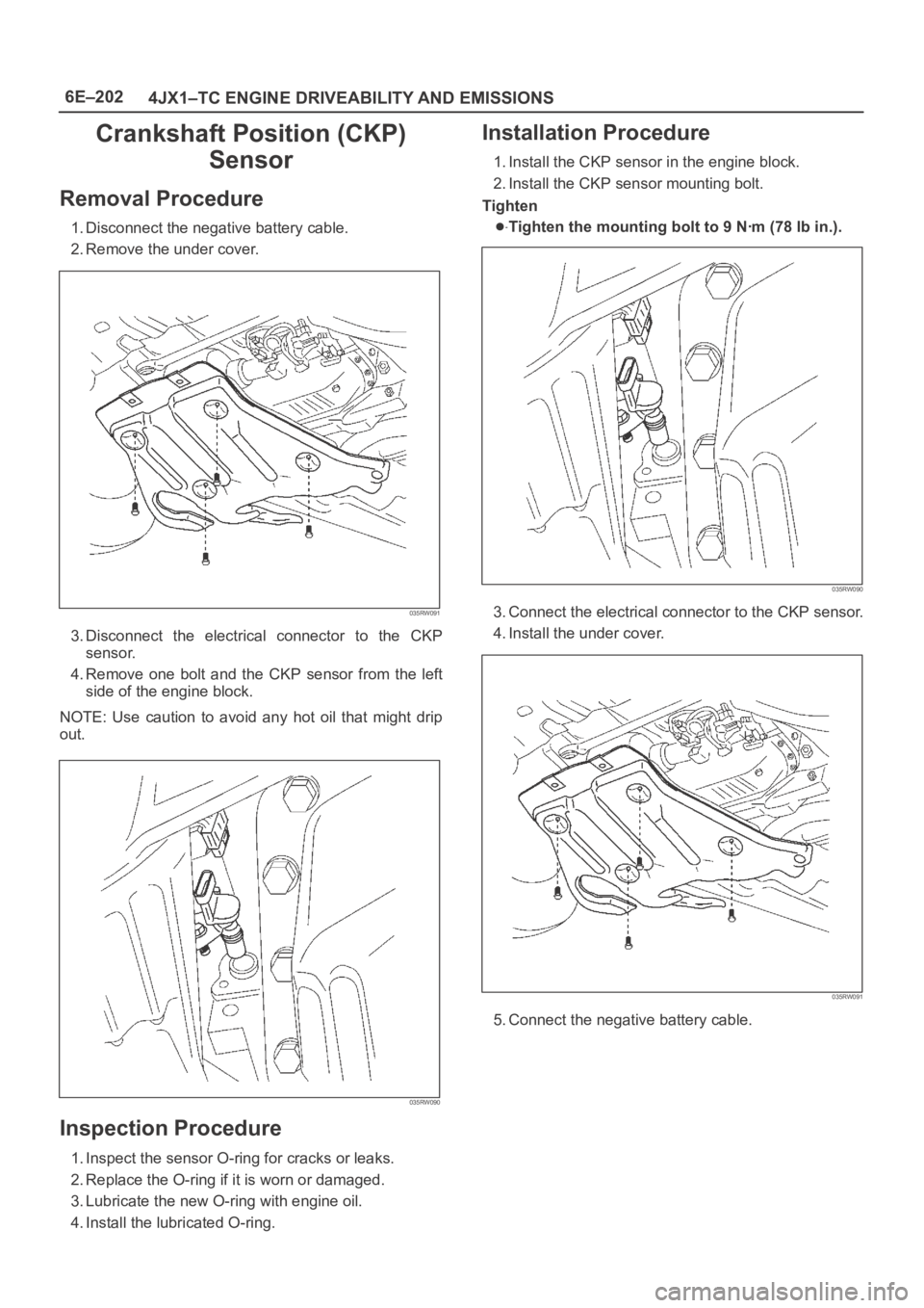
Removal Procedure
1. Disconnect the negative battery cable.
2. Remove the under cover.
035RW091
3. Disconnect the electrical connector to the CKP
sensor.
4. Remove one bolt and the CKP sensor from the left
side of the engine block.
NOTE: Use caution to avoid any hot oil that might drip
out.
035RW090
Inspection Procedure
1. Inspect the sensor O-ring for cracks or leaks.
2. Replace the O-ring if it is worn or damaged.
3. Lubricate the new O-ring with engine oil.
4. Install the lubricated O-ring.
Installation Procedure
1. Install the CKP sensor in the engine block.
2. Install the CKP sensor mounting bolt.
Tighten
Tighten the mounting bolt to 9 Nꞏm (78 lb in.).
035RW090
3. Connect the electrical connector to the CKP sensor.
4. Install the under cover.
035RW091
5. Connect the negative battery cable.
Page 2096 of 6000
6E–203 4JX1–TC ENGINE DRIVEABILITY AND EMISSIONS
Engine Coolant Temperature
(ECT) Sensor
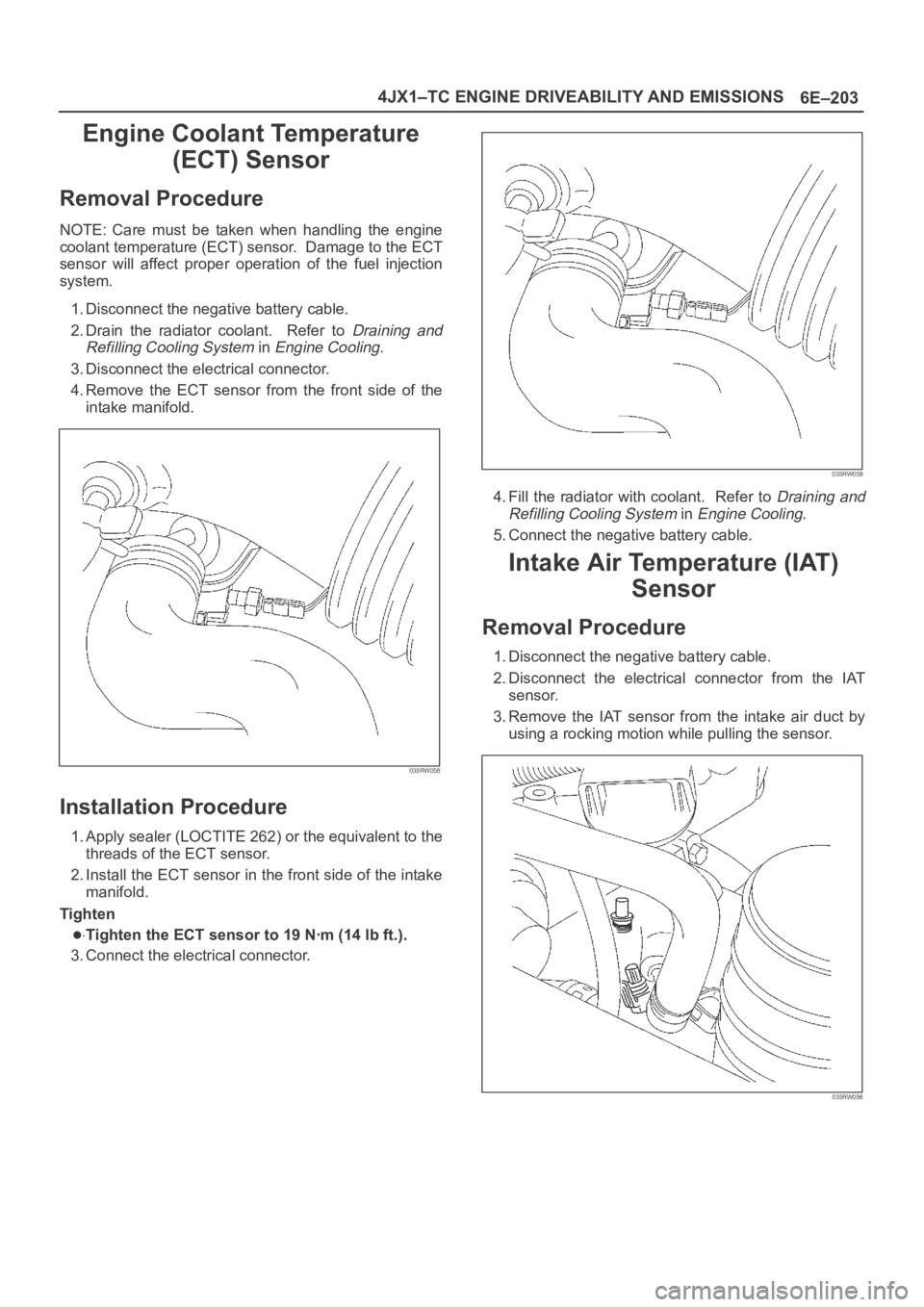
Removal Procedure
NOTE: Care must be taken when handling the engine
coolant temperature (ECT) sensor. Damage to the ECT
sensor will affect proper operation of the fuel injection
system.
1. Disconnect the negative battery cable.
2. Drain the radiator coolant. Refer to
Draining and
Refilling Cooling System
in Engine Cooling.
3. Disconnect the electrical connector.
4.Remove the ECT sensor from the front side of the
intake manifold.
035RW058
Installation Procedure
1. Apply sealer (LOCTITE 262) or the equivalent to the
threads of the ECT sensor.
2. Install the ECT sensor in the front side of the intake
manifold.
Tighten
Tighten the ECT sensor to 19 Nꞏm (14 lb ft.).
3. Connect the electrical connector.
035RW058
4. Fill the radiator with coolant. Refer to Draining and
Refilling Cooling System
in Engine Cooling.
5. Connect the negative battery cable.
Intake Air Temperature (IAT)
Sensor
Removal Procedure
1. Disconnect the negative battery cable.
2. Disconnect the electrical connector from the IAT
sensor.
3. Remove the IAT sensor from the intake air duct by
using a rocking motion while pulling the sensor.
035RW056