1998 OPEL FRONTERA sensor
[x] Cancel search: sensorPage 2041 of 6000
6E–148
4JX1–TC ENGINE DRIVEABILITY AND EMISSIONS
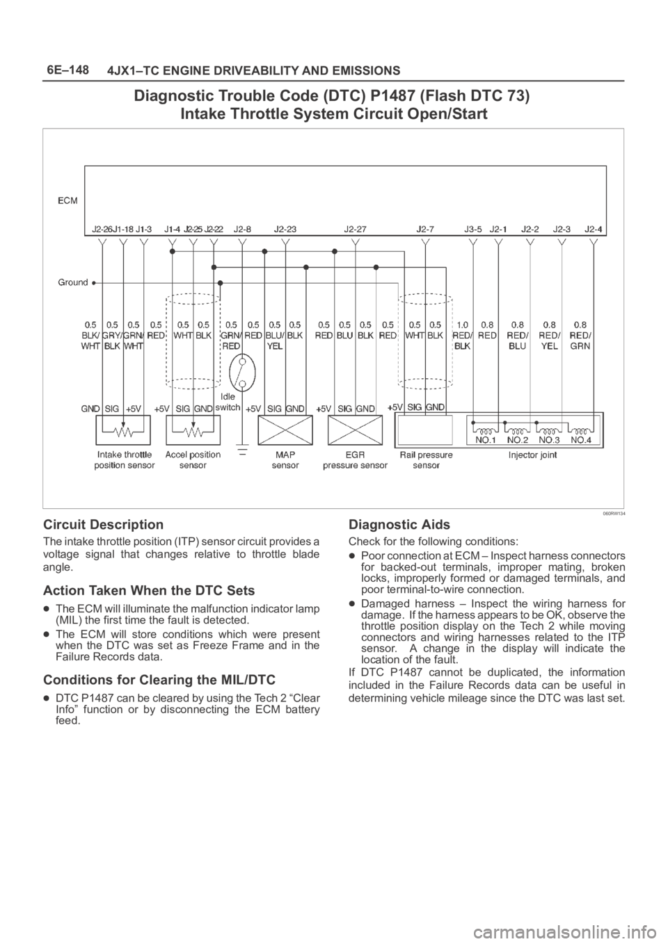
Diagnostic Trouble Code (DTC) P1487 (Flash DTC 73)
Intake Throttle System Circuit Open/Start
060RW134
Circuit Description
The intake throttle position (ITP) sensor circuit provides a
voltage signal that changes relative to throttle blade
angle.
Action Taken When the DTC Sets
The ECM will illuminate the malfunction indicator lamp
(MIL) the first time the fault is detected.
The ECM will store conditions which were present
when the DTC was set as Freeze Frame and in the
Failure Records data.
Conditions for Clearing the MIL/DTC
DTC P1487 can be cleared by using the Tech 2 “Clear
Info” function or by disconnecting the ECM battery
feed.
Diagnostic Aids
Check for the following conditions:
Poor connection at ECM – Inspect harness connectors
for backed-out terminals, improper mating, broken
locks, improperly formed or damaged terminals, and
poor terminal-to-wire connection.
Damaged harness – Inspect the wiring harness for
damage. If the harness appears to be OK, observe the
throttle position display on the Tech 2 while moving
connectors and wiring harnesses related to the ITP
sensor. A change in the display will indicate the
location of the fault.
If DTC P1487 cannot be duplicated, the information
included in the Failure Records data can be useful in
determining vehicle mileage since the DTC was last set.
Page 2043 of 6000
6E–150
4JX1–TC ENGINE DRIVEABILITY AND EMISSIONS
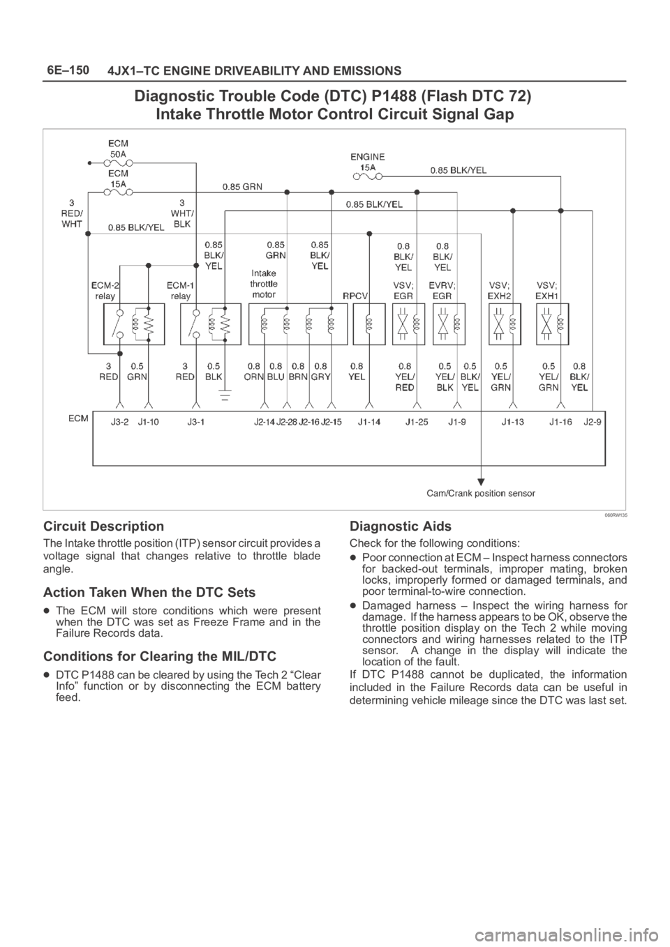
Diagnostic Trouble Code (DTC) P1488 (Flash DTC 72)
Intake Throttle Motor Control Circuit Signal Gap
060RW135
Circuit Description
The Intake throttle position (ITP) sensor circuit provides a
voltage signal that changes relative to throttle blade
angle.
Action Taken When the DTC Sets
The ECM will store conditions which were present
when the DTC was set as Freeze Frame and in the
Failure Records data.
Conditions for Clearing the MIL/DTC
DTC P1488 can be cleared by using the Tech 2 “Clear
Info” function or by disconnecting the ECM battery
feed.
Diagnostic Aids
Check for the following conditions:
Poor connection at ECM – Inspect harness connectors
for backed-out terminals, improper mating, broken
locks, improperly formed or damaged terminals, and
poor terminal-to-wire connection.
Damaged harness – Inspect the wiring harness for
damage. If the harness appears to be OK, observe the
throttle position display on the Tech 2 while moving
connectors and wiring harnesses related to the ITP
sensor. A change in the display will indicate the
location of the fault.
If DTC P1488 cannot be duplicated, the information
included in the Failure Records data can be useful in
determining vehicle mileage since the DTC was last set.
Page 2044 of 6000
6E–151 4JX1–TC ENGINE DRIVEABILITY AND EMISSIONS
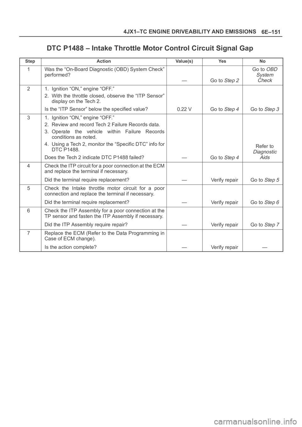
DTC P1488 – Intake Throttle Motor Control Circuit Signal Gap
StepActionVa l u e ( s )Ye sNo
1Was the “On-Board Diagnostic (OBD) System Check”
performed?
—Go to Step 2
Go to OBD
System
Check
21. Ignition “ON,” engine “OFF.”
2. With the throttle closed, observe the “ITP Sensor”
display on the Tech 2.
Is the “ITP Sensor” below the specified value?
0.22 VGo to Step 4Go to Step 3
31. Ignition “ON,” engine “OFF.”
2. Review and record Tech 2 Failure Records data.
3. Operate the vehicle within Failure Records
conditions as noted.
4. Using a Tech 2, monitor the “Specific DTC” info for
DTC P1488.
Does the Tech 2 indicate DTC P1488 failed?
—Go to Step 4
Refer to
Diagnostic
Aids
4Check the ITP circuit for a poor connection at the ECM
and replace the terminal if necessary.
Did the terminal require replacement?
—Verify repairGo to Step 5
5Check the Intake throttle motor circuit for a poor
connection and replace the terminal if necessary.
Did the terminal require replacement?
—Verify repairGo to Step 6
6Check the ITP Assembly for a poor connection at the
TP sensor and fasten the ITP Assembly if necessary.
Did the ITP Assembly require repair?
—Verify repairGo to Step 7
7Replace the ECM (Refer to the Data Programming in
Case of ECM change).
Is the action complete?
—Verify repair—
Page 2045 of 6000
6E–152
4JX1–TC ENGINE DRIVEABILITY AND EMISSIONS
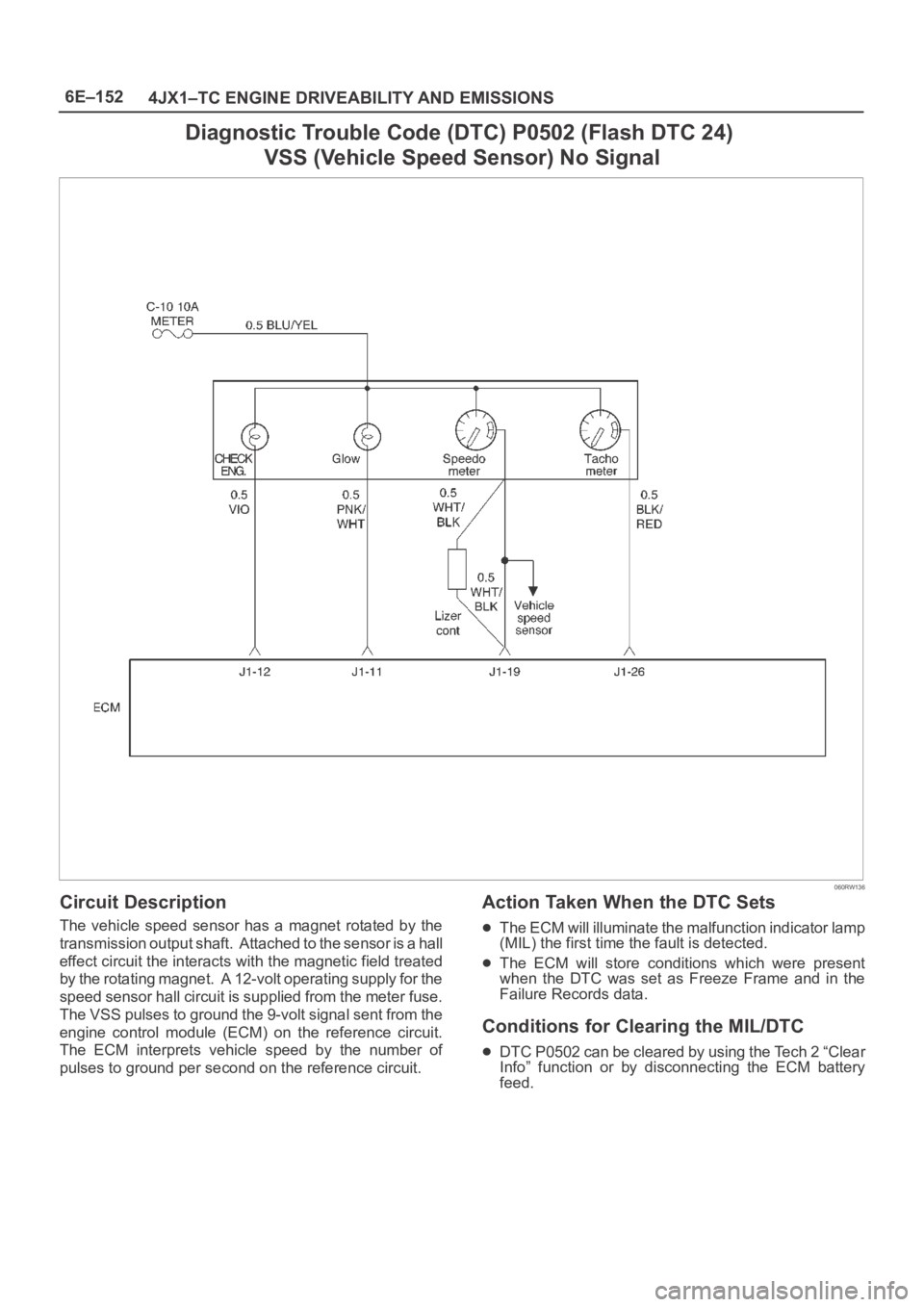
Diagnostic Trouble Code (DTC) P0502 (Flash DTC 24)
VSS (Vehicle Speed Sensor) No Signal
060RW136
Circuit Description
The vehicle speed sensor has a magnet rotated by the
transmission output shaft. Attached to the sensor is a hall
effect circuit the interacts with the magnetic field treated
by the rotating magnet. A 12-volt operating supply for the
speed sensor hall circuit is supplied from the meter fuse.
The VSS pulses to ground the 9-volt signal sent from the
engine control module (ECM) on the reference circuit.
The ECM interprets vehicle speed by the number of
pulses to ground per second on the reference circuit.
Action Taken When the DTC Sets
The ECM will illuminate the malfunction indicator lamp
(MIL) the first time the fault is detected.
The ECM will store conditions which were present
when the DTC was set as Freeze Frame and in the
Failure Records data.
Conditions for Clearing the MIL/DTC
DTC P0502 can be cleared by using the Tech 2 “Clear
Info” function or by disconnecting the ECM battery
feed.
Page 2046 of 6000
6E–153 4JX1–TC ENGINE DRIVEABILITY AND EMISSIONS
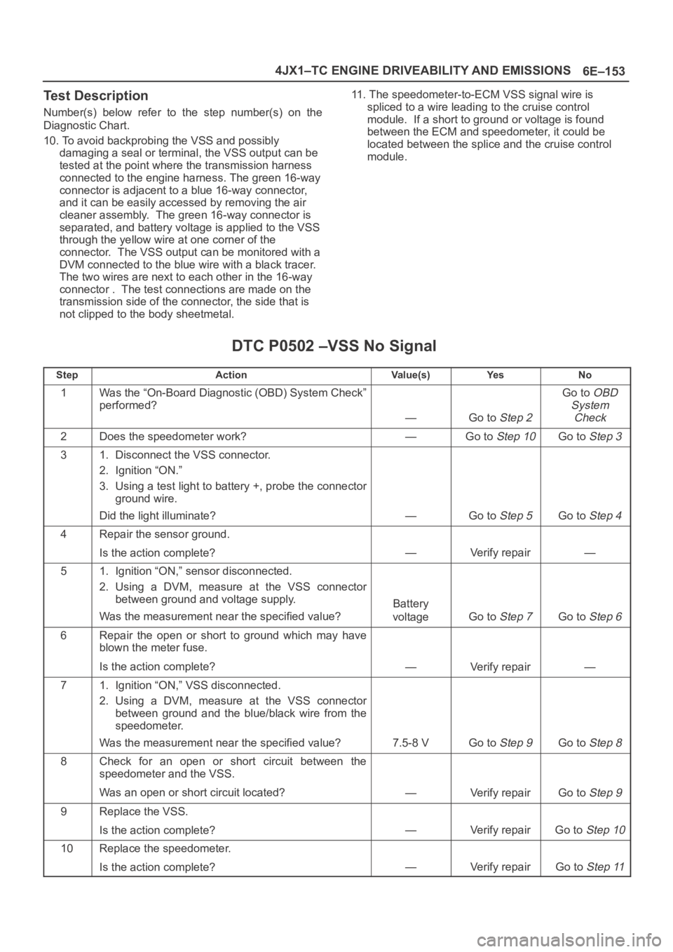
Test Description
Number(s) below refer to the step number(s) on the
Diagnostic Chart.
10. To avoid backprobing the VSS and possibly
damaging a seal or terminal, the VSS output can be
tested at the point where the transmission harness
connected to the engine harness. The green 16-way
connector is adjacent to a blue 16-way connector,
and it can be easily accessed by removing the air
cleaner assembly. The green 16-way connector is
separated, and battery voltage is applied to the VSS
through the yellow wire at one corner of the
connector. The VSS output can be monitored with a
DVM connected to the blue wire with a black tracer.
The two wires are next to each other in the 16-way
connector . The test connections are made on the
transmission side of the connector, the side that is
not clipped to the body sheetmetal.11. The speedometer-to-ECM VSS signal wire is
spliced to a wire leading to the cruise control
module. If a short to ground or voltage is found
between the ECM and speedometer, it could be
located between the splice and the cruise control
module.
DTC P0502 –VSS No Signal
StepActionVa l u e ( s )Ye sNo
1Was the “On-Board Diagnostic (OBD) System Check”
performed?
—Go to Step 2
Go to OBD
System
Check
2Does the speedometer work?—Go to Step 10Go to Step 3
31. Disconnect the VSS connector.
2. Ignition “ON.”
3. Using a test light to battery +, probe the connector
ground wire.
Did the light illuminate?
—Go to Step 5Go to Step 4
4Repair the sensor ground.
Is the action complete?
—Verify repair—
51. Ignition “ON,” sensor disconnected.
2. Using a DVM, measure at the VSS connector
between ground and voltage supply.
Was the measurement near the specified value?
Battery
voltage
Go to Step 7Go to Step 6
6Repair the open or short to ground which may have
blown the meter fuse.
Is the action complete?
—Verify repair—
71. Ignition “ON,” VSS disconnected.
2. Using a DVM, measure at the VSS connector
between ground and the blue/black wire from the
speedometer.
Was the measurement near the specified value?
7.5-8 VGo to Step 9Go to Step 8
8Check for an open or short circuit between the
speedometer and the VSS.
Was an open or short circuit located?
—Verify repairGo to Step 9
9Replace the VSS.
Is the action complete?
—Verify repairGo to Step 10
10Replace the speedometer.
Is the action complete?
—Verify repairGo to Step 11
Page 2067 of 6000
6E–174
4JX1–TC ENGINE DRIVEABILITY AND EMISSIONS
Diagnostic Trouble Code (DTC) P1589 (Flash DTC 47)
Transmission SW Circuit Open/Short
060RW131
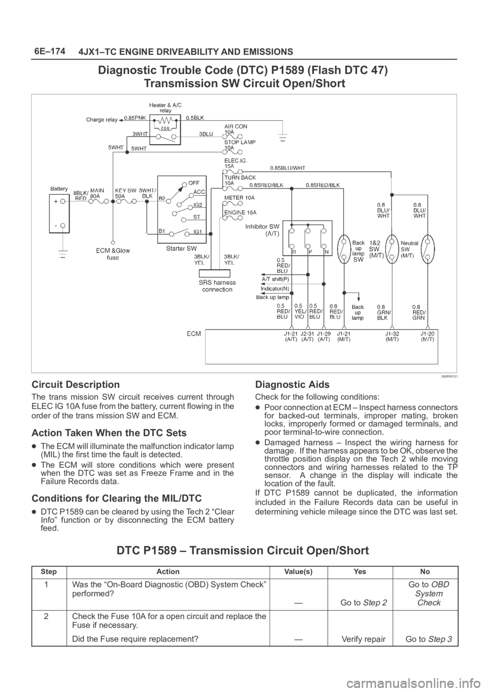
Circuit Description
The trans mission SW circuit receives current through
ELEC IG 10A fuse from the battery, current flowing in the
order of the trans mission SW and ECM.
Action Taken When the DTC Sets
The ECM will illuminate the malfunction indicator lamp
(MIL) the first time the fault is detected.
The ECM will store conditions which were present
when the DTC was set as Freeze Frame and in the
Failure Records data.
Conditions for Clearing the MIL/DTC
DTC P1589 can be cleared by using the Tech 2 “Clear
Info” function or by disconnecting the ECM battery
feed.
Diagnostic Aids
Check for the following conditions:
Poor connection at ECM – Inspect harness connectors
for backed-out terminals, improper mating, broken
locks, improperly formed or damaged terminals, and
poor terminal-to-wire connection.
Damaged harness – Inspect the wiring harness for
damage. If the harness appears to be OK, observe the
throttle position display on the Tech 2 while moving
connectors and wiring harnesses related to the TP
sensor. A change in the display will indicate the
location of the fault.
If DTC P1589 cannot be duplicated, the information
included in the Failure Records data can be useful in
determining vehicle mileage since the DTC was last set.
DTC P1589 – Transmission Circuit Open/Short
StepActionVa l u e ( s )Ye sNo
1Was the “On-Board Diagnostic (OBD) System Check”
performed?
—Go to Step 2
Go to OBD
System
Check
2Check the Fuse 10A for a open circuit and replace the
Fuse if necessary.
Did the Fuse require replacement?
—Verify repairGo to Step 3
Page 2069 of 6000
6E–176
4JX1–TC ENGINE DRIVEABILITY AND EMISSIONS
Symptom Diagnosis
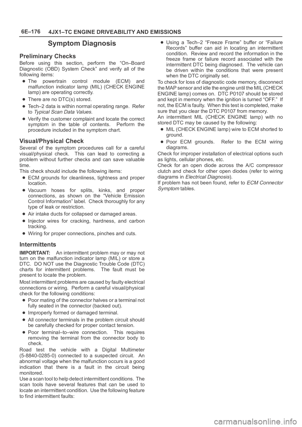
Preliminary Checks
Before using this section, perform the “On–Board
Diagnostic (OBD) System Check” and verify all of the
following items:
The powertrain control module (ECM) and
malfunction indicator lamp (MIL) (CHECK ENGINE
lamp) are operating correctly.
There are no DTC(s) stored.
Tech–2 data is within normal operating range. Refer
to
Typical Scan Data Values.
Verify the customer complaint and locate the correct
symptom in the table of contents. Perform the
procedure included in the symptom chart.
Visual/Physical Check
Several of the symptom procedures call for a careful
visual/physical check. This can lead to correcting a
problem without further checks and can save valuable
time.
This check should include the following items:
ECM grounds for cleanliness, tightness and proper
location.
Vacuum hoses for splits, kinks, and proper
connections, as shown on the “Vehicle Emission
Control Information” label. Check thoroughly for any
type of leak or restriction.
Air intake ducts for collapsed or damaged areas.
Injector wires for cracking, hardness, and carbon
tracking.
Wiring for proper connections, pinches and cuts.
Intermittents
IMPORTANT:An intermittent problem may or may not
turn on the malfunction indicator lamp (MIL) or store a
DTC. DO NOT use the Diagnostic Trouble Code (DTC)
charts for intermittent problems. The fault must be
present to locate the problem.
Most intermittent problems are caused by faulty electrical
connections or wiring. Perform a careful visual/physical
check for the following conditions:
Poor mating of the connector halves or a terminal not
fully seated in the connector (backed out).
Improperly formed or damaged terminal.
All connector terminals in the problem circuit should
be carefully checked for proper contact tension.
Poor terminal–to–wire connection. This requires
removing the terminal from the connector body to
check.
Road test the vehicle with a Digital Multimeter
(5-8840-0285-0) connected to a suspected circuit. An
abnormal voltage when the malfunction occurs is a good
indication that there is a fault in the circuit being
monitored.
Use a scan tool to help detect intermittent conditions. The
scan tools have several features that can be used to
locate an intermittent condition. Use the following feature
to find intermittent faults:
Using a Tech–2 “Freeze Frame” buffer or “Failure
Records” buffer can aid in locating an intermittent
condition. Review and record the information in the
freeze frame or failure record associated with the
intermittent DTC being diagnosed. The vehicle can
be driven within the conditions that were present
when the DTC originally set.
To check for loss of diagnostic code memory, disconnect
the MAP sensor and idle the engine until the MIL (CHECK
ENGINE lamp) comes on. DTC P0107 should be stored
and kept in memory when the ignition is turned “OFF.” If
not, the ECM is faulty. When this test is completed, make
sure that you clear the DTC P0107 from memory.
An intermittent MIL (CHECK ENGINE lamp) with no
stored DTC may be caused by the following:
MIL (CHECK ENGINE lamp) wire to ECM shorted to
ground.
Poor ECM grounds. Refer to the ECM wiring
diagrams.
Check for improper installation of electrical options such
as lights, cellular phones, etc.
Check for an open diode across the A/C compressor
clutch and check for other open diodes (refer to wiring
diagrams in
Electrical Diagnosis).
If problem has not been found, refer to
ECM Connector
Symptom
tables.
Page 2070 of 6000
6E–177 4JX1–TC ENGINE DRIVEABILITY AND EMISSIONS
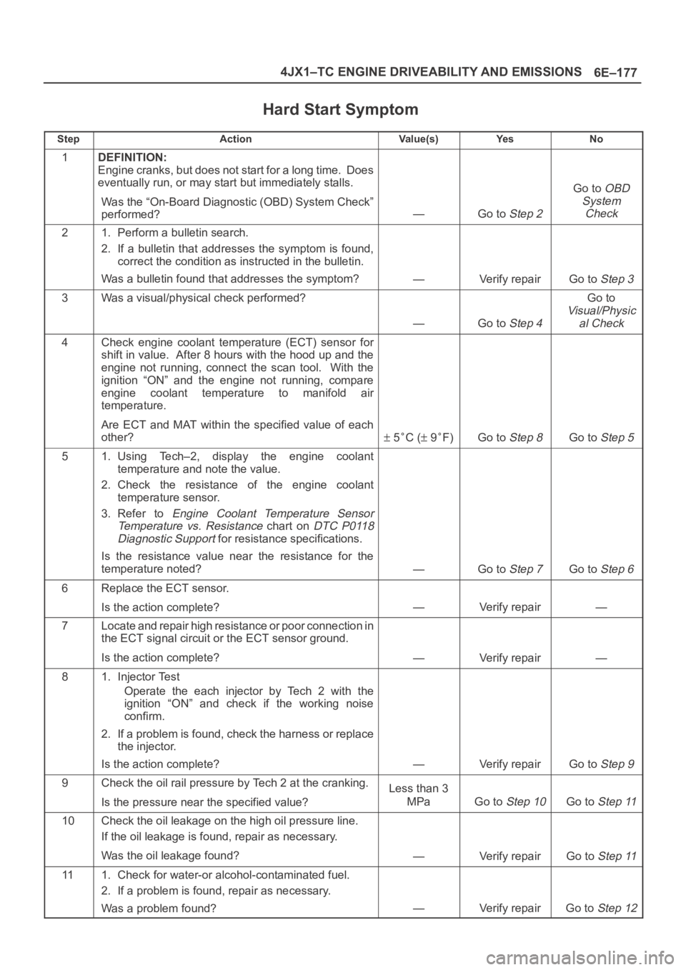
Hard Start Symptom
StepActionVa l u e ( s )Ye sNo
1DEFINITION:
Engine cranks, but does not start for a long time. Does
eventually run, or may start but immediately stalls.
Was the “On-Board Diagnostic (OBD) System Check”
performed?
—Go to Step 2
Go to OBD
System
Check
21. Perform a bulletin search.
2. If a bulletin that addresses the symptom is found,
correct the condition as instructed in the bulletin.
Was a bulletin found that addresses the symptom?
—Verify repairGo to Step 3
3Was a visual/physical check performed?
—Go to Step 4
Go to
Visual/Physic
al Check
4Check engine coolant temperature (ECT) sensor for
shift in value. After 8 hours with the hood up and the
engine not running, connect the scan tool. With the
ignition “ON” and the engine not running, compare
engine coolant temperature to manifold air
temperature.
Are ECT and MAT within the specified value of each
other?
5C ( 9F)Go to Step 8Go to Step 5
51. Using Tech–2, display the engine coolant
temperature and note the value.
2. Check the resistance of the engine coolant
temperature sensor.
3. Refer to
Engine Coolant Temperature Sensor
Temperature vs. Resistance
chart on DTC P0118
Diagnostic Support
for resistance specifications.
Is the resistance value near the resistance for the
temperature noted?
—Go to Step 7Go to Step 6
6Replace the ECT sensor.
Is the action complete?
—Verify repair—
7Locate and repair high resistance or poor connection in
the ECT signal circuit or the ECT sensor ground.
Is the action complete?
—Verify repair—
81. Injector Test
Operate the each injector by Tech 2 with the
ignition “ON” and check if the working noise
confirm.
2. If a problem is found, check the harness or replace
the injector.
Is the action complete?
—Verify repairGo to Step 9
9Check the oil rail pressure by Tech 2 at the cranking.
Is the pressure near the specified value?Less than 3
MPa
Go to Step 10Go to Step 11
10Check the oil leakage on the high oil pressure line.
If the oil leakage is found, repair as necessary.
Was the oil leakage found?
—Verify repairGo to Step 11
111. Check for water-or alcohol-contaminated fuel.
2. If a problem is found, repair as necessary.
Was a problem found?
—Verify repairGo to Step 12