Page 2182 of 6000

7A–28
AUTOMATIC TRANSMISSION (4L30–E)
Removal
1. Disconnect battery ground cable.
2. Remove transfer control lever knob.
3. Remove front console.
Disconnect wiring harness connectors from front
console.
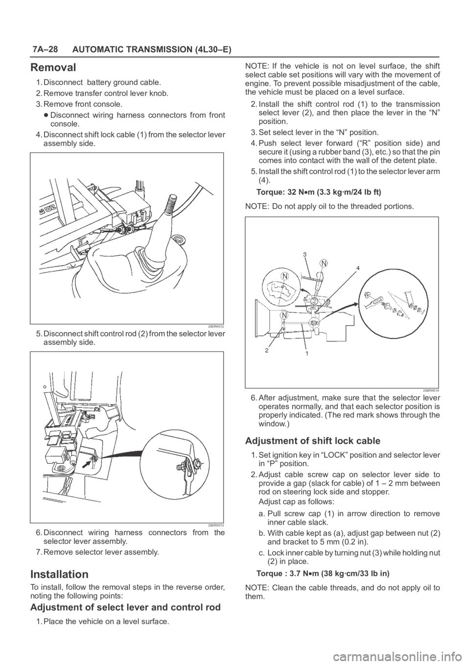
4. Disconnect shift lock cable (1) from the selector lever
assembly side.
256RW012
5. Disconnect shift control rod (2) from the selector lever
assembly side.
256RW013
6. Disconnect wiring harness connectors from the
selector lever assembly.
7. Remove selector lever assembly.
Installation
To install, follow the removal steps in the reverse order,
noting the following points:
Adjustment of select lever and control rod
1. Place the vehicle on a level surface.NOTE: If the vehicle is not on level surface, the shift
select cable set positions will vary with the movement of
engine. To prevent possible misadjustment of the cable,
the vehicle must be placed on a level surface.
2. Install the shift control rod (1) to the transmission
select lever (2), and then place the lever in the “N”
position.
3. Set select lever in the “N” position.
4. Push select lever forward (“R” position side) and
s e c u r e i t ( u s i n g a r u b b e r b a n d ( 3 ) , e t c . ) s o t h a t t h e p i n
comes into contact with the wall of the detent plate.
5. Install the shift control rod (1) to the selector lever arm
(4).
To r q u e : 3 2 N
m (3.3 kgꞏm/24 lb ft)
NOTE: Do not apply oil to the threaded portions.
256RW014
6. After adjustment, make sure that the selector lever
operates normally, and that each selector position is
properly indicated. (The red mark shows through the
window.)
Adjustment of shift lock cable
1. Set ignition key in “LOCK” position and selector lever
in “P” position.
2. Adjust cable screw cap on selector lever side to
provide a gap (slack for cable) of 1 – 2 mm between
rod on steering lock side and stopper.
Adjust cap as follows:
a. Pull screw cap (1) in arrow direction to remove
inner cable slack.
b. With cable kept as (a), adjust gap between nut (2)
and bracket to 5 mm (0.2 in).
c. Lock inner cable by turning nut (3) while holding nut
(2) in place.
Torque : 3.7 N
m (38 kgꞏcm/33 lb in)
NOTE: Clean the cable threads, and do not apply oil to
them.
Page 2556 of 6000
LIGHTING SYSTEM8A–17
Starter Switch
Removal
1. Disconnect the battery ground cable.
2. Remove the front console assembly(1).
Refer to Instrument Panel Assembly in Body
Structure section.
3. Remove the lower cluster assembly(2).
Refer to the Instrument Panel Assembly in Body
Structure section.
4. Remove the instrument panel driver lower cover
assembly(3).
Refer to the Instrument Panel Assembly in Body
Structure section.
821RW024
5. Remove seven screws to remove the steering
cowl(6).
6. Disconnect the connector, remove the screw(4) and
then remove the starter switch(5).
431RW005
Installation
To install, follow the removal steps in the reverse order
noting the following point.
1. When installing the steering cowl(10), be sure to pass
the harnesses through the route as shown in the
figure so that the starter switch harness(7), the
combination switch harness(8) and the inflator
module harness(9) will not get caught.
431RW008
Page 2557 of 6000

8A–18LIGHTING SYSTEM
Lighting Switch (Combination Switch)
Removal
1. Disconnect the battery ground cable.
2. Remove the instrument panel driver lower cover(5).
Refer to the Instrument Panel Assembly in Body
Structure section.
3. Remove seven screws to remove the steering
cowl(4).
4. Disconnect the SDM (air bag controller) connector
located at lower of the instrument panel driver lower
cover.
5. Remove four fixing screws and disconnect the driver
inflator module connector to remove the driver inflator
module(3).
CAUTION: When carrying a live inflator module,
make sure the bag opening is pointed away from
y o u . I n c a s e o f a n a c c i d e n t a l d e p l o y m e n t , t h e b a g w i l l
then deploy with minimal chance of injury. Never
carry the inflator module by the wires or connector
on the underside of the module.
When placing a live inflator module on a bench or
other surface, always face the bag and trim cover up,
away from the surface. This is necessary so that a
free space is provided to allow the air bag to expand
in the unlikely event of accidental deployment.
6. Remove the steering wheel(2).
Refer to the Steering Wheel in Steering section.
7. Disconnect the SRS coil assembly connector,
remove four fixing screws to remove the SRS coil
assembly(1).
8. Disconnect the lighting switch connector, remove four
fixing screws to remove the lighting switch(6).
825RS039
Installation
To install, follow the removal steps in the reverse order,
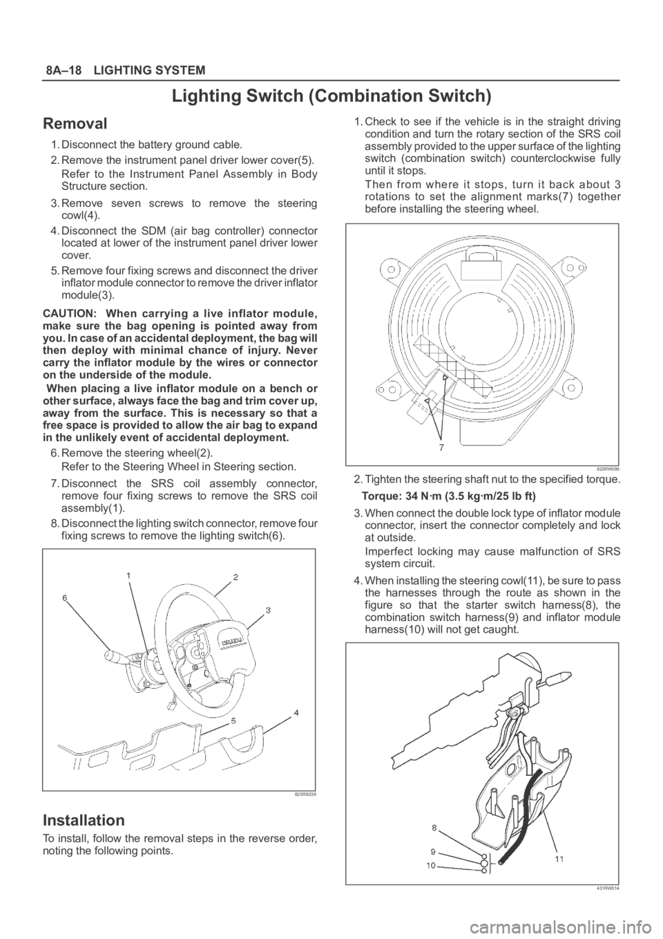
noting the following points.1. Check to see if the vehicle is in the straight driving
condition and turn the rotary section of the SRS coil
assembly provided to the upper surface of the lighting
switch (combination switch) counterclockwise fully
until it stops.
Then from where it stops, turn it back about 3
rotations to set the alignment marks(7) together
before installing the steering wheel.
825RW099
2. Tighten the steering shaft nut to the specified torque.
Torque: 34 Nꞏm (3.5 kgꞏm/25 lb ft)
3. When connect the double lock type of inflator module
connector, insert the connector completely and lock
at outside.
Imperfect locking may cause malfunction of SRS
system circuit.
4. When installing the steering cowl(11), be sure to pass
the harnesses through the route as shown in the
figure so that the starter switch harness(8), the
combination switch harness(9) and inflator module
harness(10) will not get caught.
431RW014
Page 2569 of 6000
8A–30LIGHTING SYSTEM
Power drive1.4w1Meter
Winter drive1.4w1Meter
Air bag2w1Meter
Engine warming SW0.84w1
FRT fog light SW0.84w1
RR fog light SW0.84w1
Glove box1.2w1
Ashtray1.4w1
Illumination controller0.7w1
Heater bezel150mA2
Hazard warning light SW0.84w1
Meter3.4w4Meter ASM
IlluminationCigar lighter1.4w1Light
Rear wiper & washer SW0.84w1
Rear defogger SW0.84w1
Mirror control SW45mA1
Mirror defogger SW0.7w1
Mirror folding SW0.7w1
A/T select lever1.2w1
Power & Winter SW50mA2
Cruise control main SW0.84w1
Headlight wiper SW0.84w1
Torque Specifications
ApplicationNꞏmkgꞏmLb FtLb In
Steering Shaft Nut343.525—
Page 2675 of 6000
PCM : POWERTRAIN CONTROL MODULE
P C M
0.5
B
1.0
B/L 0.5
R/W
0.5
R/WX-111C-397 7
3X-11C-3 E13
FUEL PUMP
RELAY
FUEL
PUMP
F-10 15A
FUEL PUMPF-2 20A
OXYGEN SENSOR
HEATER
JOINT
CONNECTOR
KNOCK
SENSOR
2.0
B2.0
B 2.0
B/R2.0
B/R2.0
B/R2.0
B/R 2.0
R2.0
R1.25
B/L0.85
B/L
0.85
R/W
FENDER-RH2.0
WF-4
2H-4620H-332H-1315X-114
2X-11
1F-4
H-5
C-88
1410
16
E-30C-2C9
C-2C7
COMMON CHAMBER
R-4
BODY-RR
1.25
B/P
1.0
B/R1.25
B/P
0.5
B0.5
Y
0.5
Y
H-513E-29C-2C8
COMMON CHAMBER
H-613
1C-1E-14A2
POWER
STEERING
PRESSURE
SW
0.5
G/Y
0.5
G/YH-616
1C-1E-4 B11
H-42
13
H-33
D08RW588
Page 2690 of 6000
PCM : POWERTRAIN CONTROL MODULE
P C M
0.5
B
1.0
B/L 0.5
R/W
0.5
R/WX-111C-397 7
3X-11C-3 E13
FUEL PUMP
RELAY
FUEL
PUMP
F-10 15A
FUEL PUMPF-2 20A
OXYGEN SENSOR
HEATER
JOINT
CONNECTOR
KNOCK
SENSOR
2.0
B2.0
B 2.0
B/R2.0
B/R2.0
B/R2.0
B/R 2.0
R2.0
R1.25
B/L0.85
B/L
0.85
R/W
FENDER-RH2.0
WF-4
2H-4620H-338H-135X-114
2X-11
1F-4
H-5
C-88
1410
16
E-30C-2C9
C-2C7
COMMON CHAMBER
R-4
BODY-RR
1.25
B/P
1.0
B/R1.25
B/P
0.5
B0.5
Y
0.5
Y
H-513E-29C-2C8
COMMON CHAMBER
H-613
1C-1E-14A2
POWER
STEERING
PRESSURE
SW
0.5
G/Y
0.5
G/YH-616
1C-1E-4 B11
H-42
7
H-33
D08RW902
Page 3249 of 6000

8F–54BODY STRUCTURE
Cross Beam Assembly
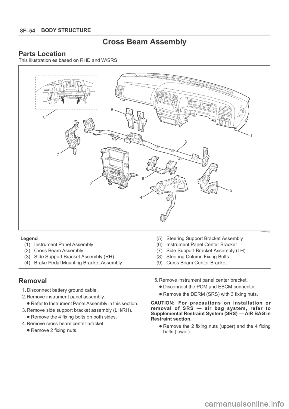
Parts Location
This illustration es based on RHD and W/SRS
740RW100
Legend
(1) Instrument Panel Assembly
(2) Cross Beam Assembly
(3) Side Support Bracket Assembly (RH)
(4) Brake Pedal Mounting Bracket Assembly(5) Steering Support Bracket Assembly
(6) Instrument Panel Center Bracket
(7) Side Support Bracket Assembly (LH)
(8) Steering Column Fixing Bolts
(9) Cross Beam Center Bracket
Removal
1. Disconnect battery ground cable.
2. Remove instrument panel assembly.
Refer to Instrument Panel Assembly in this section.
3. Remove side support bracket assembly (LH/RH).
Remove the 4 fixing bolts on both sides.
4. Remove cross beam center bracket
Remove 2 fixing nuts.5. Remove instrument panel center bracket.
Disconnect the PCM and EBCM connector.
Remove the DERM (SRS) with 3 fixing nuts.
CAUTION: For precautions on installation or
removal of SRS — air bag system, refer to
Supplemental Restraint System (SRS) — AIR BAG in
Restraint section.
Remove the 2 fixing nuts (upper) and the 4 fixing
bolts (lower).
Page 3250 of 6000
8F–55 BODY STRUCTURE
740RW101
6. Remove steering column fixing bolts.
Remove 2 fixing bolts.
431RW007
7. Remove brake pedal mounting bracket assembly.
Disconnect the 2 brake pedal mounting bracket
assembly fixing nuts, and remove the antitheft
controller.
Disconnect the brake pedal link and the brake
switch, and remove the 4 fixing bolts and the nuts
on the bracket.
310RW014
8. Remove steering support bracket assembly.
Remove the 2 fixing bolts (upper side) (1) and the 3
fixing nuts (lower side) (2).
740RW102
9. Remove cross beam assembly.
Disconnect the harness clips from the crossbeam
assembly, and remove 2 fixing bolts on both sides
and 2 fixing nuts in the center.
Installation
To install, follow the removal steps in the reverse order.