1998 OPEL FRONTERA steering
[x] Cancel search: steeringPage 3485 of 6000
SUPPLEMENTAL RESTRAINT SYSTEM 9J–48
Passenger Air Bag Assembly
Service Precautions
WARNING: SAFETY PRECAUTIONS MUST BE
FOLLOWED WHEN HANDLING A DEPLOYED AIR
BAG ASSEMBLY. AFTER DEPLOYMENT, THE AIR
BAG ASSEMBLY SURFACE MAY CONTAIN A SMALL
AMOUNT OF SODIUM HYDROXIDE, A BY–PRODUCT
OF THE DEPLOYMENT REACTION, THAT IS
IRRITATING TO THE SKIN AND EYES. MOST OF THE
POWER ON THE AIR BAG ASSEMBLY IS
HARMLESS. AS A PRECAUTION, WEAR GLOVES
AND SAFETY GLASSES WHEN HANDLING A
DEPLOYED AIR BAG ASSEMBLY, AND WASH YOUR
HANDS WITH MILD SOAP AND WATER
AFTERWARDS.
WARNING: WHEN CARRYING A LIVE AIR BAG
ASSEMBLY, MAKE SURE THE BAG AND TRIM
COVER ARE POINTED AWAY FROM YOU. NEVER
CARRY AIR BAG ASSEMBLY BY THE WIRES OR
CONNECTOR ON THE UNDERSIDE OF MODULE. IN
THE CASE OF AN ACCIDENTAL DEPLOYMENT, THE
BAG WILL THEN DEPLOY WITH MINIMAL CHANCE
OF INJURY. WHEN PLACING ALIVE AIR BAG
ASSEMBLY ON A BENCH OR OTHER SURFACE,
ALWAYS FACE BAG AND RIM COVER UP, AWAY
FROM THE SURFACE. NEVER REST A STEERING
COLUMN ASSEMBLY ON THE STEERING WHEEL
WITH THE AIR BAG ASSEMBLY FACE DOWN AND
COLUMN VERTICAL. THIS IS NECESSARY SO THAT
A FREE SPACE IS PROVIDED TO ALLOW THE AIR
BAG ASSEMBLY TO EXPAND IN THE UNLIKELY
EVENT OF ACCIDENTAL DEPLOYMENT.
OTHERWISE, PERSONAL INJURY COULD RESULT.
NOTE: IN THE EVENT DEPLOYMENT HAS
OCCURRED, INSPECT COIL ASSEMBLY WIRE FOR
ANY SIGNS OF SCORCHING, MELTING OR ANY
OTHER DAMAGE DUE TO EXCESSIVE HEAT. IF THE
COIL HAS BEEN DAMAGED, REPLACE IT.
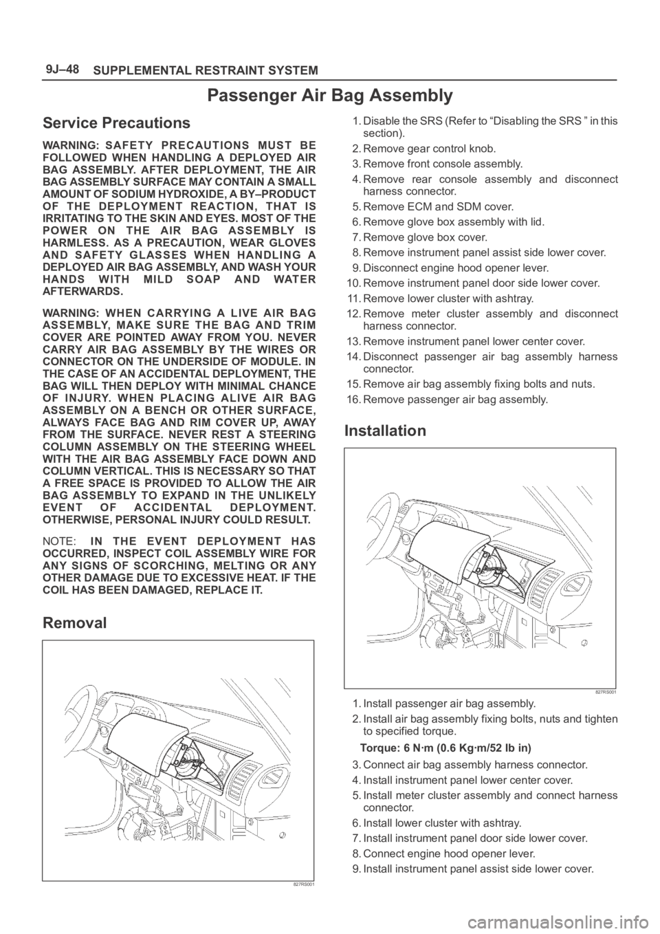
Removal
827RS001
1. Disable the SRS (Refer to “Disabling the SRS ” in this
section).
2. Remove gear control knob.
3. Remove front console assembly.
4. Remove rear console assembly and disconnect
harness connector.
5. Remove ECM and SDM cover.
6. Remove glove box assembly with lid.
7. Remove glove box cover.
8. Remove instrument panel assist side lower cover.
9. Disconnect engine hood opener lever.
10. Remove instrument panel door side lower cover.
11. Remove lower cluster with ashtray.
12. Remove meter cluster assembly and disconnect
harness connector.
13. Remove instrument panel lower center cover.
14. Disconnect passenger air bag assembly harness
connector.
15. Remove air bag assembly fixing bolts and nuts.
16. Remove passenger air bag assembly.
Installation
827RS001
1. Install passenger air bag assembly.
2. Install air bag assembly fixing bolts, nuts and tighten
to specified torque.
Torque: 6 Nꞏm (0.6 Kgꞏm/52 Ib in)
3. Connect air bag assembly harness connector.
4. Install instrument panel lower center cover.
5. Install meter cluster assembly and connect harness
connector.
6. Install lower cluster with ashtray.
7. Install instrument panel door side lower cover.
8. Connect engine hood opener lever.
9. Install instrument panel assist side lower cover.
Page 3487 of 6000
SUPPLEMENTAL RESTRAINT SYSTEM 9J–50
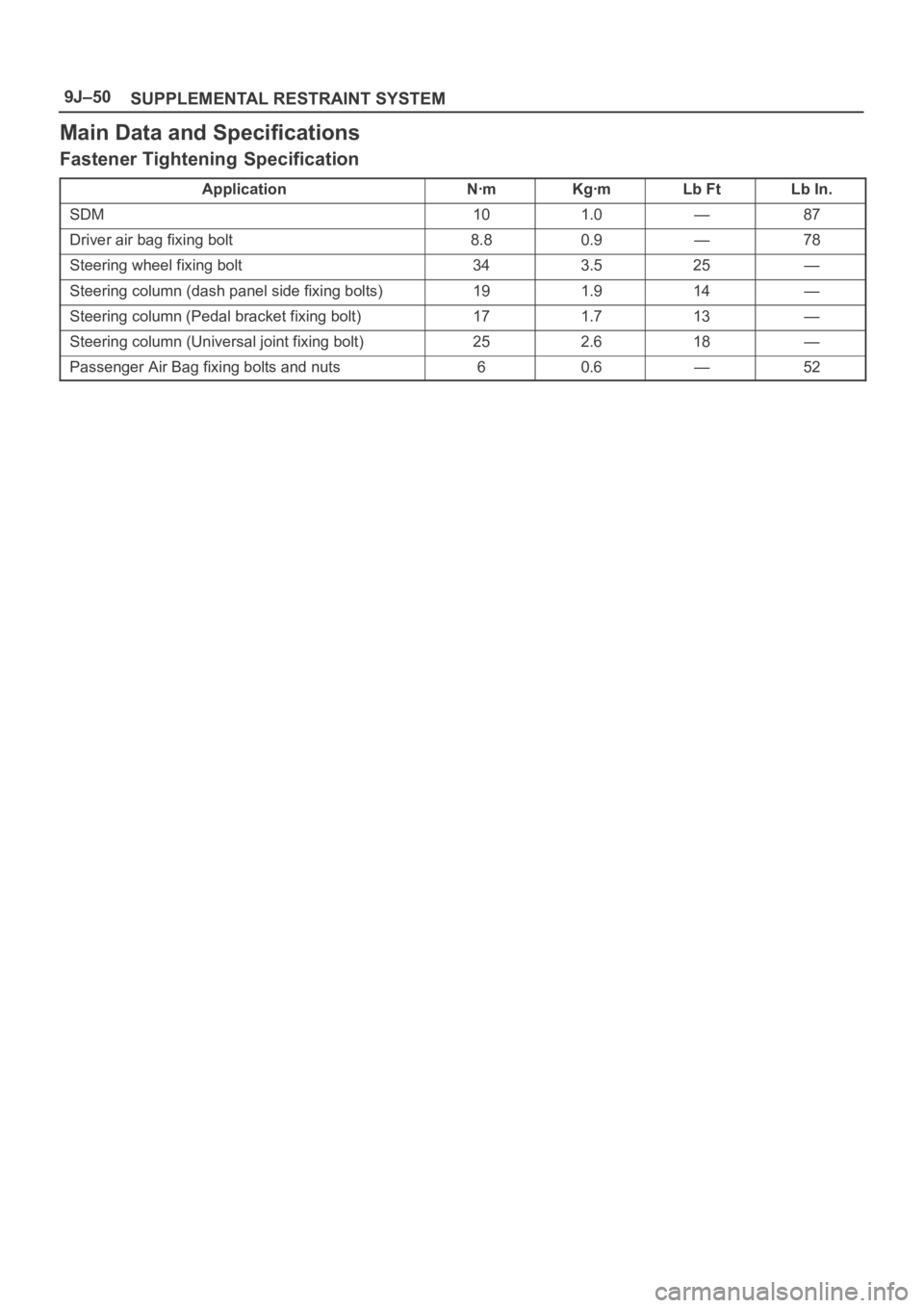
Main Data and Specifications
Fastener Tightening Specification
ApplicationNꞏmKgꞏmLb FtLb In.
SDM101.0—87
Driver air bag fixing bolt8.80.9—78
Steering wheel fixing bolt343.525—
Steering column (dash panel side fixing bolts)191.914—
Steering column (Pedal bracket fixing bolt)171.713—
Steering column (Universal joint fixing bolt)252.618—
Passenger Air Bag fixing bolts and nuts60.6—52
Page 3496 of 6000
9J1–9
RESTRAINT CONTROL SYSTEM
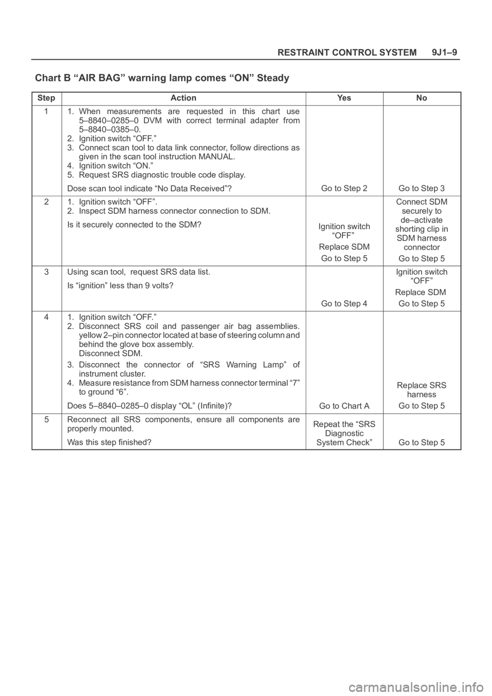
Chart B “AIR BAG” warning lamp comes “ON” Steady
StepActionYe sNo
11. When measurements are requested in this chart use
5–8840–0285–0 DVM with correct terminal adapter from
5–8840–0385–0.
2. Ignition switch “OFF.”
3. Connect scan tool to data link connector, follow directions as
given in the scan tool instruction MANUAL.
4. Ignition switch “ON.”
5. Request SRS diagnostic trouble code display.
Dose scan tool indicate “No Data Received”?
Go to Step 2Go to Step 3
21. Ignition switch “OFF”.
2. Inspect SDM harness connector connection to SDM.
Is it securely connected to the SDM?
Ignition switch
“OFF”
Replace SDM
Go to Step 5
Connect SDM
securely to
de–activate
shorting clip in
SDM harness
connector
Go to Step 5
3Using scan tool, request SRS data list.
Is “ignition” less than 9 volts?
Go to Step 4
Ignition switch
“OFF”
Replace SDM
Go to Step 5
41. Ignition switch “OFF.”
2. Disconnect SRS coil and passenger air bag assemblies.
yellow 2–pin connector located at base of steering column and
behind the glove box assembly.
Disconnect SDM.
3. Disconnect the connector of “SRS Warning Lamp” of
instrument cluster.
4. Measure resistance from SDM harness connector terminal “7”
to ground “6”.
Does 5–8840–0285–0 display “OL” (Infinite)?
Go to Chart A
Replace SRS
harness
Go to Step 5
5Reconnect all SRS components, ensure all components are
properly mounted.
Was this step finished?Repeat the “SRS
Diagnostic
System Check”
Go to Step 5
Page 3498 of 6000
9J1–11
RESTRAINT CONTROL SYSTEM
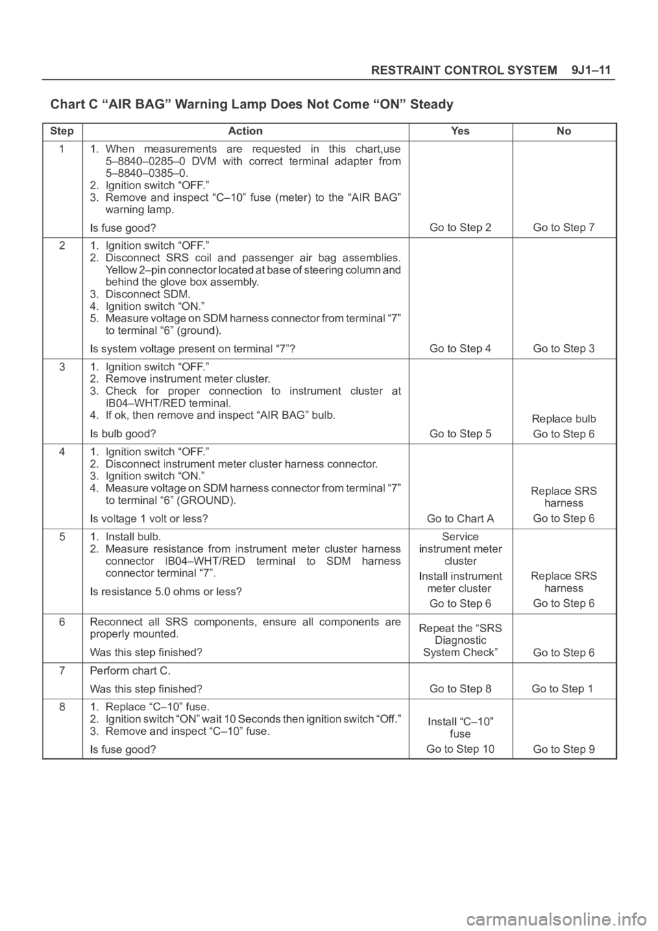
Chart C “AIR BAG” Warning Lamp Does Not Come “ON” Steady
StepActionYe sNo
11. When measurements are requested in this chart,use
5–8840–0285–0 DVM with correct terminal adapter from
5–8840–0385–0.
2. Ignition switch “OFF.”
3. Remove and inspect “C–10” fuse (meter) to the “AIR BAG”
warning lamp.
Is fuse good?
Go to Step 2Go to Step 7
21. Ignition switch “OFF.”
2. Disconnect SRS coil and passenger air bag assemblies.
Yellow 2–pin connector located at base of steering column and
behind the glove box assembly.
3. Disconnect SDM.
4. Ignition switch “ON.”
5. Measure voltage on SDM harness connector from terminal “7”
to terminal “6” (ground).
Is system voltage present on terminal “7”?
Go to Step 4Go to Step 3
31. Ignition switch “OFF.”
2. Remove instrument meter cluster.
3. Check for proper connection to instrument cluster at
IB04–WHT/RED terminal.
4. If ok, then remove and inspect “AIR BAG” bulb.
Is bulb good?
Go to Step 5
Replace bulb
Go to Step 6
41. Ignition switch “OFF.”
2. Disconnect instrument meter cluster harness connector.
3. Ignition switch “ON.”
4. Measure voltage on SDM harness connector from terminal “7”
to terminal “6” (GROUND).
Is voltage 1 volt or less?
Go to Chart A
Replace SRS
harness
Go to Step 6
51. Install bulb.
2. Measure resistance from instrument meter cluster harness
connector IB04–WHT/RED terminal to SDM harness
connector terminal “7”.
Is resistance 5.0 ohms or less?Service
instrument meter
cluster
Install instrument
meter cluster
Go to Step 6
Replace SRS
harness
Go to Step 6
6Reconnect all SRS components, ensure all components are
properly mounted.
Was this step finished?Repeat the “SRS
Diagnostic
System Check”
Go to Step 6
7Perform chart C.
Was this step finished?
Go to Step 8Go to Step 1
81. Replace “C–10” fuse.
2. Ignition switch “ON” wait 10 Seconds then ignition switch “Off.”
3. Remove and inspect “C–10” fuse.
Is fuse good?
Install “C–10”
fuse
Go to Step 10
Go to Step 9
Page 3499 of 6000
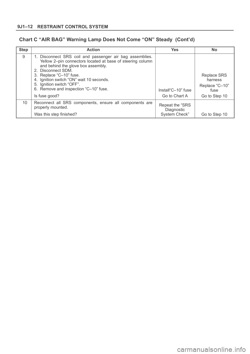
RESTRAINT CONTROL SYSTEM 9J1–12
Chart C “AIR BAG” Warning Lamp Does Not Come “ON” Steady (Cont’d)
StepNo Ye s Action
91. Disconnect SRS coil and passenger air bag assemblies.
Yellow 2–pin connectors located at base of steering column
and behind the glove box assembly.
2. Disconnect SDM.
3. Replace “C–10” fuse.
4. Ignition switch “ON” wait 10 seconds.
5. Ignition switch “OFF”.
6. Remove and inspection “C–10” fuse.
Is fuse good?
Install“C–10” fuse
Go to Chart A
Replace SRS
harness
Replace “C–10”
fuse
Go to Step 10
10Reconnect all SRS components, ensure all components are
properly mounted.
Was this step finished?Repeat the “SRS
Diagnostic
System Check”
Go to Step 10
Page 3501 of 6000
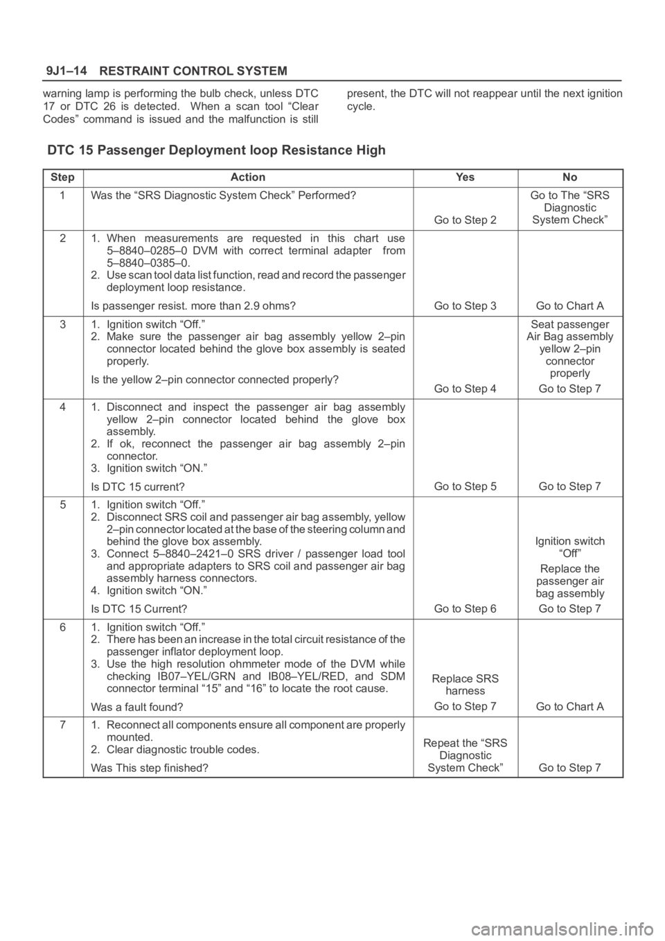
RESTRAINT CONTROL SYSTEM 9J1–14
warning lamp is performing the bulb check, unless DTC
17 or DTC 26 is detected. When a scan tool “Clear
Codes” command is issued and the malfunction is stillpresent, the DTC will not reappear until the next ignition
cycle.
DTC 15 Passenger Deployment loop Resistance High
StepActionYe sNo
1Was the “SRS Diagnostic System Check” Performed?
Go to Step 2
Go to The “SRS
Diagnostic
System Check”
21. When measurements are requested in this chart use
5–8840–0285–0 DVM with correct terminal adapter from
5–8840–0385–0.
2. Use scan tool data list function, read and record the passenger
deployment loop resistance.
Is passenger resist. more than 2.9 ohms?
Go to Step 3Go to Chart A
31. Ignition switch “Off.”
2. Make sure the passenger air bag assembly yellow 2–pin
connector located behind the glove box assembly is seated
properly.
Is the yellow 2–pin connector connected properly?
Go to Step 4
Seat passenger
Air Bag assembly
yellow 2–pin
connector
properly
Go to Step 7
41. Disconnect and inspect the passenger air bag assembly
yellow 2–pin connector located behind the glove box
assembly.
2. If ok, reconnect the passenger air bag assembly 2–pin
connector.
3. Ignition switch “ON.”
Is DTC 15 current?
Go to Step 5Go to Step 7
51. Ignition switch “Off.”
2. Disconnect SRS coil and passenger air bag assembly, yellow
2–pin connector located at the base of the steering column and
behind the glove box assembly.
3. Connect 5–8840–2421–0 SRS driver / passenger load tool
and appropriate adapters to SRS coil and passenger air bag
assembly harness connectors.
4. Ignition switch “ON.”
Is DTC 15 Current?
Go to Step 6
Ignition switch
“Off”
Replace the
passenger air
bag assembly
Go to Step 7
61. Ignition switch “Off.”
2. There has been an increase in the total circuit resistance of t h e
passenger inflator deployment loop.
3. Use the high resolution ohmmeter mode of the DVM while
checking IB07–YEL/GRN and IB08–YEL/RED, and SDM
connector terminal “15” and “16” to locate the root cause.
Was a fault found?
Replace SRS
harness
Go to Step 7
Go to Chart A
71. Reconnect all components ensure all component are properly
mounted.
2. Clear diagnostic trouble codes.
Was This step finished?
Repeat the “SRS
Diagnostic
System Check”
Go to Step 7
Page 3503 of 6000
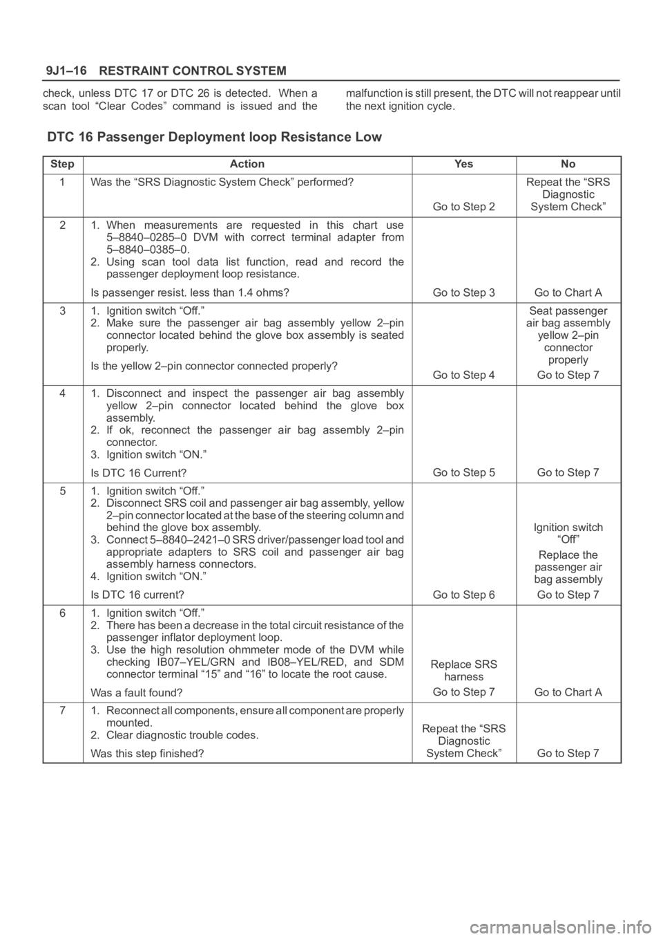
RESTRAINT CONTROL SYSTEM 9J1–16
check, unless DTC 17 or DTC 26 is detected. When a
scan tool “Clear Codes” command is issued and themalfunction is still present, the DTC will not reappear until
the next ignition cycle.
DTC 16 Passenger Deployment loop Resistance Low
StepActionYe sNo
1Was the “SRS Diagnostic System Check” performed?
Go to Step 2
Repeat the “SRS
Diagnostic
System Check”
21. When measurements are requested in this chart use
5–8840–0285–0 DVM with correct terminal adapter from
5–8840–0385–0.
2. Using scan tool data list function, read and record the
passenger deployment loop resistance.
Is passenger resist. less than 1.4 ohms?
Go to Step 3Go to Chart A
31. Ignition switch “Off.”
2. Make sure the passenger air bag assembly yellow 2–pin
connector located behind the glove box assembly is seated
properly.
Is the yellow 2–pin connector connected properly?
Go to Step 4
Seat passenger
air bag assembly
yellow 2–pin
connector
properly
Go to Step 7
41. Disconnect and inspect the passenger air bag assembly
yellow 2–pin connector located behind the glove box
assembly.
2. If ok, reconnect the passenger air bag assembly 2–pin
connector.
3. Ignition switch “ON.”
Is DTC 16 Current?
Go to Step 5Go to Step 7
51. Ignition switch “Off.”
2. Disconnect SRS coil and passenger air bag assembly, yellow
2–pin connector located at the base of the steering column and
behind the glove box assembly.
3. Connect 5–8840–2421–0 SRS driver/passenger load tool and
appropriate adapters to SRS coil and passenger air bag
assembly harness connectors.
4. Ignition switch “ON.”
Is DTC 16 current?
Go to Step 6
Ignition switch
“Off”
Replace the
passenger air
bag assembly
Go to Step 7
61. Ignition switch “Off.”
2. There has been a decrease in the total circuit resistance of the
passenger inflator deployment loop.
3. Use the high resolution ohmmeter mode of the DVM while
checking IB07–YEL/GRN and IB08–YEL/RED, and SDM
connector terminal “15” and “16” to locate the root cause.
Was a fault found?
Replace SRS
harness
Go to Step 7
Go to Chart A
71. Reconnect all components, ensure all component are properly
mounted.
2. Clear diagnostic trouble codes.
Was this step finished?
Repeat the “SRS
Diagnostic
System Check”
Go to Step 7
Page 3505 of 6000
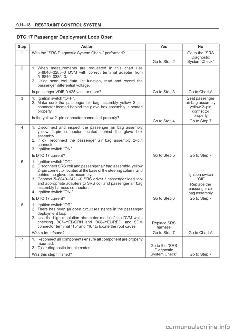
RESTRAINT CONTROL SYSTEM 9J1–18
DTC 17 Passenger Deployment Loop Open
StepActionYe sNo
1Was the “SRS Diagnostic System Check” performed?
Go to Step 2
Go to the “SRS
Diagnostic
System Check”
21. When measurements are requested in this chart use
5–8840–0285–0 DVM with correct terminal adapter from
5–8840–0385–0.
2. Using scan tool data list function, read and record the
passenger differential voltage.
Is passenger VDIF 0.425 volts or more?
Go to Step 3Go to Chart A
31. Ignition switch “OFF”.
2. Make sure the passenger air bag assembly yellow 2–pin
connector located behind the glove box assembly is seated
properly.
Is the yellow 2–pin connector connected properly?
Go to Step 4
Seat passenger
air bag assembly
yellow 2–pin
connector
properly
Go to Step 7
41. Disconnect and inspect the passenger air bag assembly
yellow 2–pin connector located behind the glove box
assembly.
2. If ok, reconnect the passenger air bag assembly 2–pin
connector.
3. Ignition switch “ON”.
Is DTC 17 current?
Go to Step 5Go to Step 7
51. Ignition switch “Off.”
2. Disconnect SRS coil and passenger air bag assembly, yellow
2–pin connector located at the base of the steering column and
behind the glove box assembly.
3. Connect 5–8840–2421–0 SRS driver / passenger load tool
and appropriate adapters to SRS coil and passenger air bag
assembly harness connectors.
4. Ignition switch “ON.”
Is DTC 17 current?
Go to Step 6
Ignition switch
“Off”
Replace the
passenger air
bag assembly
Go to Step 7
61. Ignition switch “Off.”
2. There has been an open circuit resistance in the passenger
deployment loop.
3. Use the high resolution ohmmeter mode of the DVM while
checking IB07–YEL/GRN and IB08–YEL/RED, and SDM
connector terminal “15” and “16” to locate the root cause.
Was a fault found?
Replace SRS
harness
Go to Step 7
Go to Chart A
71. Reconnect all components ensure all component are properly
mounted.
2. Clear diagnostic trouble codes.
Was this step finished?
Go to the “SRS
Diagnostic
System Check”
Go to Step 7