1998 OPEL FRONTERA steering
[x] Cancel search: steeringPage 3518 of 6000
9J1–31
RESTRAINT CONTROL SYSTEM
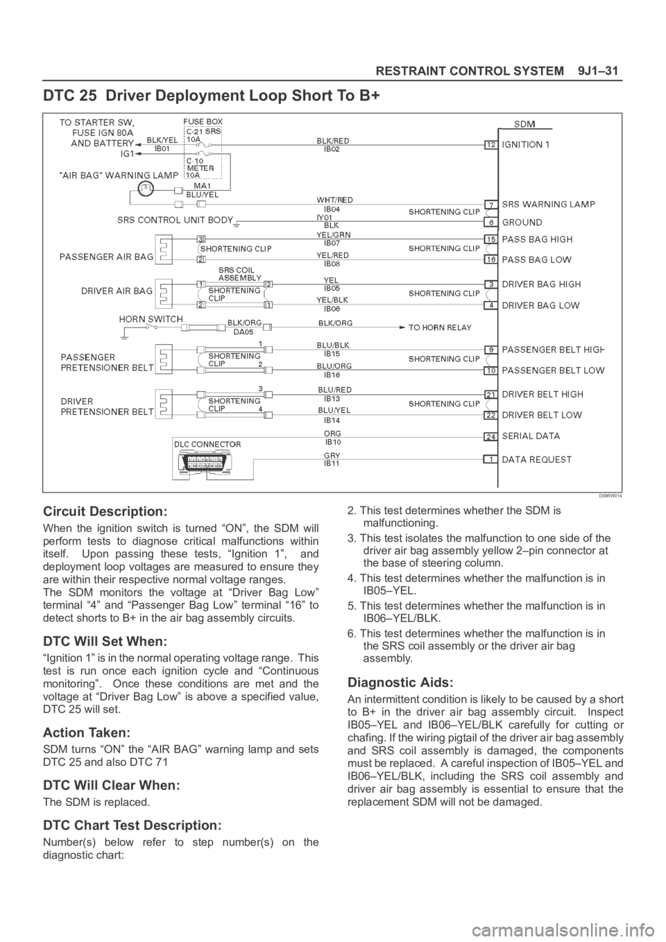
DTC 25 Driver Deployment Loop Short To B+
D09RW014
Circuit Description:
When the ignition switch is turned “ON”, the SDM will
perform tests to diagnose critical malfunctions within
itself. Upon passing these tests, “Ignition 1”, and
deployment loop voltages are measured to ensure they
are within their respective normal voltage ranges.
The SDM monitors the voltage at “Driver Bag Low”
terminal “4” and “Passenger Bag Low” terminal “16” to
detect shorts to B+ in the air bag assembly circuits.
DTC Will Set When:
“Ignition 1” is in the normal operating voltage range. This
test is run once each ignition cycle and “Continuous
monitoring”. Once these conditions are met and the
voltage at “Driver Bag Low” is above a specified value,
DTC 25 will set.
Action Taken:
SDM turns “ON” the “AIR BAG” warning lamp and sets
DTC 25 and also DTC 71
DTC Will Clear When:
The SDM is replaced.
DTC Chart Test Description:
Number(s) below refer to step number(s) on the
diagnostic chart:2. This test determines whether the SDM is
malfunctioning.
3. This test isolates the malfunction to one side of the
driver air bag assembly yellow 2–pin connector at
the base of steering column.
4. This test determines whether the malfunction is in
IB05–YEL.
5. This test determines whether the malfunction is in
IB06–YEL/BLK.
6. This test determines whether the malfunction is in
the SRS coil assembly or the driver air bag
assembly.
Diagnostic Aids:
An intermittent condition is likely to be caused by a short
to B+ in the driver air bag assembly circuit. Inspect
IB05–YEL and IB06–YEL/BLK carefully for cutting or
chafing. If the wiring pigtail of the driver air bag assembly
and SRS coil assembly is damaged, the components
must be replaced. A careful inspection of IB05–YEL and
IB06–YEL/BLK, including the SRS coil assembly and
driver air bag assembly is essential to ensure that the
replacement SDM will not be damaged.
Page 3519 of 6000
RESTRAINT CONTROL SYSTEM 9J1–32
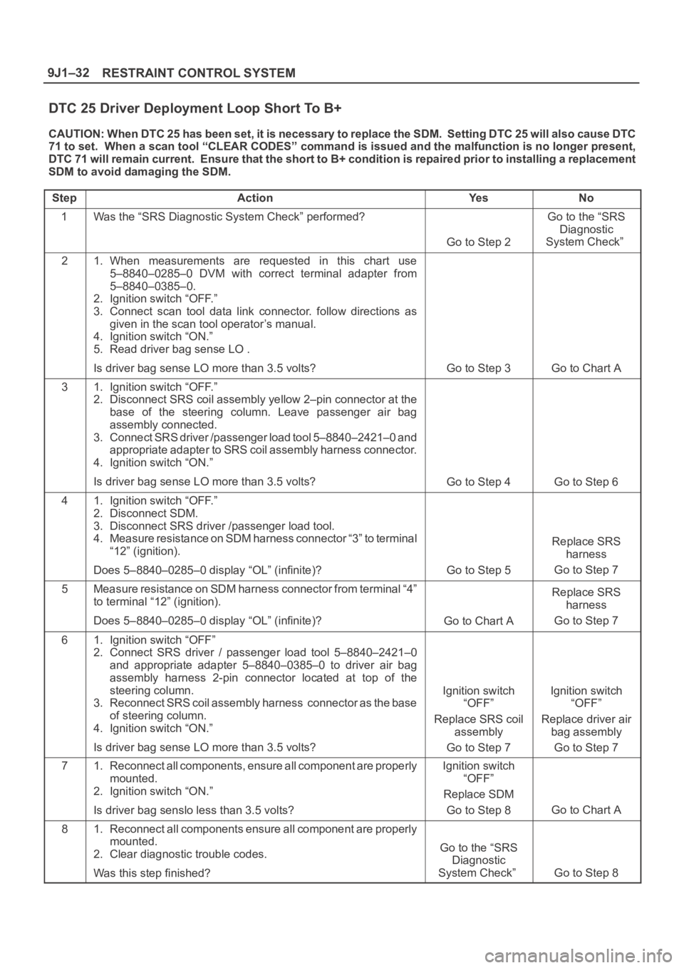
DTC 25 Driver Deployment Loop Short To B+
CAUTION: When DTC 25 has been set, it is necessary to replace the SDM. Setting DTC 25 will also cause DTC
71 to set. When a scan tool “CLEAR CODES” command is issued and the malfunction is no longer present,
DTC 71 will remain current. Ensure that the short to B+ condition is repaired prior to installing a replacement
SDM to avoid damaging the SDM.
Step
ActionYe sNo
1Was the “SRS Diagnostic System Check” performed?
Go to Step 2
Go to the “SRS
Diagnostic
System Check”
21. When measurements are requested in this chart use
5–8840–0285–0 DVM with correct terminal adapter from
5–8840–0385–0.
2. Ignition switch “OFF.”
3. Connect scan tool data link connector. follow directions as
given in the scan tool operator’s manual.
4. Ignition switch “ON.”
5. Read driver bag sense LO .
Is driver bag sense LO more than 3.5 volts?
Go to Step 3Go to Chart A
31. Ignition switch “OFF.”
2. Disconnect SRS coil assembly yellow 2–pin connector at the
base of the steering column. Leave passenger air bag
assembly connected.
3. Connect SRS driver /passenger load tool 5–8840–2421–0 and
appropriate adapter to SRS coil assembly harness connector.
4. Ignition switch “ON.”
Is driver bag sense LO more than 3.5 volts?
Go to Step 4Go to Step 6
41. Ignition switch “OFF.”
2. Disconnect SDM.
3. Disconnect SRS driver /passenger load tool.
4. Measure resistance on SDM harness connector “3” to terminal
“12” (ignition).
Does 5–8840–0285–0 display “OL” (infinite)?
Go to Step 5
Replace SRS
harness
Go to Step 7
5Measure resistance on SDM harness connector from terminal “4”
to terminal “12” (ignition).
Does 5–8840–0285–0 display “OL” (infinite)?
Go to Chart A
Replace SRS
harness
Go to Step 7
61. Ignition switch “OFF”
2. Connect SRS driver / passenger load tool 5–8840–2421–0
and appropriate adapter 5–8840–0385–0 to driver air bag
assembly harness 2-pin connector located at top of the
steering column.
3. Reconnect SRS coil assembly harness connector as the base
of steering column.
4. Ignition switch “ON.”
Is driver bag sense LO more than 3.5 volts?
Ignition switch
“OFF”
Replace SRS coil
assembly
Go to Step 7Ignition switch
“OFF”
Replace driver air
bag assembly
Go to Step 7
71. Reconnect all components, ensure all component are properly
mounted.
2. Ignition switch “ON.”
Is driver bag senslo less than 3.5 volts?Ignition switch
“OFF”
Replace SDM
Go to Step 8
Go to Chart A
81. Reconnect all components ensure all component are properly
mounted.
2. Clear diagnostic trouble codes.
Was this step finished?
Go to the “SRS
Diagnostic
System Check”
Go to Step 8
Page 3520 of 6000
9J1–33
RESTRAINT CONTROL SYSTEM
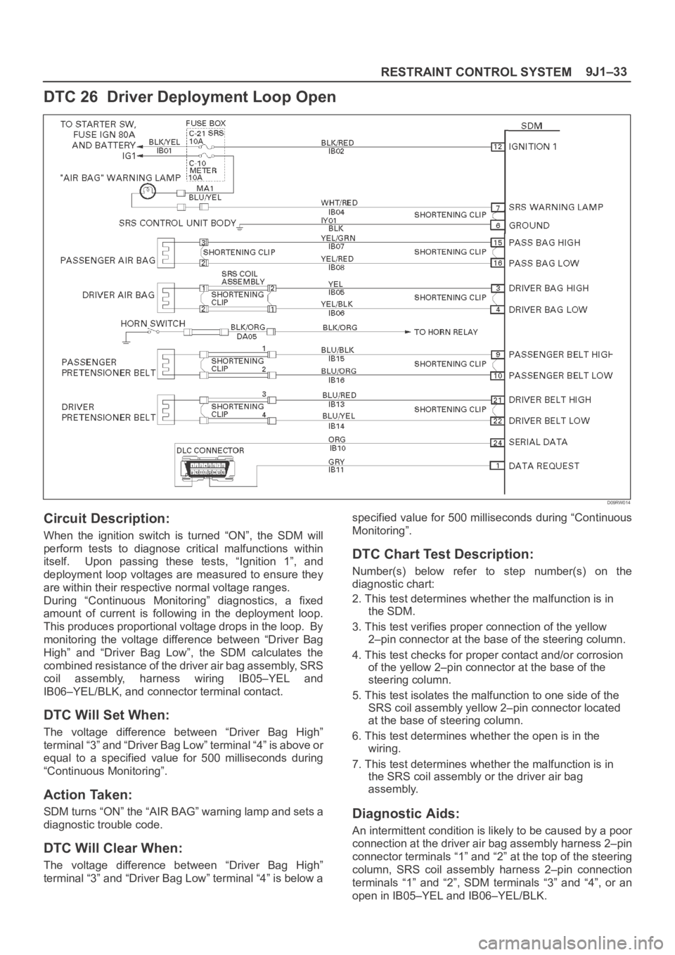
DTC 26 Driver Deployment Loop Open
D09RW014
Circuit Description:
When the ignition switch is turned “ON”, the SDM will
perform tests to diagnose critical malfunctions within
itself. Upon passing these tests, “Ignition 1”, and
deployment loop voltages are measured to ensure they
are within their respective normal voltage ranges.
During “Continuous Monitoring” diagnostics, a fixed
amount of current is following in the deployment loop.
This produces proportional voltage drops in the loop. By
monitoring the voltage difference between “Driver Bag
High” and “Driver Bag Low”, the SDM calculates the
combined resistance of the driver air bag assembly, SRS
coil assembly, harness wiring IB05–YEL and
IB06–YEL/BLK, and connector terminal contact.
DTC Will Set When:
The voltage difference between “Driver Bag High”
terminal “3” and “Driver Bag Low” terminal “4” is above or
equal to a specified value for 500 milliseconds during
“Continuous Monitoring”.
Action Taken:
SDM turns “ON” the “AIR BAG” warning lamp and sets a
diagnostic trouble code.
DTC Will Clear When:
The voltage difference between “Driver Bag High”
terminal “3” and “Driver Bag Low” terminal “4” is below aspecified value for 500 milliseconds during “Continuous
Monitoring”.
DTC Chart Test Description:
Number(s) below refer to step number(s) on the
diagnostic chart:
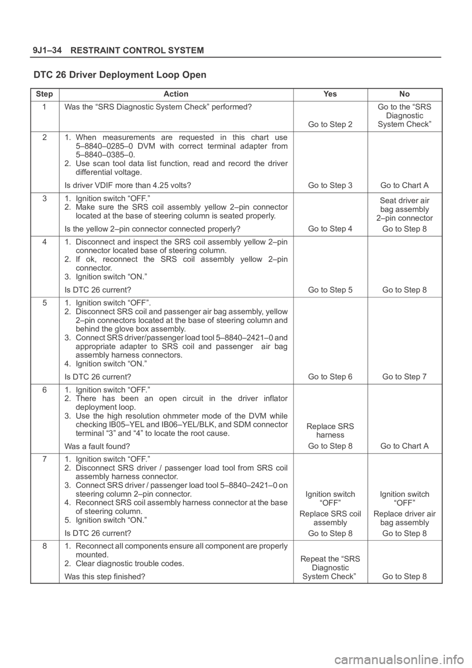
2. This test determines whether the malfunction is in
the SDM.
3. This test verifies proper connection of the yellow
2–pin connector at the base of the steering column.
4. This test checks for proper contact and/or corrosion
of the yellow 2–pin connector at the base of the
steering column.
5. This test isolates the malfunction to one side of the
SRS coil assembly yellow 2–pin connector located
at the base of steering column.
6. This test determines whether the open is in the
wiring.
7. This test determines whether the malfunction is in
the SRS coil assembly or the driver air bag
assembly.
Diagnostic Aids:
An intermittent condition is likely to be caused by a poor
connection at the driver air bag assembly harness 2–pin
connector terminals “1” and “2” at the top of the steering
column, SRS coil assembly harness 2–pin connection
terminals “1” and “2”, SDM terminals “3” and “4”, or an
open in IB05–YEL and IB06–YEL/BLK.
Page 3521 of 6000
RESTRAINT CONTROL SYSTEM 9J1–34
DTC 26 Driver Deployment Loop Open
StepActionYe sNo
1Was the “SRS Diagnostic System Check” performed?
Go to Step 2
Go to the “SRS
Diagnostic
System Check”
21. When measurements are requested in this chart use
5–8840–0285–0 DVM with correct terminal adapter from
5–8840–0385–0.
2. Use scan tool data list function, read and record the driver
differential voltage.
Is driver VDIF more than 4.25 volts?
Go to Step 3Go to Chart A
31. Ignition switch “OFF.”
2. Make sure the SRS coil assembly yellow 2–pin connector
located at the base of steering column is seated properly.
Is the yellow 2–pin connector connected properly?
Go to Step 4
Seat driver air
bag assembly
2–pin connector
Go to Step 8
41. Disconnect and inspect the SRS coil assembly yellow 2–pin
connector located base of steering column.
2. If ok, reconnect the SRS coil assembly yellow 2–pin
connector.
3. Ignition switch “ON.”
Is DTC 26 current?
Go to Step 5Go to Step 8
51. Ignition switch “OFF”.
2. Disconnect SRS coil and passenger air bag assembly, yellow
2–pin connectors located at the base of steering column and
behind the glove box assembly.
3. Connect SRS driver/passenger load tool 5–8840–2421–0 and
appropriate adapter to SRS coil and passenger air bag
assembly harness connectors.
4. Ignition switch “ON.”
Is DTC 26 current?
Go to Step 6Go to Step 7
61. Ignition switch “OFF.”
2. There has been an open circuit in the driver inflator
deployment loop.
3. Use the high resolution ohmmeter mode of the DVM while
checking IB05–YEL and IB06–YEL/BLK, and SDM connector
terminal “3” and “4” to locate the root cause.
Was a fault found?
Replace SRS
harness
Go to Step 8
Go to Chart A
71. Ignition switch “OFF.”
2. Disconnect SRS driver / passenger load tool from SRS coil
assembly harness connector.
3. Connect SRS driver / passenger load tool 5–8840–2421–0 on
steering column 2–pin connector.
4. Reconnect SRS coil assembly harness connector at the base
of steering column.
5. Ignition switch “ON.”
Is DTC 26 current?
Ignition switch
“OFF”
Replace SRS coil
assembly
Go to Step 8Ignition switch
“OFF”
Replace driver air
bag assembly
Go to Step 8
81. Reconnect all components ensure all component are properly
mounted.
2. Clear diagnostic trouble codes.
Was this step finished?
Repeat the “SRS
Diagnostic
System Check”
Go to Step 8
Page 3544 of 6000
9J1–57
RESTRAINT CONTROL SYSTEM
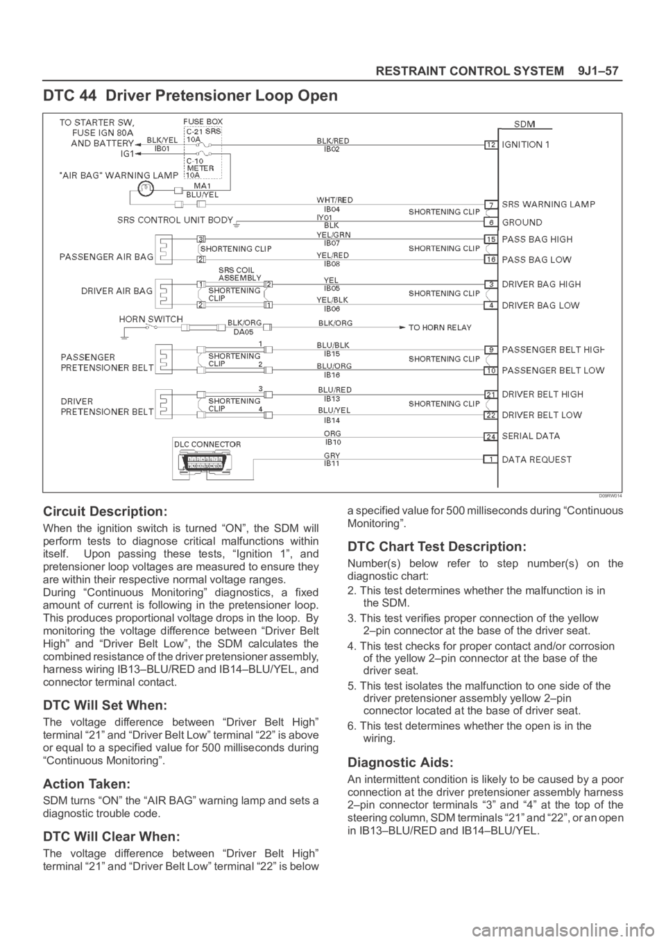
DTC 44 Driver Pretensioner Loop Open
D09RW014
Circuit Description:
When the ignition switch is turned “ON”, the SDM will
perform tests to diagnose critical malfunctions within
itself. Upon passing these tests, “Ignition 1”, and
pretensioner loop voltages are measured to ensure they
are within their respective normal voltage ranges.
During “Continuous Monitoring” diagnostics, a fixed
amount of current is following in the pretensioner loop.
This produces proportional voltage drops in the loop. By
monitoring the voltage difference between “Driver Belt
High” and “Driver Belt Low”, the SDM calculates the
combined resistance of the driver pretensioner assembly,
harness wiring IB13–BLU/RED and IB14–BLU/YEL, and
connector terminal contact.
DTC Will Set When:
The voltage difference between “Driver Belt High”
terminal “21” and “Driver Belt Low” terminal “22” is above
or equal to a specified value for 500 milliseconds during
“Continuous Monitoring”.
Action Taken:
SDM turns “ON” the “AIR BAG” warning lamp and sets a
diagnostic trouble code.
DTC Will Clear When:
The voltage difference between “Driver Belt High”
terminal “21” and “Driver Belt Low” terminal “22” is belowa specified value for 500 milliseconds during “Continuous
Monitoring”.
DTC Chart Test Description:
Number(s) below refer to step number(s) on the
diagnostic chart:
2. This test determines whether the malfunction is in
the SDM.
3. This test verifies proper connection of the yellow
2–pin connector at the base of the driver seat.
4. This test checks for proper contact and/or corrosion
of the yellow 2–pin connector at the base of the
driver seat.
5. This test isolates the malfunction to one side of the
driver pretensioner assembly yellow 2–pin
connector located at the base of driver seat.
6. This test determines whether the open is in the
wiring.
Diagnostic Aids:
An intermittent condition is likely to be caused by a poor
connection at the driver pretensioner assembly harness
2–pin connector terminals “3” and “4” at the top of the
steering column, SDM terminals “21” and “22”, or an open
in IB13–BLU/RED and IB14–BLU/YEL.
Page 3555 of 6000
10A–4
CRUISE CONTROL SYSTEM
Starter Switch
Removal
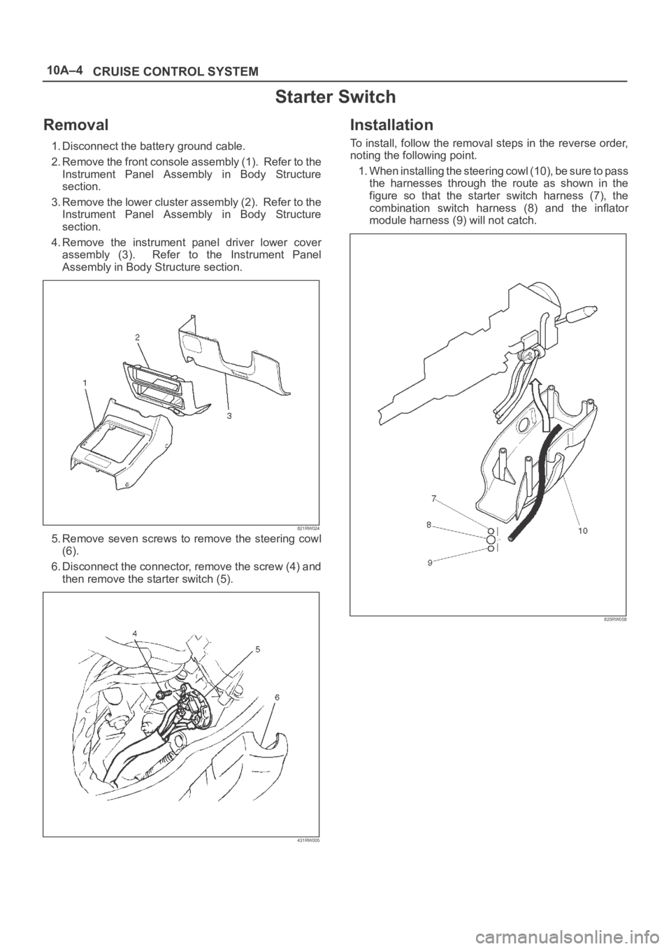
1. Disconnect the battery ground cable.
2. Remove the front console assembly (1). Refer to the
Instrument Panel Assembly in Body Structure
section.
3. Remove the lower cluster assembly (2). Refer to the
Instrument Panel Assembly in Body Structure
section.
4. Remove the instrument panel driver lower cover
assembly (3). Refer to the Instrument Panel
Assembly in Body Structure section.
821RW024
5. Remove seven screws to remove the steering cowl
(6).
6. Disconnect the connector, remove the screw (4) and
then remove the starter switch (5).
431RW005
Installation
To install, follow the removal steps in the reverse order,
noting the following point.
1. When installing the steering cowl (10), be sure to pass
the harnesses through the route as shown in the
figure so that the starter switch harness (7), the
combination switch harness (8) and the inflator
module harness (9) will not catch.
825RW058
Page 3942 of 6000
DIFFERENTIAL (FRONT) 4A1–2
Front Drive Axle
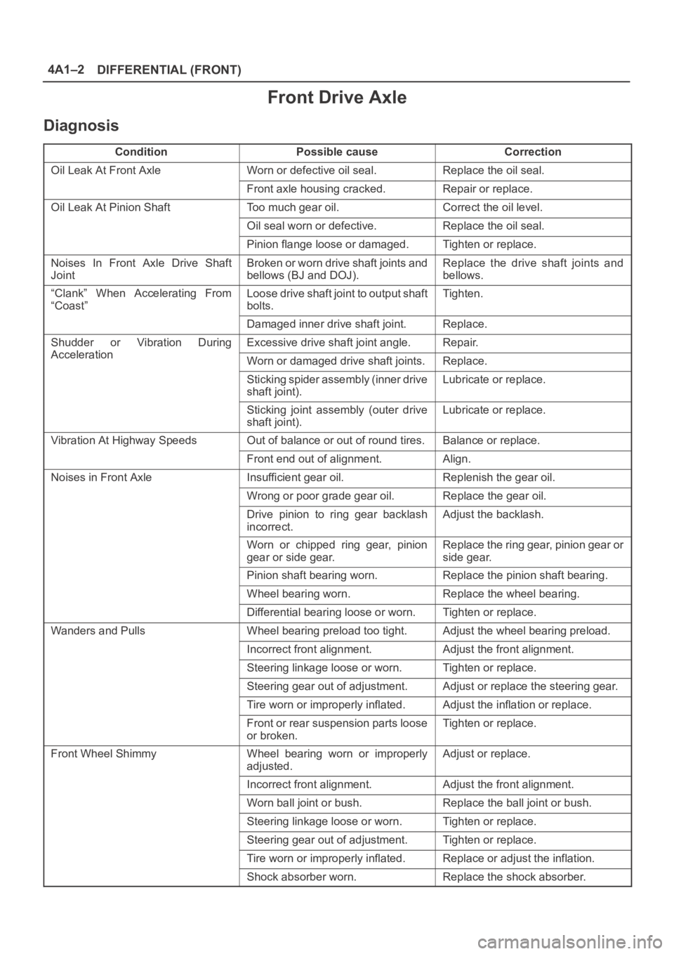
Diagnosis
ConditionPossible causeCorrection
Oil Leak At Front AxleWorn or defective oil seal.Replace the oil seal.
Front axle housing cracked.Repair or replace.
Oil Leak At Pinion ShaftToo much gear oil.Correct the oil level.
Oil seal worn or defective.Replace the oil seal.
Pinion flange loose or damaged.Tighten or replace.
Noises In Front Axle Drive Shaft
JointBroken or worn drive shaft joints and
bellows (BJ and DOJ).Replace the drive shaft joints and
bellows.
“Clank” When Accelerating From
“Coast”Loose drive shaft joint to output shaft
bolts.Tighten.
Damaged inner drive shaft joint.Replace.
Shudder or Vibration During
Acceleration
Excessive drive shaft joint angle.Repair.
AccelerationWorn or damaged drive shaft joints.Replace.
Sticking spider assembly (inner drive
shaft joint).Lubricate or replace.
Sticking joint assembly (outer drive
shaft joint).Lubricate or replace.
Vibration At Highway SpeedsOut of balance or out of round tires.Balance or replace.
Front end out of alignment.Align.
Noises in Front AxleInsufficient gear oil.Replenish the gear oil.
Wrong or poor grade gear oil.Replace the gear oil.
Drive pinion to ring gear backlash
incorrect.Adjust the backlash.
Worn or chipped ring gear, pinion
gear or side gear.Replace the ring gear, pinion gear or
side gear.
Pinion shaft bearing worn.Replace the pinion shaft bearing.
Wheel bearing worn.Replace the wheel bearing.
Differential bearing loose or worn.Tighten or replace.
Wanders and PullsWheel bearing preload too tight.Adjust the wheel bearing preload.
Incorrect front alignment.Adjust the front alignment.
Steering linkage loose or worn.Tighten or replace.
Steering gear out of adjustment.Adjust or replace the steering gear.
Tire worn or improperly inflated.Adjust the inflation or replace.
Front or rear suspension parts loose
or broken.Tighten or replace.
Front Wheel ShimmyWheel bearing worn or improperly
adjusted.Adjust or replace.
Incorrect front alignment.Adjust the front alignment.
Worn ball joint or bush.Replace the ball joint or bush.
Steering linkage loose or worn.Tighten or replace.
Steering gear out of adjustment.Tighten or replace.
Tire worn or improperly inflated.Replace or adjust the inflation.
Shock absorber worn.Replace the shock absorber.
Page 3946 of 6000
DIFFERENTIAL (FRONT) 4A1–6
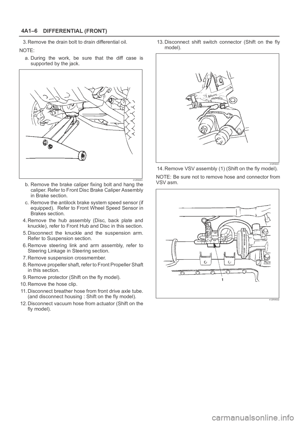
3. Remove the drain bolt to drain differential oil.
NOTE:
a. During the work, be sure that the diff case is
supported by the jack.
412RS003
b. Remove the brake caliper fixing bolt and hang the
caliper. Refer to Front Disc Brake Caliper Assembly
in Brake section.
c. Remove the antilock brake system speed sensor (if
equipped). Refer to Front Wheel Speed Sensor in
Brakes section.
4. Remove the hub assembly (Disc, back plate and
knuckle), refer to Front Hub and Disc in this section.
5. Disconnect the knuckle and the suspension arm.
Refer to Suspension section.
6. Remove steering link and arm assembly, refer to
Steering Linkage in Steering section.
7. Remove suspension crossmember.
8. Remove propeller shaft, refer to Front Propeller Shaft
in this section.
9. Remove protector (Shift on the fly model).
10. Remove the hose clip.
11. Disconnect breather hose from front drive axle tube.
(and disconnect housing : Shift on the fly model).
12. Disconnect vacuum hose from actuator (Shift on the
fly model).13. Disconnect shift switch connector (Shift on the fly
model).
412RS031
14. Remove VSV assembly (1) (Shift on the fly model).
NOTE: Be sure not to remove hose and connector from
VSV asm.
412RW002