1998 OPEL FRONTERA OBD port
[x] Cancel search: OBD portPage 1292 of 6000
6E–175 ENGINE DRIVEABILITY AND EMISSIONS
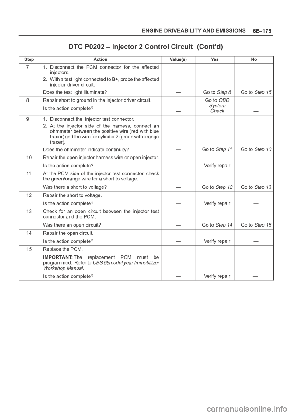
DTC P0202 – Injector 2 Control Circuit
StepNo Ye s Va l u e ( s ) Action
71. Disconnect the PCM connector for the affected
injectors.
2. With a test light connected to B+, probe the affected
injector driver circuit.
Does the test light illuminate?
—Go to Step 8Go to Step 15
8Repair short to ground in the injector driver circuit.
Is the action complete?
—
Go to OBD
System
Check
—
91. Disconnect the injector test connector.
2. At the injector side of the harness, connect an
ohmmeter between the positive wire (red with blue
tracer) and the wire for cylinder 2 (green with orange
tracer).
Does the ohmmeter indicate continuity?
—Go to Step 11Go to Step 10
10Repair the open injector harness wire or open injector.
Is the action complete?
—Verify repair—
11At the PCM side of the injector test connector, check
the green/orange wire for a short to voltage.
Was there a short to voltage?
—Go to Step 12Go to Step 13
12Repair the short to voltage.
Is the action complete?
—Verify repair—
13Check for an open circuit between the injector test
connector and the PCM.
Was there an open circuit?
—Go to Step 14Go to Step 15
14Repair the open circuit.
Is the action complete?
—Verify repair—
15Replace the PCM.
IMPORTANT:The replacement PCM must be
programmed. Refer to
UBS 98model year Immobilizer
Workshop Manual.
Is the action complete?—Verify repair—
Page 1295 of 6000
6E–178
ENGINE DRIVEABILITY AND EMISSIONS
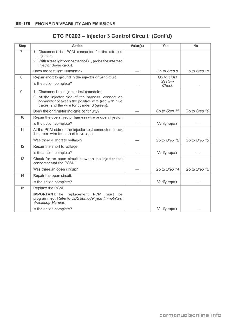
DTC P0203 – Injector 3 Control Circuit
StepNo Ye s Va l u e ( s ) Action
71. Disconnect the PCM connector for the affected
injectors.
2. With a test light connected to B+, probe the affected
injector driver circuit.
Does the test light illuminate?
—Go to Step 8Go to Step 15
8Repair short to ground in the injector driver circuit.
Is the action complete?
—
Go to OBD
System
Check
—
91. Disconnect the injector test connector.
2. At the injector side of the harness, connect an
ohmmeter between the positive wire (red with blue
tracer) and the wire for cylinder 3 (green).
Does the ohmmeter indicate continuity?
—Go to Step 11Go to Step 10
10Repair the open injector harness wire or open injector.
Is the action complete?
—Verify repair—
11At the PCM side of the injector test connector, check
the green wire for a short to voltage.
Was there a short to voltage?
—Go to Step 12Go to Step 13
12Repair the short to voltage.
Is the action complete?
—Verify repair—
13Check for an open circuit between the injector test
connector and the PCM.
Was there an open circuit?
—Go to Step 14Go to Step 15
14Repair the open circuit.
Is the action complete?
—Verify repair—
15Replace the PCM.
IMPORTANT:The replacement PCM must be
programmed. Refer to
UBS 98model year Immobilizer
Workshop Manual.
Is the action complete?—Verify repair—
Page 1298 of 6000
6E–181 ENGINE DRIVEABILITY AND EMISSIONS
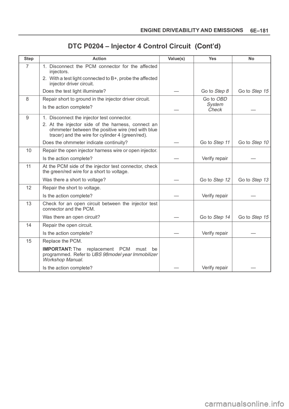
DTC P0204 – Injector 4 Control Circuit
StepNo Ye s Va l u e ( s ) Action
71. Disconnect the PCM connector for the affected
injectors.
2. With a test light connected to B+, probe the affected
injector driver circuit.
Does the test light illuminate?
—Go to Step 8Go to Step 15
8Repair short to ground in the injector driver circuit.
Is the action complete?
—
Go to OBD
System
Check
—
91. Disconnect the injector test connector.
2. At the injector side of the harness, connect an
ohmmeter between the positive wire (red with blue
tracer) and the wire for cylinder 4 (green/red).
Does the ohmmeter indicate continuity?
—Go to Step 11Go to Step 10
10Repair the open injector harness wire or open injector.
Is the action complete?
—Verify repair—
11At the PCM side of the injector test connector, check
the green/red wire for a short to voltage.
Was there a short to voltage?
—Go to Step 12Go to Step 13
12Repair the short to voltage.
Is the action complete?
—Verify repair—
13Check for an open circuit between the injector test
connector and the PCM.
Was there an open circuit?
—Go to Step 14Go to Step 15
14Repair the open circuit.
Is the action complete?
—Verify repair—
15Replace the PCM.
IMPORTANT:The replacement PCM must be
programmed. Refer to
UBS 98model year Immobilizer
Workshop Manual.
Is the action complete?—Verify repair—
Page 1301 of 6000
6E–184
ENGINE DRIVEABILITY AND EMISSIONS
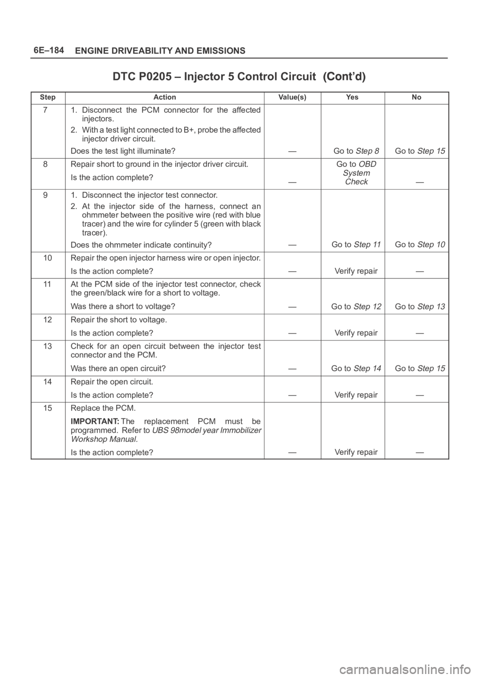
DTC P0205 – Injector 5 Control Circuit
StepNo Ye s Va l u e ( s ) Action
71. Disconnect the PCM connector for the affected
injectors.
2. With a test light connected to B+, probe the affected
injector driver circuit.
Does the test light illuminate?
—Go to Step 8Go to Step 15
8Repair short to ground in the injector driver circuit.
Is the action complete?
—
Go to OBD
System
Check
—
91. Disconnect the injector test connector.
2. At the injector side of the harness, connect an
ohmmeter between the positive wire (red with blue
tracer) and the wire for cylinder 5 (green with black
tracer).
Does the ohmmeter indicate continuity?
—Go to Step 11Go to Step 10
10Repair the open injector harness wire or open injector.
Is the action complete?
—Verify repair—
11At the PCM side of the injector test connector, check
the green/black wire for a short to voltage.
Was there a short to voltage?
—Go to Step 12Go to Step 13
12Repair the short to voltage.
Is the action complete?
—Verify repair—
13Check for an open circuit between the injector test
connector and the PCM.
Was there an open circuit?
—Go to Step 14Go to Step 15
14Repair the open circuit.
Is the action complete?
—Verify repair—
15Replace the PCM.
IMPORTANT:The replacement PCM must be
programmed. Refer to
UBS 98model year Immobilizer
Workshop Manual.
Is the action complete?—Verify repair—
Page 1304 of 6000
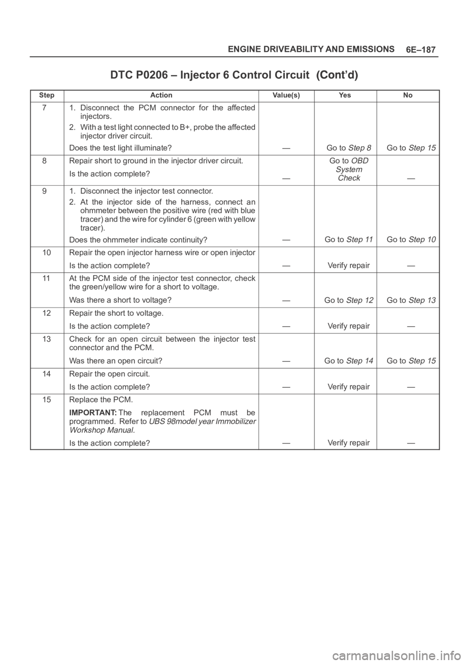
6E–187 ENGINE DRIVEABILITY AND EMISSIONS
DTC P0206 – Injector 6 Control Circuit
StepNo Ye s Va l u e ( s ) Action
71. Disconnect the PCM connector for the affected
injectors.
2. With a test light connected to B+, probe the affected
injector driver circuit.
Does the test light illuminate?
—Go to Step 8Go to Step 15
8Repair short to ground in the injector driver circuit.
Is the action complete?
—
Go to OBD
System
Check
—
91. Disconnect the injector test connector.
2. At the injector side of the harness, connect an
ohmmeter between the positive wire (red with blue
tracer) and the wire for cylinder 6 (green with yellow
tracer).
Does the ohmmeter indicate continuity?
—Go to Step 11Go to Step 10
10Repair the open injector harness wire or open injector
Is the action complete?
—Verify repair—
11At the PCM side of the injector test connector, check
the green/yellow wire for a short to voltage.
Was there a short to voltage?
—Go to Step 12Go to Step 13
12Repair the short to voltage.
Is the action complete?
—Verify repair—
13Check for an open circuit between the injector test
connector and the PCM.
Was there an open circuit?
—Go to Step 14Go to Step 15
14Repair the open circuit.
Is the action complete?
—Verify repair—
15Replace the PCM.
IMPORTANT:The replacement PCM must be
programmed. Refer to
UBS 98model year Immobilizer
Workshop Manual.
Is the action complete?—Verify repair—
Page 1306 of 6000

6E–189 ENGINE DRIVEABILITY AND EMISSIONS
DTC P0325 – KS Module Circuit
StepActionVa l u e ( s )Ye sNo
1Was the “On-Board Diagnostic (OBD) System Check”
performed?
—Go to Step 2
Go to OBD
System
Check
2IMPORTANT:If an engine knock can be heard, repair
the engine mechanical problem before proceeding with
this diagnostic.
1. Operate the vehicle within parameters specified
under criteria included in “Conditions for Setting the
DTC.”
2. Using Tech 2, monitor “Specific DTC” info for DTC
P0325 until the DTC P0325 test runs.
3. Note the test result.
Does Tech 2 indicate DTC P0325 failed this ignition?
—Go to Step 4Go to Step 3
31. Ignition “ON,” engine “OFF.”
2. Review and record Tech 2 Failure Records data for
DTC P0325.
3. Operate the vehicle within Failure Records
conditions.
4. Using Tech 2, monitor “Specific DTC” info for DTC
P0325 until the DTC P0325 test runs.
Does Tech 2 indicate DTC P0325 test failed this
ignition?
—Go to Step 4
Refer to
Diagnostic
Aids
4Replace the PCM.
IMPORTANT:The replacement PCM must be
programmed. Refer to
UBS 98model year Immobilizer
Workshop Manual.
Is the action complete?—Verify repair—
Page 1308 of 6000
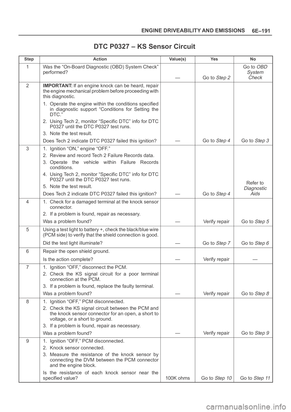
6E–191 ENGINE DRIVEABILITY AND EMISSIONS
DTC P0327 – KS Sensor Circuit
StepActionVa l u e ( s )Ye sNo
1Was the “On-Board Diagnostic (OBD) System Check”
performed?
—Go to Step 2
Go to OBD
System
Check
2IMPORTANT:If an engine knock can be heard, repair
the engine mechanical problem before proceeding with
this diagnostic.
1. Operate the engine within the conditions specified
in diagnostic support “Conditions for Setting the
DTC.”
2. Using Tech 2, monitor “Specific DTC” info for DTC
P0327 until the DTC P0327 test runs.
3. Note the test result.
Does Tech 2 indicate DTC P0327 failed this ignition?
—Go to Step 4Go to Step 3
31. Ignition “ON,” engine “OFF.”
2. Review and record Tech 2 Failure Records data.
3. Operate the vehicle within Failure Records
conditions.
4. Using Tech 2, monitor “Specific DTC” info for DTC
P0327 until the DTC P0327 test runs.
5. Note the test result.
Does Tech 2 indicate DTC P0327 failed this ignition?
—Go to Step 4
Refer to
Diagnostic
Aids
41. Check for a damaged terminal at the knock sensor
connector.
2. If a problem is found, repair as necessary.
Was a problem found?
—Verify repairGo to Step 5
5Using a test light to battery +, check the black/blue wire
(PCM side) to verify that the shield connection is good.
Did the test light illuminate?
—Go to Step 7Go to Step 6
6Repair the open shield ground.
Is the action complete?
—Verify repair—
71. Ignition “OFF,” disconnect the PCM.
2. Check the KS signal circuit for a poor terminal
connection at the PCM.
3. If a problem is found, replace the faulty terminal.
Was a problem found?
—Verify repairGo to Step 8
81. Ignition “OFF,” PCM disconnected.
2. Check the KS signal circuit between the PCM and
the knock sensor connector for an open, a short to
voltage, or a short to ground.
3. If a problem is found, repair as necessary.
Was a problem found?
—Verify repairGo to Step 9
91. Ignition “OFF,” PCM disconnected.
2. Knock sensor connected.
3. Measure the resistance of the knock sensor by
connecting the DVM between the PCM connector
and the engine block.
Is the resistance of each knock sensor near the
specified value?
100K ohmsGo to Step 10Go to Step 11
Page 1311 of 6000
6E–194
ENGINE DRIVEABILITY AND EMISSIONS
Damaged harness – Inspect the wiring harness for
damage. If the harness appears to be OK, disconnect
the PCM, turn the ignition on and observe a voltmeter
connected to the 58X reference circuit at the PCM
harness connector while moving connectors and
wiring harnesses related to the ICM. A change in
voltage will indicate the location of the fault.Reviewing the Failure Records vehicle mileage since the
diagnostic test last failed may help determine how often
the condition that caused the DTC to be set occurs. This
may assist in diagnosing the condition.
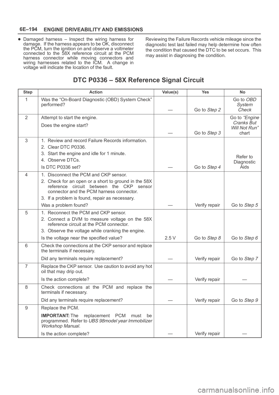
DTC P0336 – 58X Reference Signal Circuit
StepActionVa l u e ( s )Ye sNo
1Was the “On-Board Diagnostic (OBD) System Check”
performed?
—Go to Step 2
Go to OBD
System
Check
2Attempt to start the engine.
Does the engine start?
—Go to Step 3
Go to “Engine
Cranks But
Will Not Run”
chart
31. Review and record Failure Records information.
2. Clear DTC P0336.
3. Start the engine and idle for 1 minute.
4. Observe DTCs.
Is DTC P0336 set?
—Go to Step 4
Refer to
Diagnostic
Aids
41. Disconnect the PCM and CKP sensor.
2. Check for an open or a short to ground in the 58X
reference circuit between the CKP sensor
connector and the PCM harness connector.
3. If a problem is found, repair as necessary.
Was a problem found?
—Verify repairGo to Step 5
51. Reconnect the PCM and CKP sensor.
2. Connect a DVM to measure voltage on the 58X
reference circuit at the PCM connector.
3. Observe the voltage while cranking the engine.
Is the voltage near the specified value?
2.5 VGo to Step 8Go to Step 6
6Check the connections at the CKP sensor and replace
the terminals if necessary.
Did any terminals require replacement?
—Verify repairGo to Step 7
7Replace the CKP sensor. Use caution to avoid any hot
oil that may drip out.
Is the action complete?
—Verify repair—
8Check connections at the PCM and replace the
terminals if necessary.
Did any terminals require replacement?
—Verify repairGo to Step 9
9Replace the PCM.
IMPORTANT:The replacement PCM must be
programmed. Refer to
UBS 98model year Immobilizer
Workshop Manual.
Is the action complete?—Verify repair—