1998 OPEL FRONTERA OBD port
[x] Cancel search: OBD portPage 1167 of 6000
6E–50
ENGINE DRIVEABILITY AND EMISSIONS
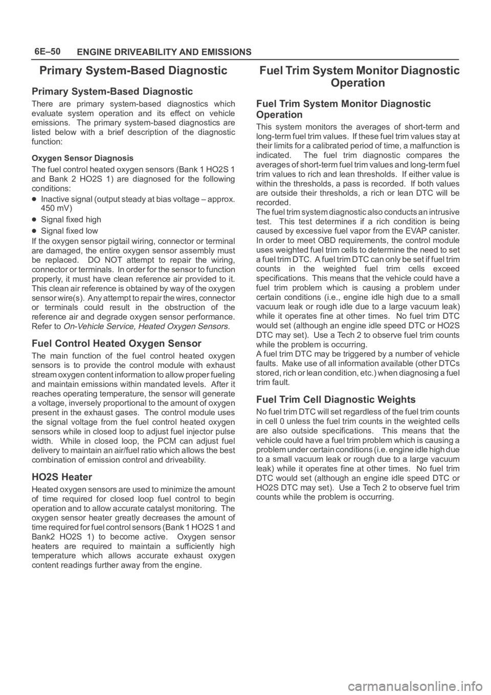
Primary System-Based Diagnostic
Primary System-Based Diagnostic
There are primary system-based diagnostics which
evaluate system operation and its effect on vehicle
emissions. The primary system-based diagnostics are
listed below with a brief description of the diagnostic
function:
Oxygen Sensor Diagnosis
The fuel control heated oxygen sensors (Bank 1 HO2S 1
and Bank 2 HO2S 1) are diagnosed for the following
conditions:
Inactive signal (output steady at bias voltage – approx.
450 mV)
Signal fixed high
Signal fixed low
If the oxygen sensor pigtail wiring, connector or terminal
are damaged, the entire oxygen sensor assembly must
be replaced. DO NOT attempt to repair the wiring,
connector or terminals. In order for the sensor to function
properly, it must have clean reference air provided to it.
This clean air reference is obtained by way of the oxygen
sensor wire(s). Any attempt to repair the wires, connector
or terminals could result in the obstruction of the
reference air and degrade oxygen sensor performance.
Refer to
On-Vehicle Service, Heated Oxygen Sensors.
Fuel Control Heated Oxygen Sensor
The main function of the fuel control heated oxygen
sensors is to provide the control module with exhaust
stream oxygen content information to allow proper fueling
and maintain emissions within mandated levels. After it
reaches operating temperature, the sensor will generate
a voltage, inversely proportional to the amount of oxygen
present in the exhaust gases. The control module uses
the signal voltage from the fuel control heated oxygen
sensors while in closed loop to adjust fuel injector pulse
width. While in closed loop, the PCM can adjust fuel
delivery to maintain an air/fuel ratio which allows the best
combination of emission control and driveability.
HO2S Heater
Heated oxygen sensors are used to minimize the amount
of time required for closed loop fuel control to begin
operation and to allow accurate catalyst monitoring. The
oxygen sensor heater greatly decreases the amount of
time required for fuel control sensors (Bank 1 HO2S 1 and
Bank2 HO2S 1) to become active. Oxygen sensor
heaters are required to maintain a sufficiently high
temperature which allows accurate exhaust oxygen
content readings further away from the engine.
Fuel Trim System Monitor Diagnostic
Operation
Fuel Trim System Monitor Diagnostic
Operation
This system monitors the averages of short-term and
long-term fuel trim values. If these fuel trim values stay at
their limits for a calibrated period of time, a malfunction is
indicated. The fuel trim diagnostic compares the
averages of short-term fuel trim values and long-term fuel
trim values to rich and lean thresholds. If either value is
within the thresholds, a pass is recorded. If both values
are outside their thresholds, a rich or lean DTC will be
recorded.
The fuel trim system diagnostic also conducts an intrusive
test. This test determines if a rich condition is being
caused by excessive fuel vapor from the EVAP canister.
In order to meet OBD requirements, the control module
uses weighted fuel trim cells to determine the need to set
a fuel trim DTC. A fuel trim DTC can only be set if fuel trim
counts in the weighted fuel trim cells exceed
specifications. This means that the vehicle could have a
fuel trim problem which is causing a problem under
certain conditions (i.e., engine idle high due to a small
vacuum leak or rough idle due to a large vacuum leak)
while it operates fine at other times. No fuel trim DTC
would set (although an engine idle speed DTC or HO2S
DTC may set). Use a Tech 2 to observe fuel trim counts
while the problem is occurring.
A fuel trim DTC may be triggered by a number of vehicle
faults. Make use of all information available (other DTCs
stored, rich or lean condition, etc.) when diagnosing a fuel
trim fault.
Fuel Trim Cell Diagnostic Weights
N o f u e l t r i m D T C w i l l s e t r e g a r d l e s s o f t h e f u e l t r i m c o u n t s
in cell 0 unless the fuel trim counts in the weighted cells
are also outside specifications. This means that the
vehicle could have a fuel trim problem which is causing a
problem under certain conditions (i.e. engine idle high due
to a small vacuum leak or rough due to a large vacuum
leak) while it operates fine at other times. No fuel trim
DTC would set (although an engine idle speed DTC or
HO2S DTC may set). Use a Tech 2 to observe fuel trim
counts while the problem is occurring.
Page 1170 of 6000
6E–53 ENGINE DRIVEABILITY AND EMISSIONS
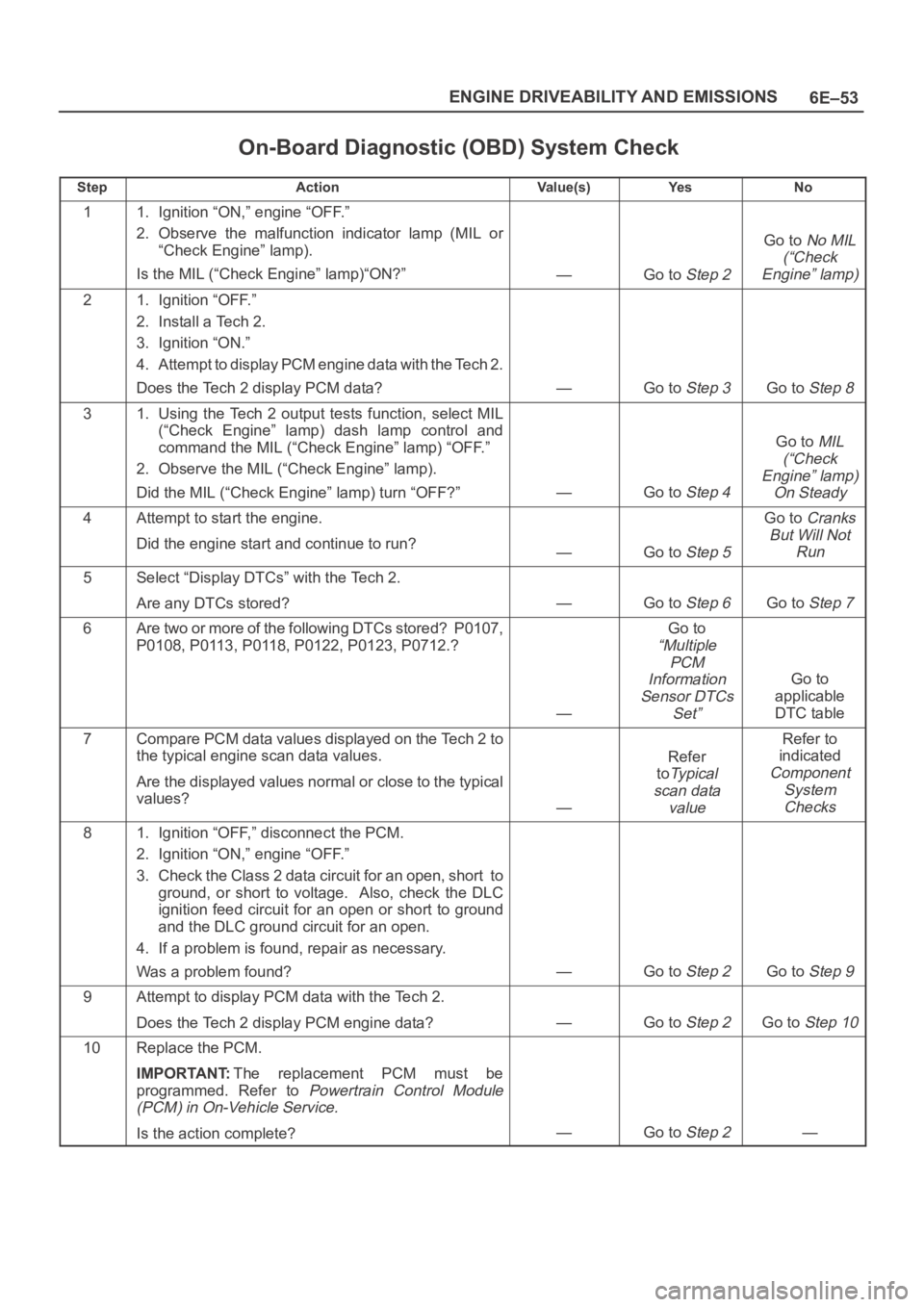
On-Board Diagnostic (OBD) System Check
StepActionVa l u e ( s )Ye sNo
11. Ignition “ON,” engine “OFF.”
2. Observe the malfunction indicator lamp (MIL or
“Check Engine” lamp).
Is the MIL (“Check Engine” lamp)“ON?”
—Go to Step 2
Go to No MIL
(“Check
Engine” lamp)
21. Ignition “OFF.”
2. Install a Tech 2.
3. Ignition “ON.”
4. Attempt to display PCM engine data with the Tech 2.
Does the Tech 2 display PCM data?
—Go to Step 3Go to Step 8
31. Using the Tech 2 output tests function, select MIL
(“Check Engine” lamp) dash lamp control and
command the MIL (“Check Engine” lamp) “OFF.”
2. Observe the MIL (“Check Engine” lamp).
Did the MIL (“Check Engine” lamp) turn “OFF?”
—Go to Step 4
Go to MIL
(“Check
Engine” lamp)
On Steady
4Attempt to start the engine.
Did the engine start and continue to run?
—Go to Step 5
Go to Cranks
But Will Not
Run
5Select “Display DTCs” with the Tech 2.
Are any DTCs stored?
—Go to Step 6Go to Step 7
6Are two or more of the following DTCs stored? P0107,
P0108, P0113, P0118, P0122, P0123, P0712.?
—
Go to
“Multiple
PCM
Information
Sensor DTCs
Set”
Go to
applicable
DTC table
7Compare PCM data values displayed on the Tech 2 to
the typical engine scan data values.
Are the displayed values normal or close to the typical
values?
—
Refer
to
Ty p i c a l
scan data
value
Refer to
indicated
Component
System
Checks
81. Ignition “OFF,” disconnect the PCM.
2. Ignition “ON,” engine “OFF.”
3. Check the Class 2 data circuit for an open, short to
ground, or short to voltage. Also, check the DLC
ignition feed circuit for an open or short to ground
and the DLC ground circuit for an open.
4. If a problem is found, repair as necessary.
Was a problem found?
—Go to Step 2Go to Step 9
9Attempt to display PCM data with the Tech 2.
Does the Tech 2 display PCM engine data?
—Go to Step 2Go to Step 10
10Replace the PCM.
IMPORTANT:The replacement PCM must be
programmed. Refer to
Powertrain Control Module
(PCM) in On-Vehicle Service.
Is the action complete?—Go to Step 2—
Page 1172 of 6000
6E–55 ENGINE DRIVEABILITY AND EMISSIONS
Damaged harness–Inspect the wiring harness for
damage. If the harness appears to OK, observe the
A/C clutch while moving connectors and wiring
harnesses related to the A/C. A sudden clutch
malfunction will indicate the source of the intermittent
fault.
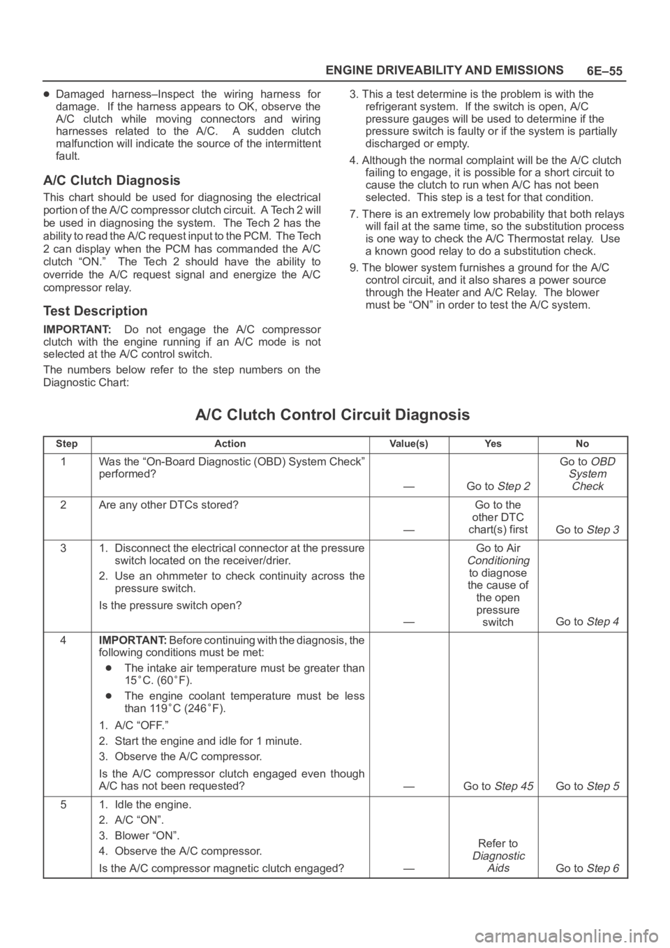
A/C Clutch Diagnosis
This chart should be used for diagnosing the electrical
p o r t i o n o f t h e A / C c o m p r e s s o r c l u t c h c i r c u i t . A Te c h 2 w i l l
be used in diagnosing the system. The Tech 2 has the
ability to read the A/C request input to the PCM. The Tech
2 can display when the PCM has commanded the A/C
clutch “ON.” The Tech 2 should have the ability to
override the A/C request signal and energize the A/C
compressor relay.
Test Description
IMPORTANT:Do not engage the A/C compressor
clutch with the engine running if an A/C mode is not
selected at the A/C control switch.
The numbers below refer to the step numbers on the
Diagnostic Chart:3. This a test determine is the problem is with the
refrigerant system. If the switch is open, A/C
pressure gauges will be used to determine if the
pressure switch is faulty or if the system is partially
discharged or empty.
4. Although the normal complaint will be the A/C clutch
failing to engage, it is possible for a short circuit to
cause the clutch to run when A/C has not been
selected. This step is a test for that condition.
7. There is an extremely low probability that both relays
will fail at the same time, so the substitution process
is one way to check the A/C Thermostat relay. Use
a known good relay to do a substitution check.
9. The blower system furnishes a ground for the A/C
control circuit, and it also shares a power source
through the Heater and A/C Relay. The blower
must be “ON” in order to test the A/C system.
A/C Clutch Control Circuit Diagnosis
StepActionVa l u e ( s )Ye sNo
1Was the “On-Board Diagnostic (OBD) System Check”
performed?
—Go to Step 2
Go to OBD
System
Check
2Are any other DTCs stored?
—
Go to the
other DTC
chart(s) first
Go to Step 3
31. Disconnect the electrical connector at the pressure
switch located on the receiver/drier.
2. Use an ohmmeter to check continuity across the
pressure switch.
Is the pressure switch open?
—
Go to Air
Conditioning
to diagnose
the cause of
the open
pressure
switch
Go to Step 4
4IMPORTANT:Before continuing with the diagnosis, the
following conditions must be met:
The intake air temperature must be greater than
15
C. (60F).
The engine coolant temperature must be less
than 119
C (246F).
1. A/C “OFF.”
2. Start the engine and idle for 1 minute.
3. Observe the A/C compressor.
Is the A/C compressor clutch engaged even though
A/C has not been requested?
—Go to Step 45Go to Step 5
51. Idle the engine.
2. A/C “ON”.
3. Blower “ON”.
4. Observe the A/C compressor.
Is the A/C compressor magnetic clutch engaged?
—
Refer to
Diagnostic
Aids
Go to Step 6
Page 1179 of 6000
6E–62
ENGINE DRIVEABILITY AND EMISSIONS
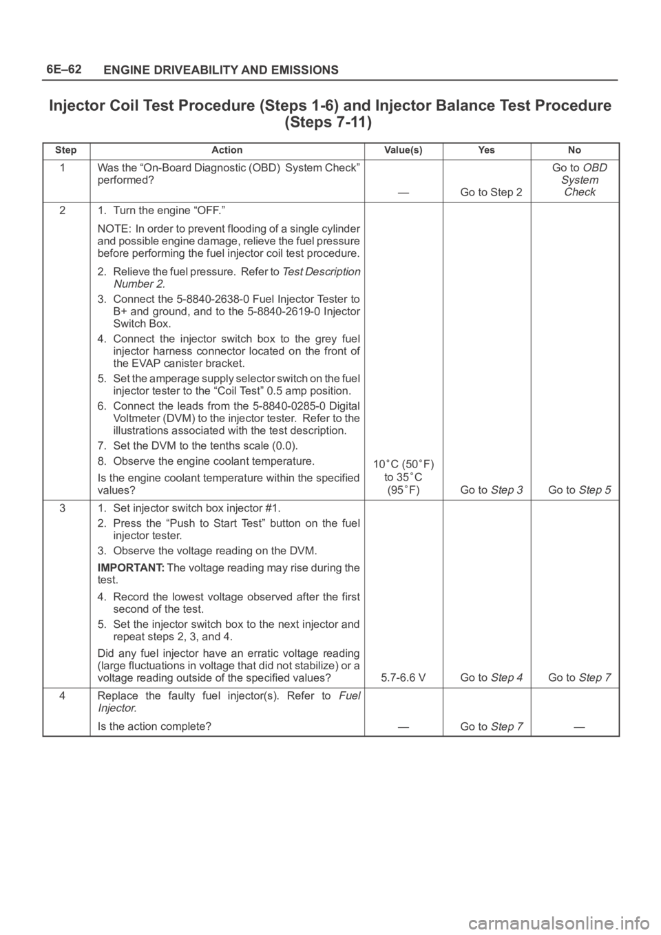
Injector Coil Test Procedure (Steps 1-6) and Injector Balance Test Procedure
(Steps 7-11)
StepActionVa l u e ( s )Ye sNo
1Was the “On-Board Diagnostic (OBD) System Check”
performed?
—Go to Step 2
Go to OBD
System
Check
21. Turn the engine “OFF.”
NOTE: In order to prevent flooding of a single cylinder
and possible engine damage, relieve the fuel pressure
before performing the fuel injector coil test procedure.
2. Relieve the fuel pressure. Refer to
Test Description
Number 2.
3. Connect the 5-8840-2638-0 Fuel Injector Tester to
B+ and ground, and to the 5-8840-2619-0 Injector
Switch Box.
4. Connect the injector switch box to the grey fuel
injector harness connector located on the front of
the EVAP canister bracket.
5. Set the amperage supply selector switch on the fuel
injector tester to the “Coil Test” 0.5 amp position.
6. Connect the leads from the 5-8840-0285-0 Digital
Voltmeter (DVM) to the injector tester. Refer to the
illustrations associated with the test description.
7. Set the DVM to the tenths scale (0.0).
8. Observe the engine coolant temperature.
Is the engine coolant temperature within the specified
values?
10C (50F)
to 35
C
(95
F)Go to Step 3Go to Step 5
31. Set injector switch box injector #1.
2. Press the “Push to Start Test” button on the fuel
injector tester.
3. Observe the voltage reading on the DVM.
IMPORTANT:The voltage reading may rise during the
test.
4. Record the lowest voltage observed after the first
second of the test.
5. Set the injector switch box to the next injector and
repeat steps 2, 3, and 4.
Did any fuel injector have an erratic voltage reading
(large fluctuations in voltage that did not stabilize) or a
voltage reading outside of the specified values?
5.7-6.6 VGo to Step 4Go to Step 7
4Replace the faulty fuel injector(s). Refer to Fuel
Injector.
Is the action complete?—Go to Step 7—
Page 1181 of 6000
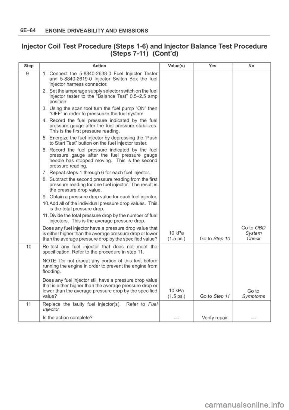
6E–64
ENGINE DRIVEABILITY AND EMISSIONS
Injector Coil Test Procedure (Steps 1-6) and Injector Balance Test Procedure
(Steps 7-11)
StepNo Ye s Va l u e ( s ) Action
91. Connect the 5-8840-2638-0 Fuel Injector Tester
and 5-8840-2619-0 Injector Switch Box the fuel
injector harness connector.
2. Set the amperage supply selector switch on the fuel
injector tester to the “Balance Test” 0.5–2.5 amp
position.
3. Using the scan tool turn the fuel pump “ON” then
“OFF” in order to pressurize the fuel system.
4. Record the fuel pressure indicated by the fuel
pressure gauge after the fuel pressure stabilizes.
This is the first pressure reading.
5. Energize the fuel injector by depressing the “Push
to Start Test” button on the fuel injector tester.
6. Record the fuel pressure indicated by the fuel
pressure gauge after the fuel pressure gauge
needle has stopped moving. This is the second
pressure reading.
7. Repeat steps 1 through 6 for each fuel injector.
8. Subtract the second pressure reading from the first
pressure reading for one fuel injector. The result is
the pressure drop value.
9. Obtain a pressure drop value for each fuel injector.
10.Add all of the individual pressure drop values. This
is the total pressure drop.
11. Divide the total pressure drop by the number of fuel
injectors. This is the average pressure drop.
Does any fuel injector have a pressure drop value that
is either higher than the average pressure drop or lower
than the average pressure drop by the specified value?
10 kPa
(1.5 psi)
Go to Step 10
Go to OBD
System
Check
10Re-test any fuel injector that does not meet the
specification. Refer to the procedure in step 11.
NOTE: Do not repeat any portion of this test before
running the engine in order to prevent the engine from
flooding.
Does any fuel injector still have a pressure drop value
that is either higher than the average pressure drop or
lower than the average pressure drop by the specified
value?
10 kPa
(1.5 psi)
Go to Step 11
Go to
Symptoms
11Replace the faulty fuel injector(s). Refer to Fuel
Injector.
Is the action complete?—Verify repair—
Page 1184 of 6000
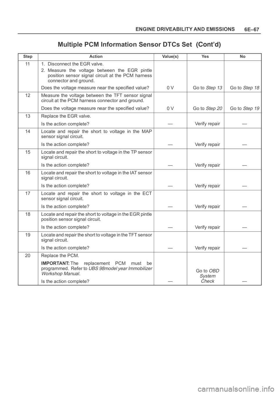
6E–67 ENGINE DRIVEABILITY AND EMISSIONS
Multiple PCM Information Sensor DTCs Set
StepNo Ye s Va l u e ( s ) Action
111. Disconnect the EGR valve.
2. Measure the voltage between the EGR pintle
position sensor signal circuit at the PCM harness
connector and ground.
Does the voltage measure near the specified value?
0 VGo to Step 13Go to Step 18
12Measure the voltage between the TFT sensor signal
circuit at the PCM harness connector and ground.
Does the voltage measure near the specified value?
0 VGo to Step 20Go to Step 19
13Replace the EGR valve.
Is the action complete?
—Verify repair—
14Locate and repair the short to voltage in the MAP
sensor signal circuit.
Is the action complete?
—Verify repair—
15Locate and repair the short to voltage in the TP sensor
signal circuit.
Is the action complete?
—Verify repair—
16Locate and repair the short to voltage in the IAT sensor
signal circuit.
Is the action complete?
—Verify repair—
17Locate and repair the short to voltage in the ECT
sensor signal circuit.
Is the action complete?
—Verify repair—
18Locate and repair the short to voltage in the EGR pintle
position sensor signal circuit.
Is the action complete?
—Verify repair—
19Locate and repair the short to voltage in the TFT sensor
signal circuit.
Is the action complete?
—Verify repair—
20Replace the PCM.
IMPORTANT:The replacement PCM must be
programmed. Refer to
UBS 98model year Immobilizer
Workshop Manual.
Is the action complete?—
Go to OBD
System
Check
—
Page 1195 of 6000
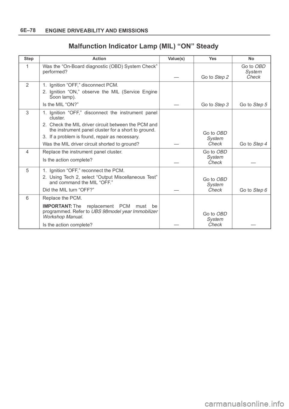
6E–78
ENGINE DRIVEABILITY AND EMISSIONS
Malfunction Indicator Lamp (MIL) “ON” Steady
StepActionVa l u e ( s )Ye sNo
1Was the “On-Board diagnostic (OBD) System Check”
performed?
—Go to Step 2
Go to OBD
System
Check
21. Ignition “OFF,” disconnect PCM.
2. Ignition “ON,” observe the MIL (Service Engine
Soon lamp).
Is the MIL “ON?”
—Go to Step 3Go to Step 5
31. Ignition “OFF,” disconnect the instrument panel
cluster.
2. Check the MIL driver circuit between the PCM and
the instrument panel cluster for a short to ground.
3. If a problem is found, repair as necessary.
Was the MIL driver circuit shorted to ground?
—
Go to OBD
System
Check
Go to Step 4
4Replace the instrument panel cluster.
Is the action complete?
—
Go to OBD
System
Check
—
51. Ignition “OFF,” reconnect the PCM.
2. Using Tech 2, select “Output Miscellaneous Test”
and command the MIL “OFF.”
Did the MIL turn “OFF?”
—
Go to OBD
System
Check
Go to Step 6
6Replace the PCM.
IMPORTANT:The replacement PCM must be
programmed. Refer to
UBS 98model year Immobilizer
Workshop Manual.
Is the action complete?—
Go to OBD
System
Check
—
Page 1222 of 6000
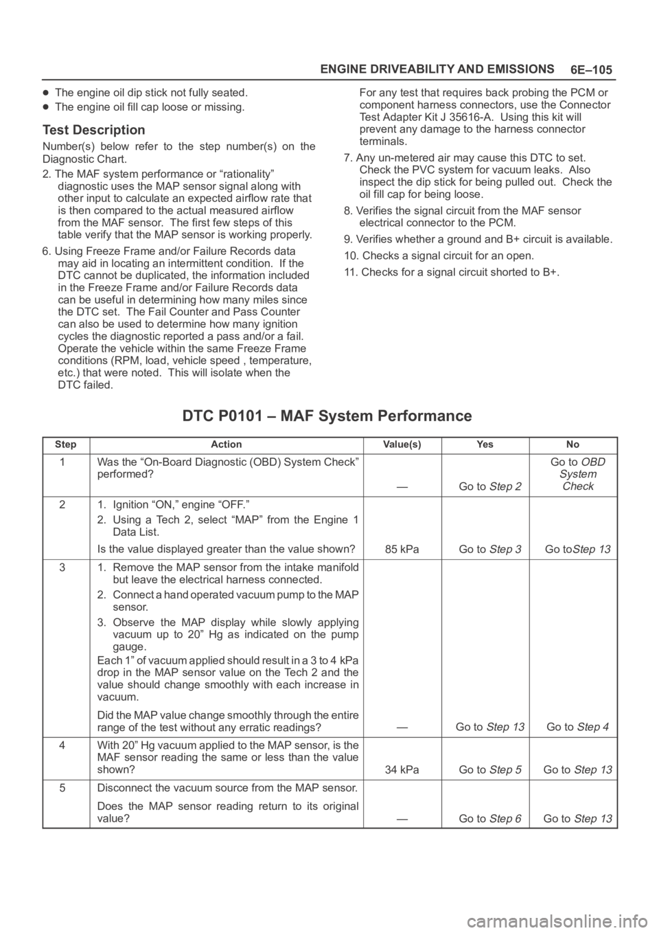
6E–105 ENGINE DRIVEABILITY AND EMISSIONS
The engine oil dip stick not fully seated.
The engine oil fill cap loose or missing.
Test Description
Number(s) below refer to the step number(s) on the
Diagnostic Chart.
2. The MAF system performance or “rationality”
diagnostic uses the MAP sensor signal along with
other input to calculate an expected airflow rate that
is then compared to the actual measured airflow
from the MAF sensor. The first few steps of this
table verify that the MAP sensor is working properly.
6. Using Freeze Frame and/or Failure Records data
may aid in locating an intermittent condition. If the
DTC cannot be duplicated, the information included
in the Freeze Frame and/or Failure Records data
can be useful in determining how many miles since
the DTC set. The Fail Counter and Pass Counter
can also be used to determine how many ignition
cycles the diagnostic reported a pass and/or a fail.
Operate the vehicle within the same Freeze Frame
conditions (RPM, load, vehicle speed , temperature,
etc.) that were noted. This will isolate when the
DTC failed.For any test that requires back probing the PCM or
component harness connectors, use the Connector
Test Adapter Kit J 35616-A. Using this kit will
prevent any damage to the harness connector
terminals.
7. Any un-metered air may cause this DTC to set.
Check the PVC system for vacuum leaks. Also
inspect the dip stick for being pulled out. Check the
oil fill cap for being loose.
8. Verifies the signal circuit from the MAF sensor
electrical connector to the PCM.
9. Verifies whether a ground and B+ circuit is available.
10. Checks a signal circuit for an open.
11. Checks for a signal circuit shorted to B+.
DTC P0101 – MAF System Performance
StepActionVa l u e ( s )Ye sNo
1Was the “On-Board Diagnostic (OBD) System Check”
performed?
—Go to Step 2
Go to OBD
System
Check
21. Ignition “ON,” engine “OFF.”
2. Using a Tech 2, select “MAP” from the Engine 1
Data List.
Is the value displayed greater than the value shown?
85 kPaGo to Step 3Go toStep 13
31. Remove the MAP sensor from the intake manifold
but leave the electrical harness connected.
2. Connect a hand operated vacuum pump to the MAP
sensor.
3. Observe the MAP display while slowly applying
vacuum up to 20” Hg as indicated on the pump
gauge.
Each 1” of vacuum applied should result in a 3 to 4 kPa
drop in the MAP sensor value on the Tech 2 and the
value should change smoothly with each increase in
vacuum.
Did the MAP value change smoothly through the entire
range of the test without any erratic readings?
—Go to Step 13Go to Step 4
4With 20” Hg vacuum applied to the MAP sensor, is the
MAF sensor reading the same or less than the value
shown?
34 kPaGo to Step 5Go to Step 13
5Disconnect the vacuum source from the MAP sensor.
Does the MAP sensor reading return to its original
value?
—Go to Step 6Go to Step 13