1998 OPEL FRONTERA battery
[x] Cancel search: batteryPage 1986 of 6000
6E–93 4JX1–TC ENGINE DRIVEABILITY AND EMISSIONS
Circuit Description
The rail pressure control valve (RPCV) is built in the high
pressure oil circuit.
RPCV is an important device which is used to control oil
pressure in the HEUI system.
The circuit receives current through Engine 15A fuse from
the battery, current flowing in the order of RPCV.
Action Taken When the DTC Sets
The ECM will store conditions which were present
when the DTC was set as Freeze Frame and in the
Failure Records data.
Conditions for Clearing the MIL/DTC
DTC P1196 can be cleared by using the Tech 2 “Clear
Info” function or by disconnecting the ECM battery
feed.
Diagnostic Aids
Check for the following conditions:
Poor connection at ECM – Inspect harness connectors
for backed-out terminals, improper mating, broken
locks, improperly formed or damaged terminals, and
poor terminal-to-wire connection.
Damaged harness – Inspect the wiring harness for
damage. If the harness appears to be OK, observe the
Rail Pressure Control display on the Tech 2 while
moving connectors and wiring harnesses related to the
Rail Pressure Control. A change in the Rail Pressure
Control display will indicate the location of the fault.
If DTC P1196 cannot be duplicated, the information
included in the Failure Records data can be useful in
determining vehicle mileage since the DTC was last set.
If it is determined that the DTC occurs intermittently.
Test Description
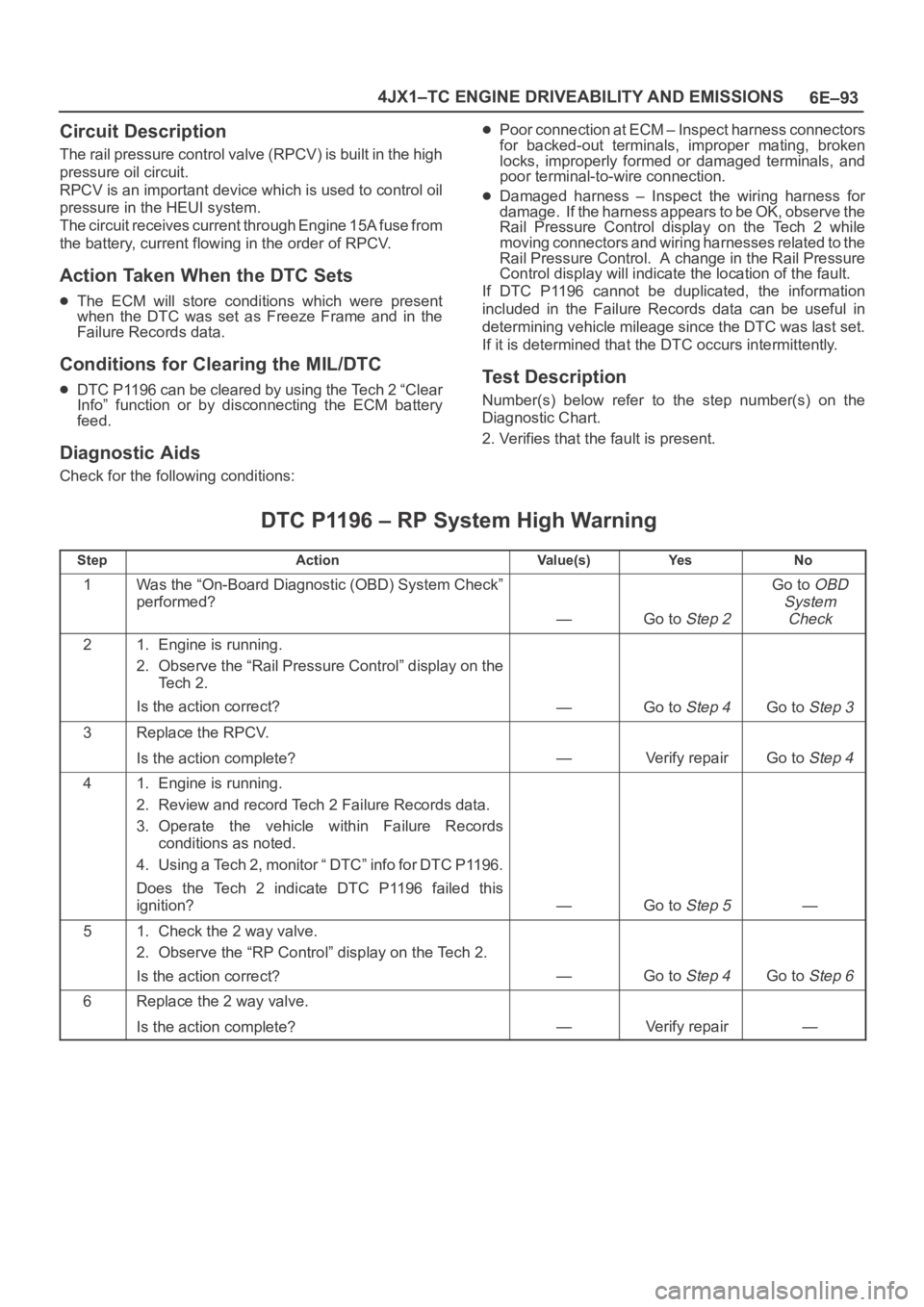
Number(s) below refer to the step number(s) on the
Diagnostic Chart.
2. Verifies that the fault is present.
DTC P1196 – RP System High Warning
StepActionVa l u e ( s )Ye sNo
1Was the “On-Board Diagnostic (OBD) System Check”
performed?
—Go to Step 2
Go to OBD
System
Check
21. Engine is running.
2. Observe the “Rail Pressure Control” display on the
Te c h 2 .
Is the action correct?
—Go to Step 4Go to Step 3
3Replace the RPCV.
Is the action complete?
—Verify repairGo to Step 4
41. Engine is running.
2. Review and record Tech 2 Failure Records data.
3. Operate the vehicle within Failure Records
conditions as noted.
4. Using a Tech 2, monitor “ DTC” info for DTC P1196.
Does the Tech 2 indicate DTC P1196 failed this
ignition?
—Go to Step 5—
51. Check the 2 way valve.
2. Observe the “RP Control” display on the Tech 2.
Is the action correct?
—Go to Step 4Go to Step 6
6Replace the 2 way valve.
Is the action complete?
—Verify repair—
Page 1987 of 6000
6E–94
4JX1–TC ENGINE DRIVEABILITY AND EMISSIONS
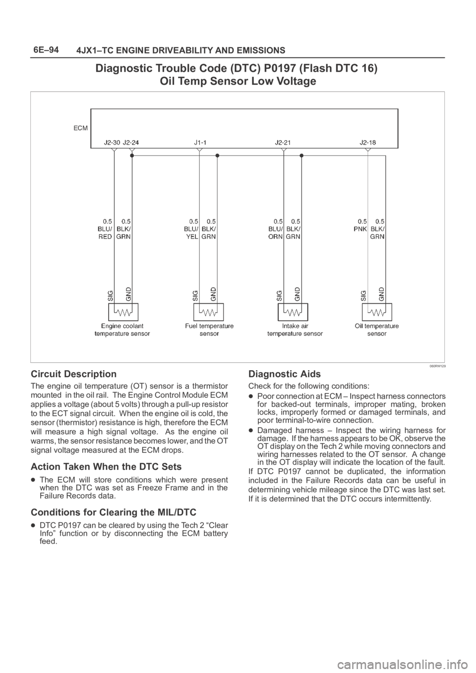
Diagnostic Trouble Code (DTC) P0197 (Flash DTC 16)
Oil Temp Sensor Low Voltage
060RW129
Circuit Description
The engine oil temperature (OT) sensor is a thermistor
mounted in the oil rail. The Engine Control Module ECM
applies a voltage (about 5 volts) through a pull-up resistor
to the ECT signal circuit. When the engine oil is cold, the
sensor (thermistor) resistance is high, therefore the ECM
will measure a high signal voltage. As the engine oil
warms, the sensor resistance becomes lower, and the OT
signal voltage measured at the ECM drops.
Action Taken When the DTC Sets
The ECM will store conditions which were present
when the DTC was set as Freeze Frame and in the
Failure Records data.
Conditions for Clearing the MIL/DTC
DTC P0197 can be cleared by using the Tech 2 “Clear
Info” function or by disconnecting the ECM battery
feed.
Diagnostic Aids
Check for the following conditions:
Poor connection at ECM – Inspect harness connectors
for backed-out terminals, improper mating, broken
locks, improperly formed or damaged terminals, and
poor terminal-to-wire connection.
Damaged harness – Inspect the wiring harness for
damage. If the harness appears to be OK, observe the
OT display on the Tech 2 while moving connectors and
wiring harnesses related to the OT sensor. A change
in the OT display will indicate the location of the fault.
If DTC P0197 cannot be duplicated, the information
included in the Failure Records data can be useful in
determining vehicle mileage since the DTC was last set.
If it is determined that the DTC occurs intermittently.
Page 1989 of 6000
6E–96
4JX1–TC ENGINE DRIVEABILITY AND EMISSIONS
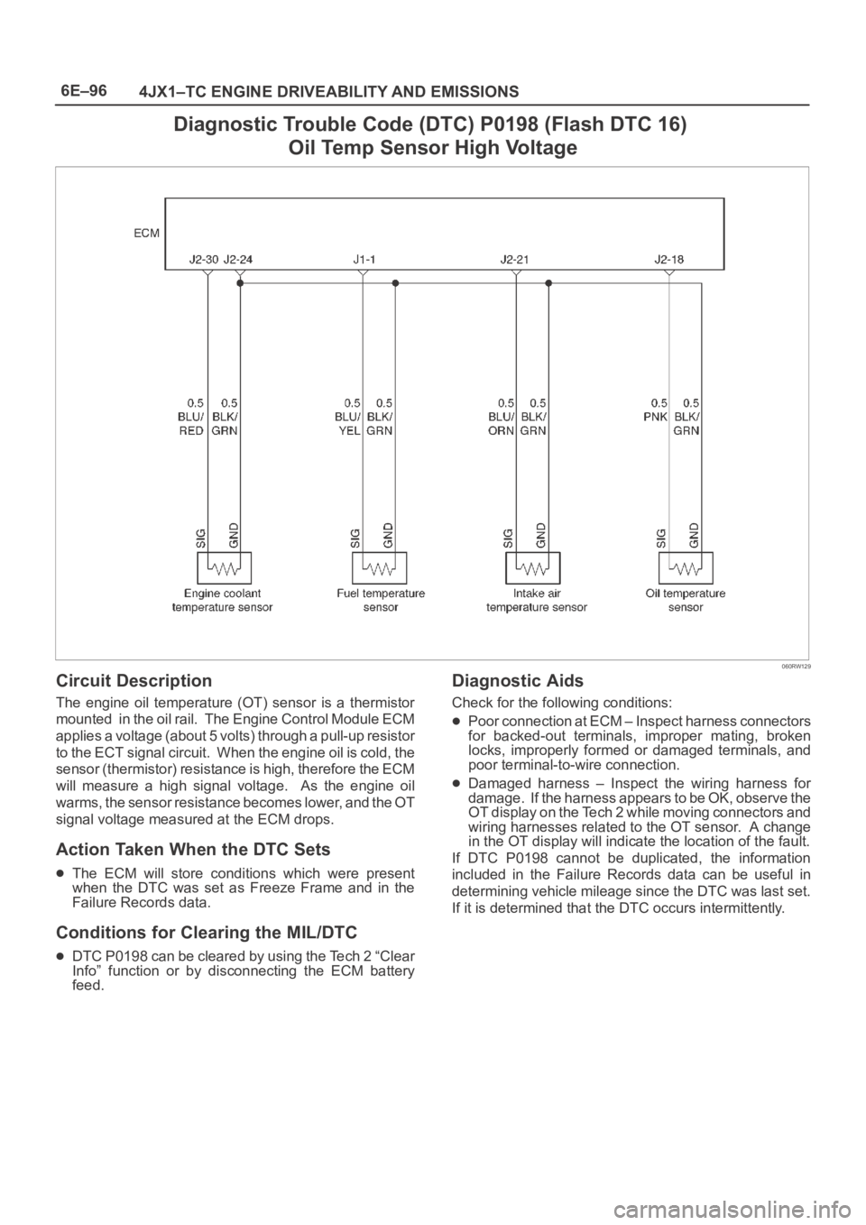
Diagnostic Trouble Code (DTC) P0198 (Flash DTC 16)
Oil Temp Sensor High Voltage
060RW129
Circuit Description
The engine oil temperature (OT) sensor is a thermistor
mounted in the oil rail. The Engine Control Module ECM
applies a voltage (about 5 volts) through a pull-up resistor
to the ECT signal circuit. When the engine oil is cold, the
sensor (thermistor) resistance is high, therefore the ECM
will measure a high signal voltage. As the engine oil
warms, the sensor resistance becomes lower, and the OT
signal voltage measured at the ECM drops.
Action Taken When the DTC Sets
The ECM will store conditions which were present
when the DTC was set as Freeze Frame and in the
Failure Records data.
Conditions for Clearing the MIL/DTC
DTC P0198 can be cleared by using the Tech 2 “Clear
Info” function or by disconnecting the ECM battery
feed.
Diagnostic Aids
Check for the following conditions:
Poor connection at ECM – Inspect harness connectors
for backed-out terminals, improper mating, broken
locks, improperly formed or damaged terminals, and
poor terminal-to-wire connection.
Damaged harness – Inspect the wiring harness for
damage. If the harness appears to be OK, observe the
OT display on the Tech 2 while moving connectors and
wiring harnesses related to the OT sensor. A change
in the OT display will indicate the location of the fault.
If DTC P0198 cannot be duplicated, the information
included in the Failure Records data can be useful in
determining vehicle mileage since the DTC was last set.
If it is determined that the DTC occurs intermittently.
Page 1992 of 6000
6E–99 4JX1–TC ENGINE DRIVEABILITY AND EMISSIONS
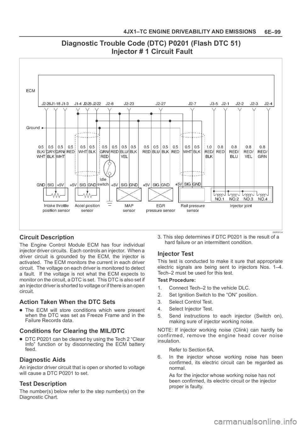
Diagnostic Trouble Code (DTC) P0201 (Flash DTC 51)
Injector # 1 Circuit Fault
060RW134
Circuit Description
The Engine Control Module ECM has four individual
injector driver circuits. Each controls an injector. When a
driver circuit is grounded by the ECM, the injector is
activated. The ECM monitors the current in each driver
circuit. The voltage on each driver is monitored to detect
a fault. If the voltage is not what the ECM expects to
m o n i t o r o n t h e c i r c u i t , a D T C i s s e t . T h i s D T C i s a l s o s e t i f
an injector driver is shorted to voltage or if there is an open
circuit.
Action Taken When the DTC Sets
The ECM will store conditions which were present
when the DTC was set as Freeze Frame and in the
Failure Records data.
Conditions for Clearing the MIL/DTC
DTC P0201 can be cleared by using the Tech 2 “Clear
Info” function or by disconnecting the ECM battery
feed.
Diagnostic Aids
An injector driver circuit that is open or shorted to voltage
will cause a DTC P0201 to set.
Test Description
The number(s) below refer to the step number(s) on the
Diagnostic Chart.3. This step determines if DTC P0201 is the result of a
hard failure or an intermittent condition.
Injector Test
This test is conducted to make it sure that appropriate
electric signals are being sent to injectors Nos. 1–4.
Tech–2 must be used for this test.
Test Procedure:
1. Connect Tech–2 to the vehicle DLC.
2. Set Ignition Switch to the “ON” position.
3. Select Control Test.
4. Select Injector Test.
5. Send instructions to each injector (Switch on),
making sure of injector working noise.
NOTE: If injector working noise (Clink) can hardly be
confirmed, remove the engine head cover noise
insulation.
Refer to Section 6A.
6. In the injector whose working noise has been
confirmed, its electric circuit can be regarded as
normal.
As for the injector whose working noise has not
been confirmed, its electric circuit or the injector
proper is faulty.
Page 1994 of 6000
6E–101 4JX1–TC ENGINE DRIVEABILITY AND EMISSIONS
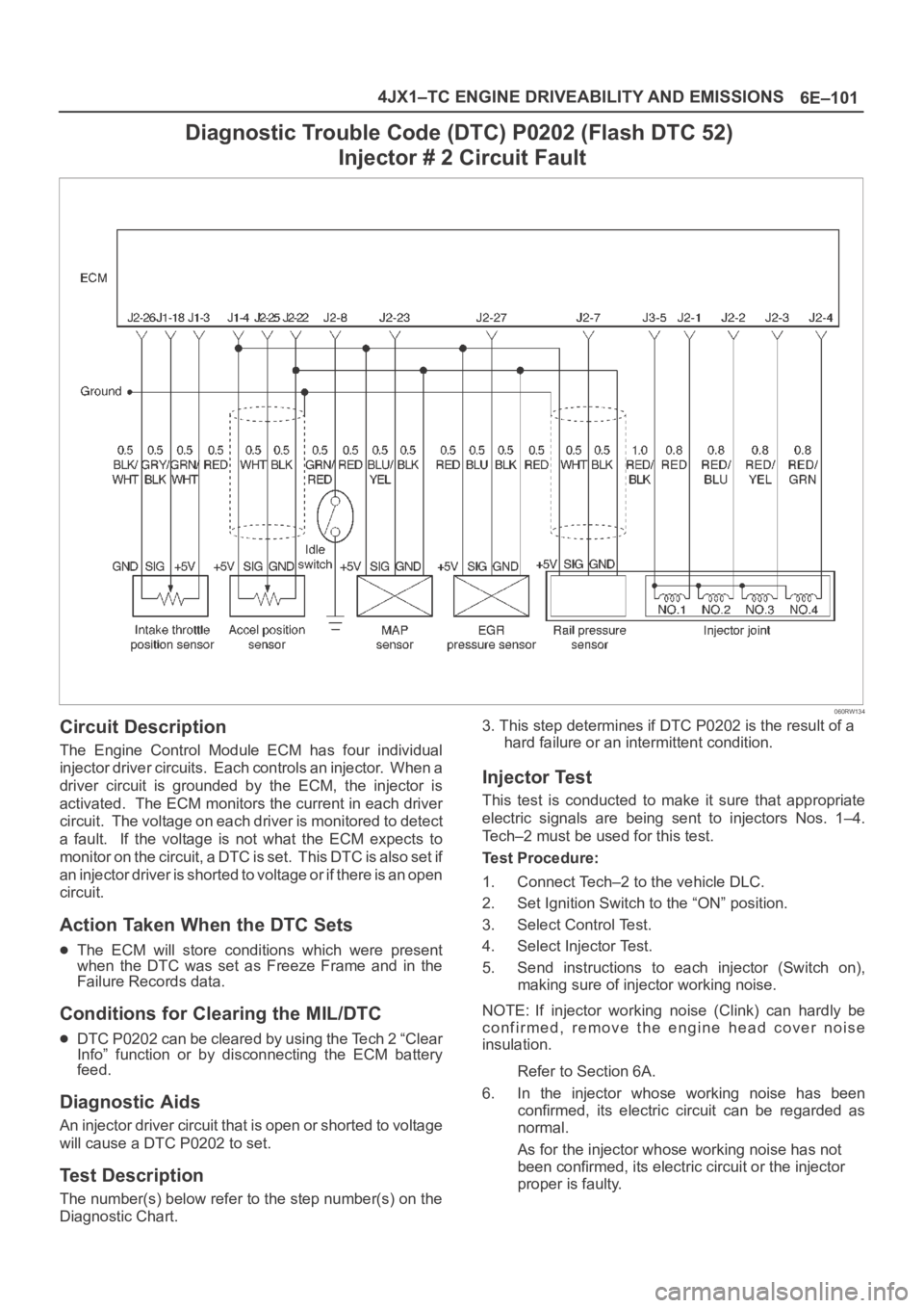
Diagnostic Trouble Code (DTC) P0202 (Flash DTC 52)
Injector # 2 Circuit Fault
060RW134
Circuit Description
The Engine Control Module ECM has four individual
injector driver circuits. Each controls an injector. When a
driver circuit is grounded by the ECM, the injector is
activated. The ECM monitors the current in each driver
circuit. The voltage on each driver is monitored to detect
a fault. If the voltage is not what the ECM expects to
m o n i t o r o n t h e c i r c u i t , a D T C i s s e t . T h i s D T C i s a l s o s e t i f
an injector driver is shorted to voltage or if there is an open
circuit.
Action Taken When the DTC Sets
The ECM will store conditions which were present
when the DTC was set as Freeze Frame and in the
Failure Records data.
Conditions for Clearing the MIL/DTC
DTC P0202 can be cleared by using the Tech 2 “Clear
Info” function or by disconnecting the ECM battery
feed.
Diagnostic Aids
An injector driver circuit that is open or shorted to voltage
will cause a DTC P0202 to set.
Test Description
The number(s) below refer to the step number(s) on the
Diagnostic Chart.3. This step determines if DTC P0202 is the result of a
hard failure or an intermittent condition.
Injector Test
This test is conducted to make it sure that appropriate
electric signals are being sent to injectors Nos. 1–4.
Tech–2 must be used for this test.
Test Procedure:
1. Connect Tech–2 to the vehicle DLC.
2. Set Ignition Switch to the “ON” position.
3. Select Control Test.
4. Select Injector Test.
5. Send instructions to each injector (Switch on),
making sure of injector working noise.
NOTE: If injector working noise (Clink) can hardly be
confirmed, remove the engine head cover noise
insulation.
Refer to Section 6A.
6. In the injector whose working noise has been
confirmed, its electric circuit can be regarded as
normal.
As for the injector whose working noise has not
been confirmed, its electric circuit or the injector
proper is faulty.
Page 1996 of 6000
6E–103 4JX1–TC ENGINE DRIVEABILITY AND EMISSIONS
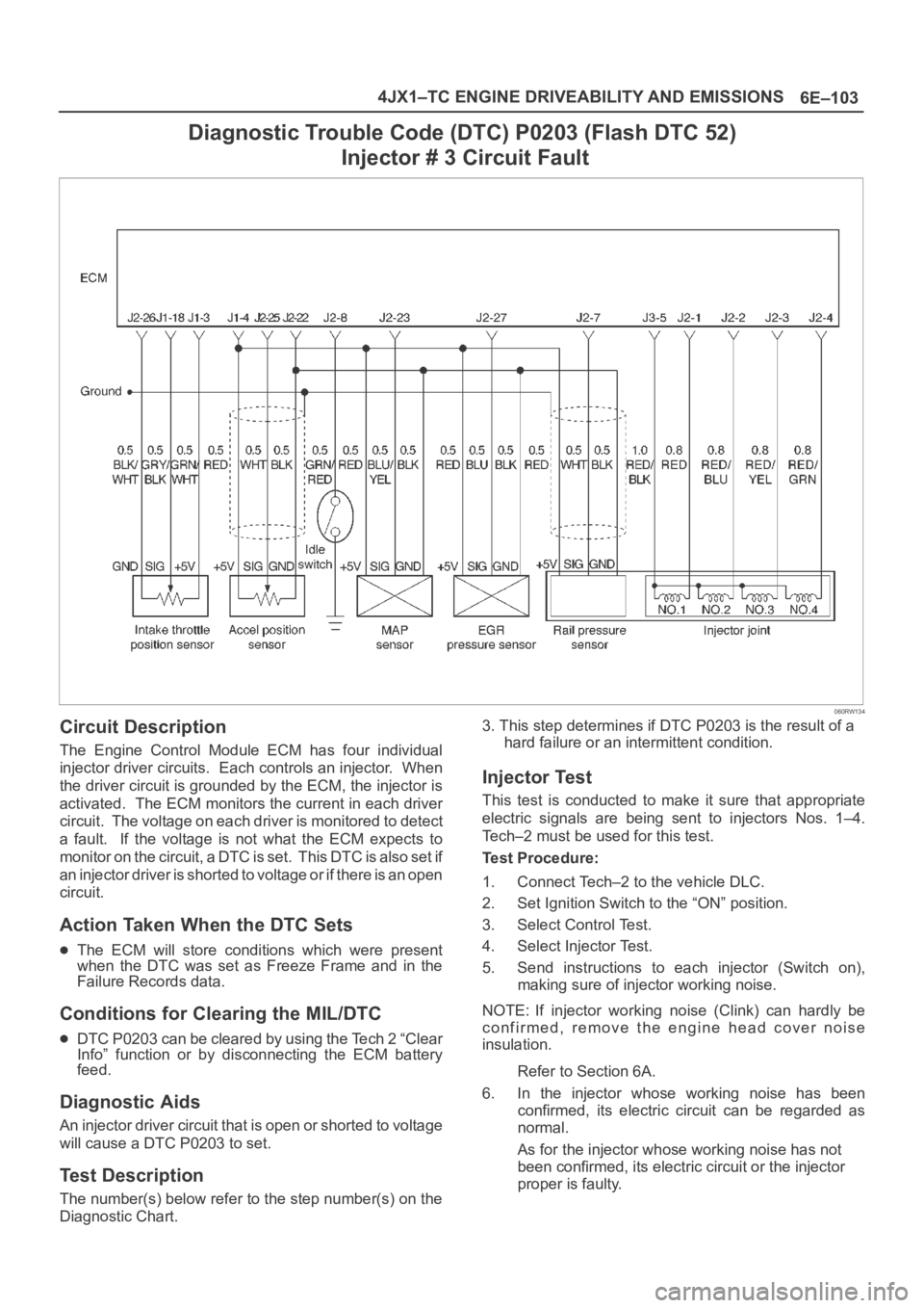
Diagnostic Trouble Code (DTC) P0203 (Flash DTC 52)
Injector # 3 Circuit Fault
060RW134
Circuit Description
The Engine Control Module ECM has four individual
injector driver circuits. Each controls an injector. When
the driver circuit is grounded by the ECM, the injector is
activated. The ECM monitors the current in each driver
circuit. The voltage on each driver is monitored to detect
a fault. If the voltage is not what the ECM expects to
m o n i t o r o n t h e c i r c u i t , a D T C i s s e t . T h i s D T C i s a l s o s e t i f
an injector driver is shorted to voltage or if there is an open
circuit.
Action Taken When the DTC Sets
The ECM will store conditions which were present
when the DTC was set as Freeze Frame and in the
Failure Records data.
Conditions for Clearing the MIL/DTC
DTC P0203 can be cleared by using the Tech 2 “Clear
Info” function or by disconnecting the ECM battery
feed.
Diagnostic Aids
An injector driver circuit that is open or shorted to voltage
will cause a DTC P0203 to set.
Test Description
The number(s) below refer to the step number(s) on the
Diagnostic Chart.3. This step determines if DTC P0203 is the result of a
hard failure or an intermittent condition.
Injector Test
This test is conducted to make it sure that appropriate
electric signals are being sent to injectors Nos. 1–4.
Tech–2 must be used for this test.
Test Procedure:
1. Connect Tech–2 to the vehicle DLC.
2. Set Ignition Switch to the “ON” position.
3. Select Control Test.
4. Select Injector Test.
5. Send instructions to each injector (Switch on),
making sure of injector working noise.
NOTE: If injector working noise (Clink) can hardly be
confirmed, remove the engine head cover noise
insulation.
Refer to Section 6A.
6. In the injector whose working noise has been
confirmed, its electric circuit can be regarded as
normal.
As for the injector whose working noise has not
been confirmed, its electric circuit or the injector
proper is faulty.
Page 1998 of 6000
6E–105 4JX1–TC ENGINE DRIVEABILITY AND EMISSIONS
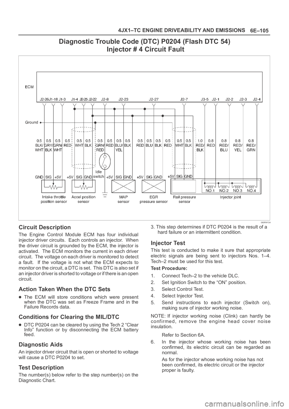
Diagnostic Trouble Code (DTC) P0204 (Flash DTC 54)
Injector # 4 Circuit Fault
060RW134
Circuit Description
The Engine Control Module ECM has four individual
injector driver circuits. Each controls an injector. When
the driver circuit is grounded by the ECM, the injector is
activated. The ECM monitors the current in each driver
circuit. The voltage on each driver is monitored to detect
a fault. If the voltage is not what the ECM expects to
m o n i t o r o n t h e c i r c u i t , a D T C i s s e t . T h i s D T C i s a l s o s e t i f
an injector driver is shorted to voltage or if there is an open
circuit.
Action Taken When the DTC Sets
The ECM will store conditions which were present
when the DTC was set as Freeze Frame and in the
Failure Records data.
Conditions for Clearing the MIL/DTC
DTC P0204 can be cleared by using the Tech 2 “Clear
Info” function or by disconnecting the ECM battery
feed.
Diagnostic Aids
An injector driver circuit that is open or shorted to voltage
will cause a DTC P0204 to set.
Test Description
The number(s) below refer to the step number(s) on the
Diagnostic Chart.3. This step determines if DTC P0204 is the result of a
hard failure or an intermittent condition.
Injector Test
This test is conducted to make it sure that appropriate
electric signals are being sent to injectors Nos. 1–4.
Tech–2 must be used for this test.
Test Procedure:
1. Connect Tech–2 to the vehicle DLC.
2. Set Ignition Switch to the “ON” position.
3. Select Control Test.
4. Select Injector Test.
5. Send instructions to each injector (Switch on),
making sure of injector working noise.
NOTE: If injector working noise (Clink) can hardly be
confirmed, remove the engine head cover noise
insulation.
Refer to Section 6A.
6. In the injector whose working noise has been
confirmed, its electric circuit can be regarded as
normal.
As for the injector whose working noise has not
been confirmed, its electric circuit or the injector
proper is faulty.
Page 2000 of 6000
6E–107 4JX1–TC ENGINE DRIVEABILITY AND EMISSIONS
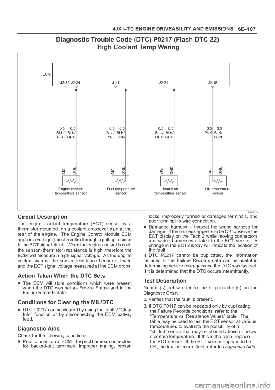
Diagnostic Trouble Code (DTC) P0217 (Flash DTC 22)
High Coolant Temp Waring
060RW129
Circuit Description
The engine coolant temperature (ECT) sensor is a
thermistor mounted on a coolant crossover pipe at the
rear of the engine. The Engine Control Module ECM
applies a voltage (about 5 volts) through a pull-up resistor
to the ECT signal circuit. When the engine coolant is cold,
the sensor (thermistor) resistance is high, therefore the
ECM will measure a high signal voltage. As the engine
coolant warms, the sensor resistance becomes lower,
and the ECT signal voltage measured at the ECM drops.
Action Taken When the DTC Sets
The ECM will store conditions which were present
when the DTC was set as Freeze Frame and in the
Failure Records data.
Conditions for Clearing the MIL/DTC
DTC P0217 can be cleared by using the Tech 2 “Clear
Info” function or by disconnecting the ECM battery
feed.
Diagnostic Aids
Check for the following conditions:
Poor connection at ECM – Inspect harness connectors
for backed-out terminals, improper mating, brokenlocks, improperly formed or damaged terminals, and
poor terminal-to-wire connection.
Damaged harness – Inspect the wiring harness for
damage. If the harness appears to be OK, observe the
ECT display on the Tech 2 while moving connectors
and wiring harnesses related to the ECT sensor. A
change in the ECT display will indicate the location of
the fault.
If DTC P0217 cannot be duplicated, the information
included in the Failure Records data can be useful in
determining vehicle mileage since the DTC was last set.
If it is determined that the DTC occurs intermittently.
Test Description
Number(s) below refer to the step number(s) on the
Diagnostic Chart.
2. Verifies that the fault is present.
3. If DTC P0117 can be repeated only by duplicating
the Failure Records conditions, refer to the
“Temperature vs. Resistance Values” table. The
table may be used to test the ECT sensor at various
temperatures to evaluate the possibility of a
“shifted” sensor that may be shorted above or below
a certain temperature. If this is the case, replace
the ECT sensor. If the ECT sensor appears to be
OK, the fault is intermittent; refer to
Diagnostic Aids.