1998 OPEL FRONTERA battery
[x] Cancel search: batteryPage 1888 of 6000
ENGINE ELECTRICAL 6D – 21
Rectifier Assembly
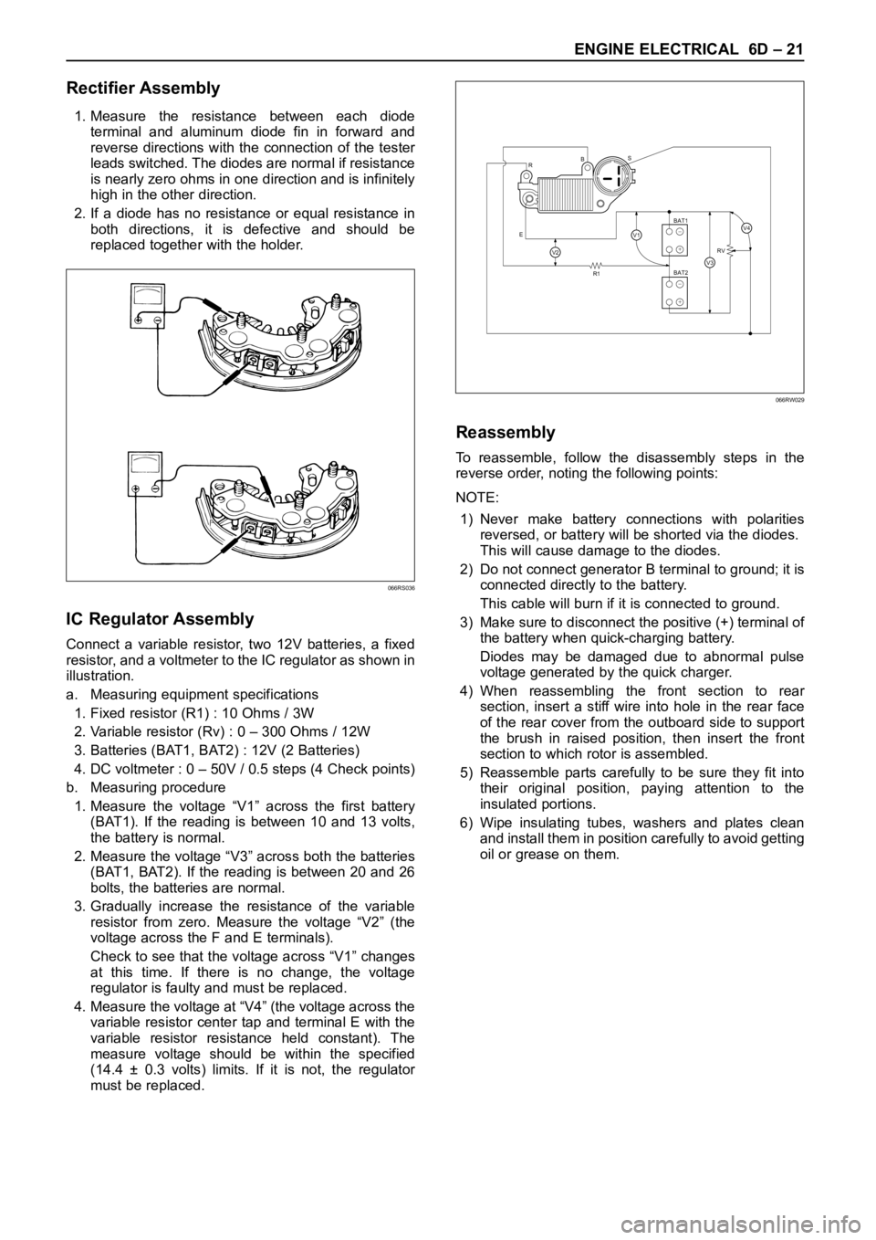
1. Measure the resistance between each diode
terminal and aluminum diode fin in forward and
reverse directions with the connection of the tester
leads switched. The diodes are normal if resistance
is nearly zero ohms in one direction and is infinitely
high in the other direction.
2. If a diode has no resistance or equal resistance in
both directions, it is defective and should be
replaced together with the holder.
IC Regulator Assembly
Connect a variable resistor, two 12V batteries, a fixed
resistor, and a voltmeter to the IC regulator as shown in
illustration.
a. Measuring equipment specifications
1. Fixed resistor (R1) : 10 Ohms / 3W
2. Variable resistor (Rv) : 0 – 300 Ohms / 12W
3. Batteries (BAT1, BAT2) : 12V (2 Batteries)
4. DC voltmeter : 0 – 50V / 0.5 steps (4 Check points)
b. Measuring procedure
1. Measure the voltage “V1” across the first battery
(BAT1). If the reading is between 10 and 13 volts,
the battery is normal.
2. Measure the voltage “V3” across both the batteries
(BAT1, BAT2). If the reading is between 20 and 26
bolts, the batteries are normal.
3. Gradually increase the resistance of the variable
resistor from zero. Measure the voltage “V2” (the
voltage across the F and E terminals).
Check to see that the voltage across “V1” changes
at this time. If there is no change, the voltage
regulator is faulty and must be replaced.
4. Measure the voltage at “V4” (the voltage across the
variable resistor center tap and terminal E with the
variable resistor resistance held constant). The
measure voltage should be within the specified
(14.4 ± 0.3 volts) limits. If it is not, the regulator
must be replaced.
Reassembly
To reassemble, follow the disassembly steps in the
reverse order, noting the following points:
NOTE:
1) Never make battery connections with polarities
reversed, or battery will be shorted via the diodes.
This will cause damage to the diodes.
2) Do not connect generator B terminal to ground; it is
connected directly to the battery.
This cable will burn if it is connected to ground.
3) Make sure to disconnect the positive (+) terminal of
the battery when quick-charging battery.
Diodes may be damaged due to abnormal pulse
voltage generated by the quick charger.
4) When reassembling the front section to rear
section, insert a stiff wire into hole in the rear face
of the rear cover from the outboard side to support
the brush in raised position, then insert the front
section to which rotor is assembled.
5) Reassemble parts carefully to be sure they fit into
their original position, paying attention to the
insulated portions.
6) Wipe insulating tubes, washers and plates clean
and install them in position carefully to avoid getting
oil or grease on them.
066RS036
R
EBS
R1RV
BAT2 BAT1
V2V3
V4V1+
−
+
−
066RW029
Page 1889 of 6000
6D – 22 ENGINE ELECTRICAL
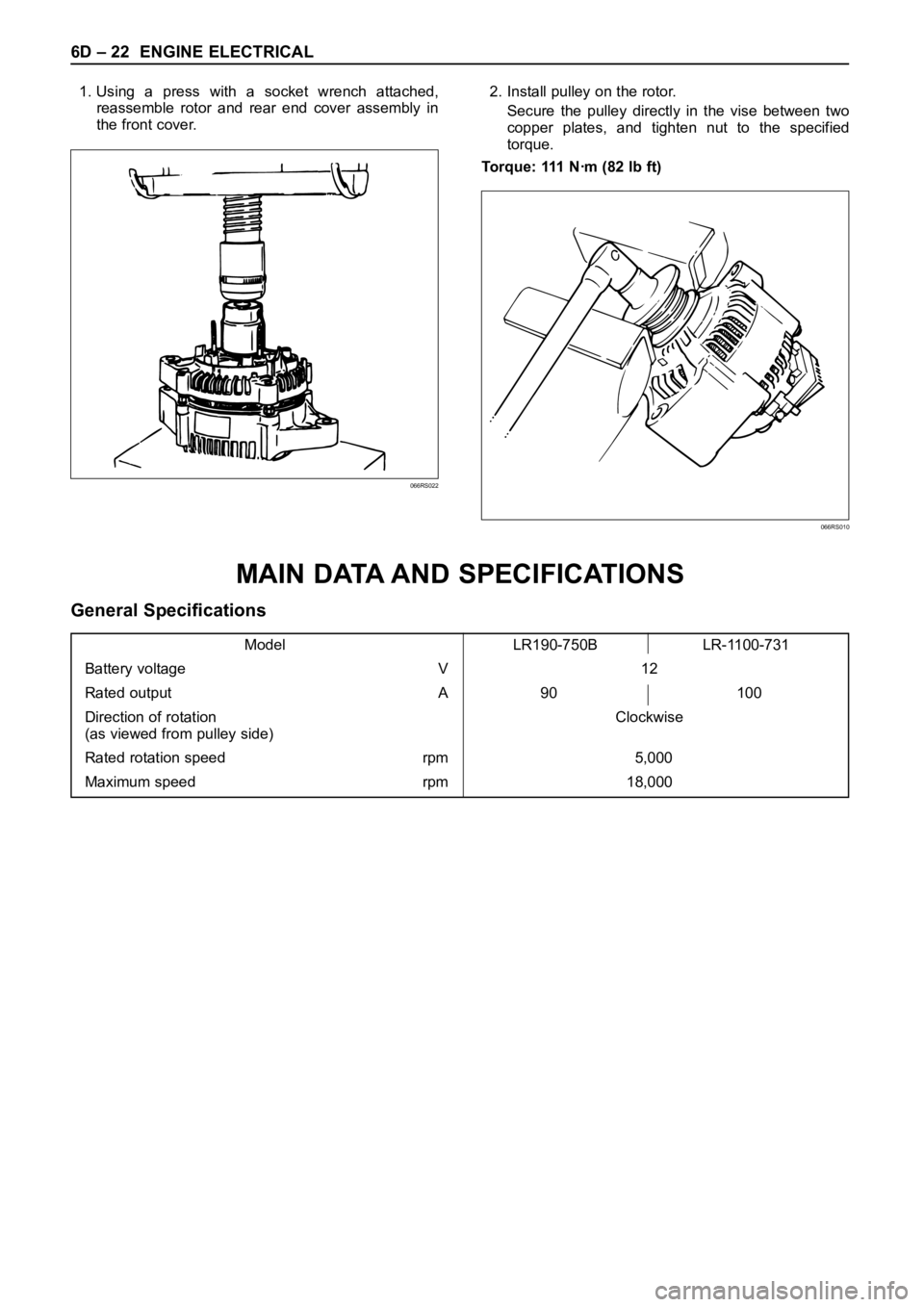
1. Using a press with a socket wrench attached,
reassemble rotor and rear end cover assembly in
the front cover.2. Install pulley on the rotor.
Secure the pulley directly in the vise between two
copper plates, and tighten nut to the specified
torque.
Torque: 111 Nꞏm (82 lb ft)
066RS022
066RS010
MAIN DATA AND SPECIFICATIONS
General Specifications
Model LR190-750B LR-1100-731
Battery voltage V 12
Rated output A 90 100
Direction of rotation Clockwise
(as viewed from pulley side)
Rated rotation speed rpm 5,000
Maximum speed rpm 18,000
Page 1891 of 6000
6D – 24 ENGINE ELECTRICAL
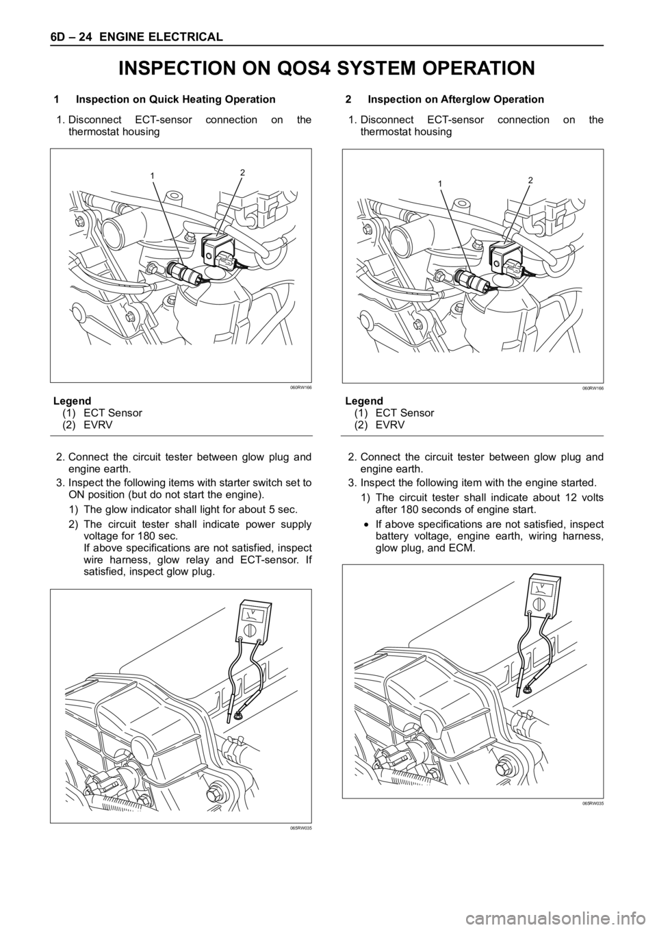
1 Inspection on Quick Heating Operation
1. Disconnect ECT-sensor connection on the
thermostat housing
Legend
(1) ECT Sensor
(2) EVRV
2. Connect the circuit tester between glow plug and
engine earth.
3. Inspect the following items with starter switch set to
ON position (but do not start the engine).
1) The glow indicator shall light for about 5 sec.
2) The circuit tester shall indicate power supply
voltage for 180 sec.
If above specifications are not satisfied, inspect
wire harness, glow relay and ECT-sensor. If
satisfied, inspect glow plug.2 Inspection on Afterglow Operation
1. Disconnect ECT-sensor connection on the
thermostat housing
Legend
(1) ECT Sensor
(2) EVRV
2. Connect the circuit tester between glow plug and
engine earth.
3. Inspect the following item with the engine started.
1) The circuit tester shall indicate about 12 volts
after 180 seconds of engine start.
If above specifications are not satisfied, inspect
battery voltage, engine earth, wiring harness,
glow plug, and ECM.
12
060RW166
065RW035
12
060RW166
065RW035
INSPECTION ON QOS4 SYSTEM OPERATION
Page 1892 of 6000

ENGINE ELECTRICAL 6D – 25
ECT SENSOR
Measure the resistance depending on the water
temperature.
Temperature (°C) Current (mA) Resistance (k
)
20 ± 1 1.0 2.0 – 3.0
50 ± 1 1.0 0.6 – 1.0
When installing the ECT sensor, apply sealant (Loctite
#262 or equivalent) to prevent water leakage.
Torque: 8 Nꞏm (0.8 kgꞏm/69 lb in)
Legend
(1) Sealing Material
GLOW PLUG
Inspect the resistance
Resistance at normal temperature: 0.8 – 1.0
Torque: 23 Nꞏm (2.3 kgꞏm/17 lbꞏft)
GLOW PLUG RELAY
Inspect the continuity
(2) – (4) No Continuity
(1) – (3) Continuity
If battery voltage is applied to the terminal between (1)
– (3)
(2) – (4) Continuity065RW058
065RW061
1
065RW060
2 42
311
34
065RW037
Page 1909 of 6000
6E–16
4JX1–TC ENGINE DRIVEABILITY AND EMISSIONS
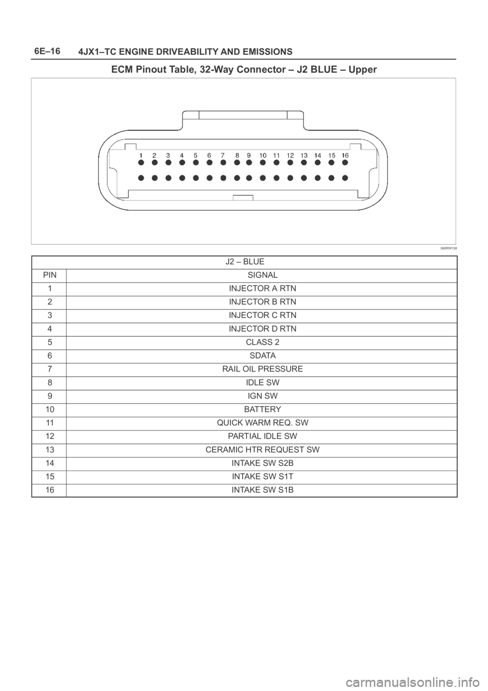
ECM Pinout Table, 32-Way Connector – J2 BLUE – Upper
060RW138
J2 – BLUE
PINSIGNAL
1INJECTOR A RTN
2INJECTOR B RTN
3INJECTOR C RTN
4INJECTOR D RTN
5CLASS 2
6SDATA
7RAIL OIL PRESSURE
8IDLE SW
9IGN SW
10BATTERY
11QUICK WARM REQ. SW
12PARTIAL IDLE SW
13CERAMIC HTR REQUEST SW
14INTAKE SW S2B
15INTAKE SW S1T
16INTAKE SW S1B
Page 1921 of 6000
6E–28
4JX1–TC ENGINE DRIVEABILITY AND EMISSIONS
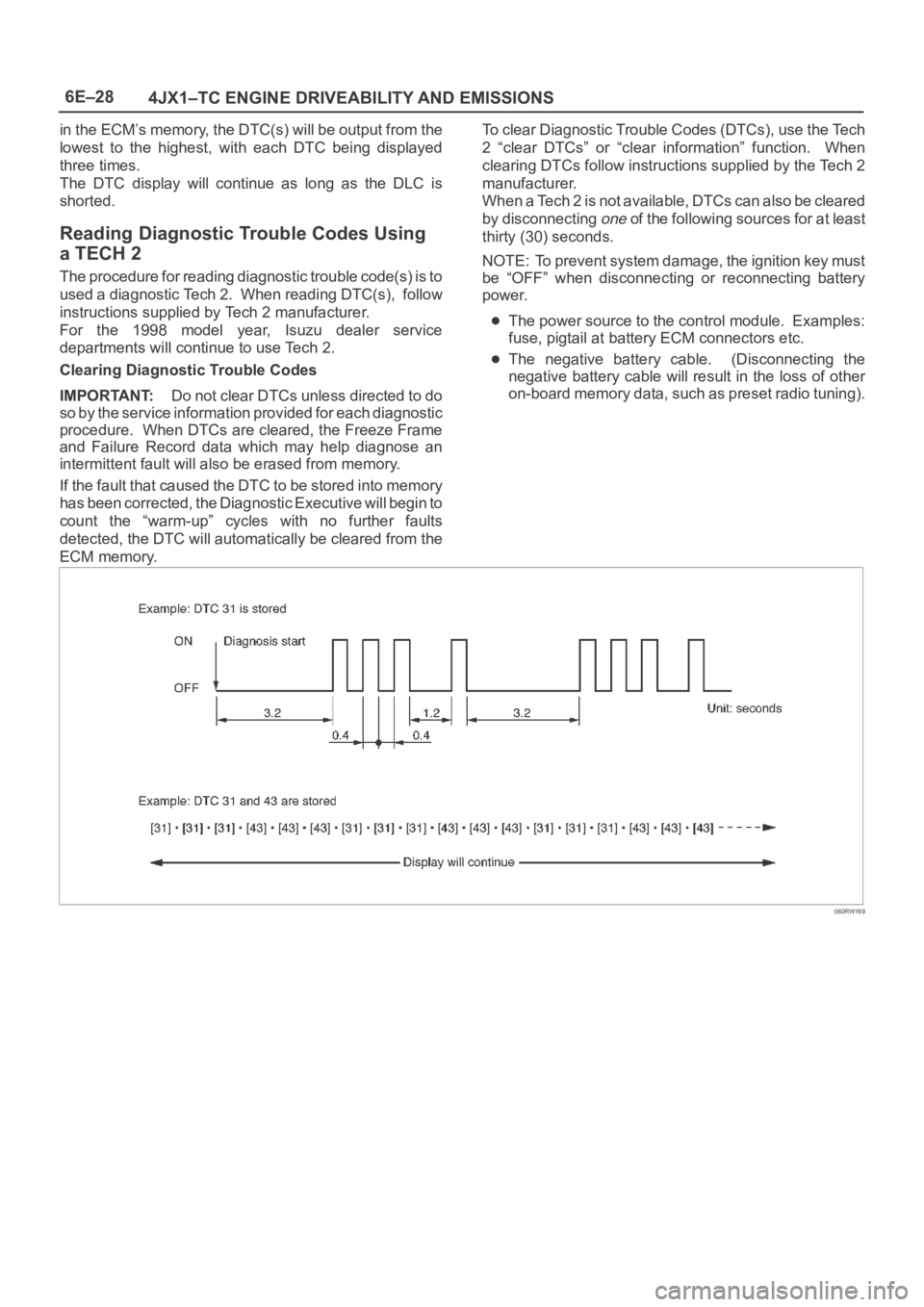
in the ECM’s memory, the DTC(s) will be output from the
lowest to the highest, with each DTC being displayed
three times.
The DTC display will continue as long as the DLC is
shorted.
Reading Diagnostic Trouble Codes Using
a TECH 2
The procedure for reading diagnostic trouble code(s) is to
used a diagnostic Tech 2. When reading DTC(s), follow
instructions supplied by Tech 2 manufacturer.
For the 1998 model year, Isuzu dealer service
departments will continue to use Tech 2.
Clearing Diagnostic Trouble Codes
IMPORTANT:Do not clear DTCs unless directed to do
so by the service information provided for each diagnostic
procedure. When DTCs are cleared, the Freeze Frame
and Failure Record data which may help diagnose an
intermittent fault will also be erased from memory.
If the fault that caused the DTC to be stored into memory
has been corrected, the Diagnostic Executive will begin to
count the “warm-up” cycles with no further faults
detected, the DTC will automatically be cleared from the
ECM memory.To clear Diagnostic Trouble Codes (DTCs), use the Tech
2 “clear DTCs” or “clear information” function. When
clearing DTCs follow instructions supplied by the Tech 2
manufacturer.
When a Tech 2 is not available, DTCs can also be cleared
by disconnecting
one of the following sources for at least
thirty (30) seconds.
NOTE: To prevent system damage, the ignition key must
be “OFF” when disconnecting or reconnecting battery
power.
The power source to the control module. Examples:
fuse, pigtail at battery ECM connectors etc.
The negative battery cable. (Disconnecting the
negative battery cable will result in the loss of other
on-board memory data, such as preset radio tuning).
060RW169
Page 1927 of 6000
6E–34
4JX1–TC ENGINE DRIVEABILITY AND EMISSIONS
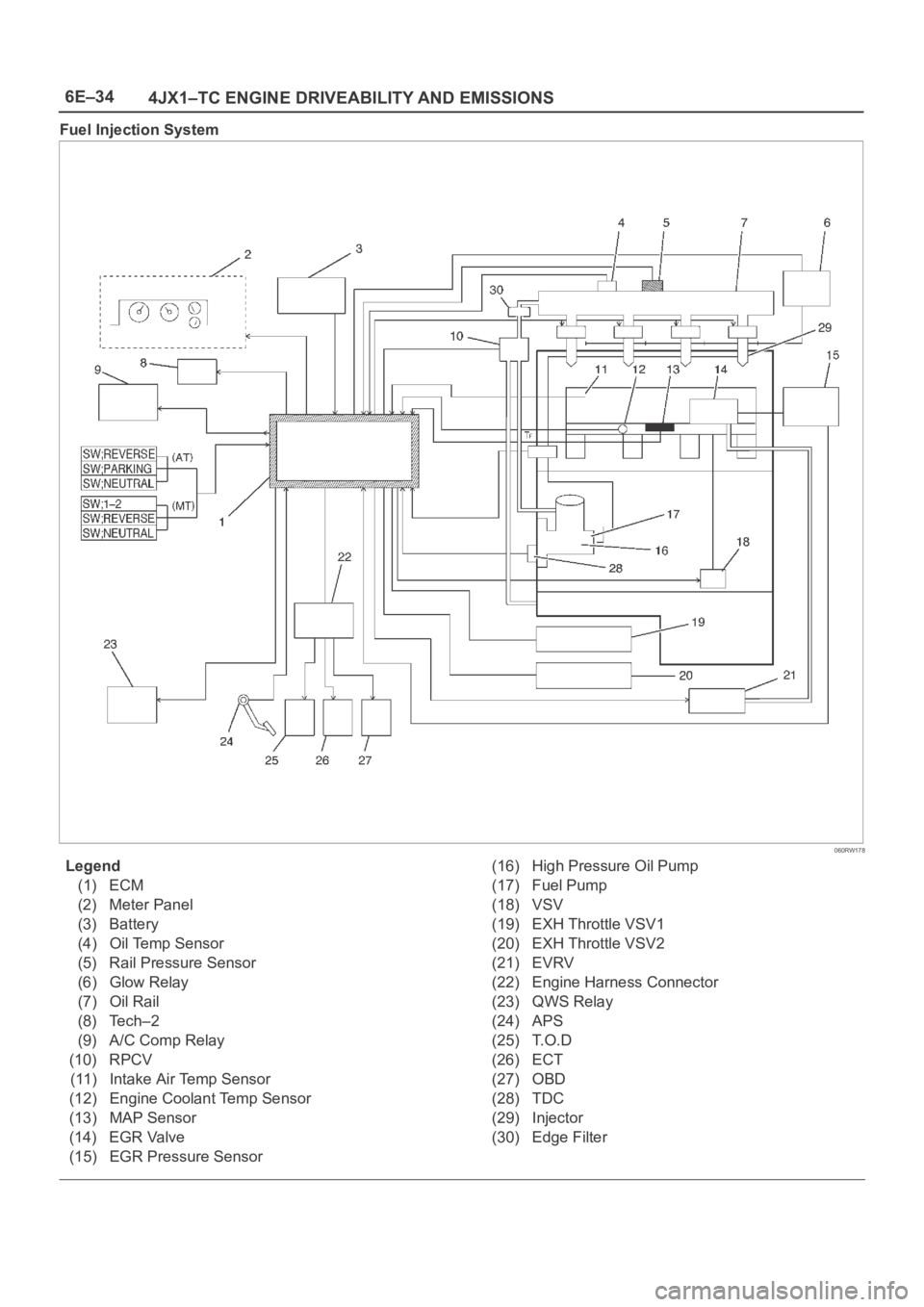
Fuel Injection System
060RW178
Legend
(1) ECM
(2) Meter Panel
(3) Battery
(4) Oil Temp Sensor
(5) Rail Pressure Sensor
(6) Glow Relay
(7) Oil Rail
(8) Tech–2
(9) A/C Comp Relay
(10) RPCV
(11) Intake Air Temp Sensor
(12) Engine Coolant Temp Sensor
(13) MAP Sensor
(14) EGR Valve
(15) EGR Pressure Sensor(16) High Pressure Oil Pump
(17) Fuel Pump
(18) VSV
(19) EXH Throttle VSV1
(20) EXH Throttle VSV2
(21) EVRV
(22) Engine Harness Connector
(23) QWS Relay
(24) APS
(25) T.O.D
(26) ECT
(27) OBD
(28) TDC
(29) Injector
(30) Edge Filter
Page 1932 of 6000
6E–39 4JX1–TC ENGINE DRIVEABILITY AND EMISSIONS
Engine Control Module ECM
Diagnosis
To read and clear diagnostic trouble codes, use a Tech 2.
IMPORTANT:Use of a Tech 2 is recommended to clear
diagnostic trouble codes from the ECM memory.
Diagnostic trouble codes can also be cleared by turning
the ignition “OFF” and disconnecting the battery power
from the ECM for 30 seconds. Turning off the ignition and
disconnecting the battery power from the ECM will cause
all diagnostic information in the ECM memory to be
cleared. Therefore, all the diagnostic tests will have to be
re-run.
Since the ECM can have a failure which may affect only
one circuit, following the diagnostic procedures in this
section will determine which circuit has a problem and
where it is.
If a diagnostic chart indicates that the ECM connections
or the ECM is the cause of a problem, and the ECM is
replaced, but this does not correct the problem, one of the
following may be the reason:
There is a problem with the ECM terminal
connections. The terminals may have to be removed
from the connector in order to check them properly.
The problem is intermittent. This means that the
problem is not present at the time the system is being
checked. In this case, refer to the
Symptoms portion
of the manual and make a careful physical inspection
of all components and wiring associated with the
affected system.
There is a shorted solenoid, relay coil, or harness.
Solenoids and relays are turned “ON” and “OFF” by
the ECM using internal electronic switches called
drivers. A shorted solenoid, relay coil, or harness will
not damage the ECM but will cause the solenoid or
relay to be inoperative.
Multiple ECM Information Sensor
DTCS Set
Circuit Description
The Engine Control Module ECM monitors various
sensors to determine the engine operating conditions.
The ECM controls fuel delivery, spark advance,
transmission operation, and emission control device
operation based on the sensor inputs.
The ECM provides a sensor ground to all of the sensors.
The ECM applies 5 volts through a pull-up resistor, and
determines the status of the following sensors by
monitoring the voltage present between the 5-volt supply
and the resistor:
The fuel temperature (FT) sensor
The engine coolant temperature (ECT) sensor
The Intake air temperature (IAT) sensor
The ECM provides the following sensors with a 5-volt
reference and a sensor ground signal:
The Intake throttle position sensor
The manifold absolute pressure sensor
The rail pressure sensor
The accelerator position sensor
The oil temperature sensor
The camshaft position sensor
The crankshaft position sensor
The EGR pressure sensor
The ECM monitors the signals from these sensors in
order to determine their operating status.
Diagnostic Aids
IMPORTANT:Be sure to inspect ECM and engine
grounds for being secure and clean.
A short to voltage in one of the sensor input circuits may
cause one or more of the following DTCs to be set:
P0337
P0342
P1193
P1404
P1405
P1488
IMPORTANT:If a sensor input circuit has been shorted
to voltage, ensure that the sensor is not damaged. A
damaged sensor will continue to indicate a high or low
voltage after the affected circuit has been repaired. If the
sensor has been damaged, replace it.
An open in the sensor ground circuit between the ECM
and the splice will cause one or more of the following
DTCs to be set:
P0337
P0342
P0117
A short to ground in the 5-volt reference A or B circuit will
cause one or more of the following DTCs to be set:
P0112
P0117
P0182
P0197
An open in the 5-volt reference circuit A, between the
ECM and the splice will cause one or more of the following
DTCs to be set:
P0107
P0405
P1194
P0122
An open in the 5-volt reference circuit B, between the
ECM and the splice will cause one or more of the following
DTCs to be set:
P1485
Check for the following conditions:
Poor connection at ECM. Inspect the harness
connectors for backed-out terminals, improper
mating, broken locks, improperly formed or damage
terminals, and a poor terminal-to-wire connection.
Damaged harness. Inspect the wiring harness for
damage. If the harness is not damaged, observe an
affected sensor’s displayed value on the Tech 2 with
the ignition “ON” and the engine “OFF” while you
move the connectors and the wiring harnesses
related to the following sensors:
ECT Sensor