1998 OPEL FRONTERA tires
[x] Cancel search: tiresPage 2078 of 6000
6E–185 4JX1–TC ENGINE DRIVEABILITY AND EMISSIONS
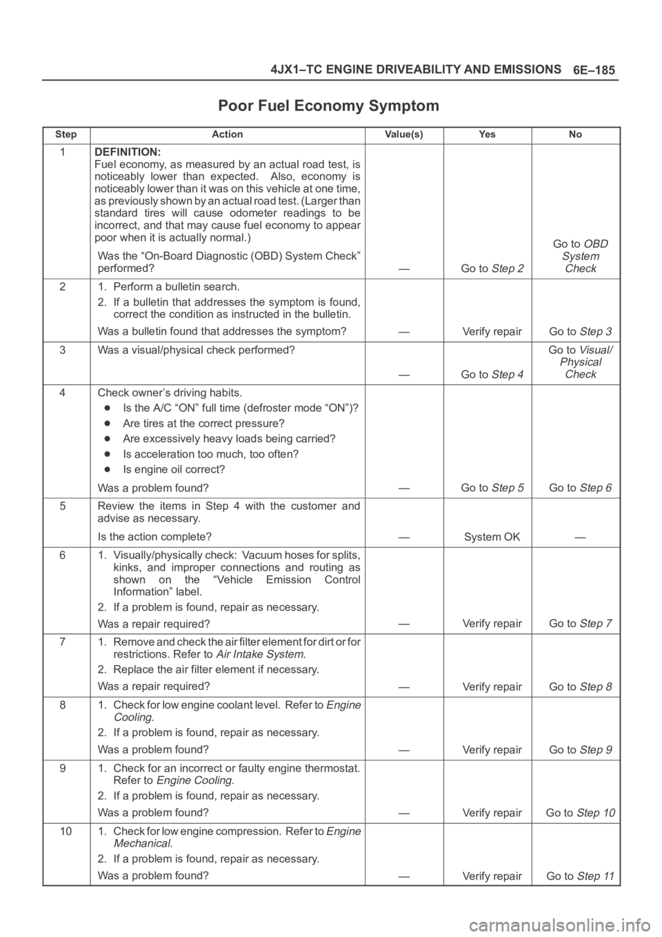
Poor Fuel Economy Symptom
StepActionVa l u e ( s )Ye sNo
1DEFINITION:
Fuel economy, as measured by an actual road test, is
noticeably lower than expected. Also, economy is
noticeably lower than it was on this vehicle at one time,
as previously shown by an actual road test. (Larger than
standard tires will cause odometer readings to be
incorrect, and that may cause fuel economy to appear
poor when it is actually normal.)
Was the “On-Board Diagnostic (OBD) System Check”
performed?
—Go to Step 2
Go to OBD
System
Check
21. Perform a bulletin search.
2. If a bulletin that addresses the symptom is found,
correct the condition as instructed in the bulletin.
Was a bulletin found that addresses the symptom?
—Verify repairGo to Step 3
3Was a visual/physical check performed?
—Go to Step 4
Go to Visual/
Physical
Check
4Check owner’s driving habits.
Is the A/C “ON” full time (defroster mode “ON”)?
Are tires at the correct pressure?
Are excessively heavy loads being carried?
Is acceleration too much, too often?
Is engine oil correct?
Was a problem found?
—Go to Step 5Go to Step 6
5Review the items in Step 4 with the customer and
advise as necessary.
Is the action complete?
—System OK—
61. Visually/physically check: Vacuum hoses for splits,
kinks, and improper connections and routing as
shown on the “Vehicle Emission Control
Information” label.
2. If a problem is found, repair as necessary.
Was a repair required?
—Verify repairGo to Step 7
71. Remove and check the air filter element for dirt or for
restrictions. Refer to
Air Intake System.
2. Replace the air filter element if necessary.
Was a repair required?
—Verify repairGo to Step 8
81. Check for low engine coolant level. Refer to Engine
Cooling
.
2. If a problem is found, repair as necessary.
Was a problem found?
—Verify repairGo to Step 9
91. Check for an incorrect or faulty engine thermostat.
Refer to
Engine Cooling.
2. If a problem is found, repair as necessary.
Was a problem found?
—Verify repairGo to Step 10
101. Check for low engine compression. Refer to Engine
Mechanical
.
2. If a problem is found, repair as necessary.
Was a problem found?
—Verify repairGo to Step 11
Page 2543 of 6000
8A–4LIGHTING SYSTEM
Headlight
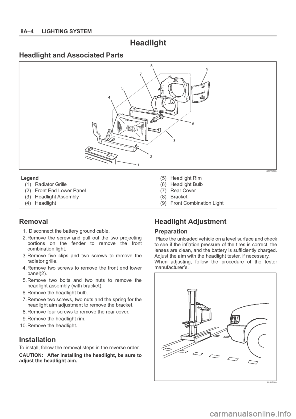
Headlight and Associated Parts
801RW003
Legend
(1) Radiator Grille
(2) Front End Lower Panel
(3) Headlight Assembly
(4) Headlight(5) Headlight Rim
(6) Headlight Bulb
(7) Rear Cover
(8) Bracket
(9) Front Combination Light
Removal
1. Disconnect the battery ground cable.
2. Remove the screw and pull out the two projecting
portions on the fender to remove the front
combination light.
3. Remove five clips and two screws to remove the
radiator grille.
4. Remove two screws to remove the front end lower
panel(2).
5. Remove two bolts and two nuts to remove the
headlight assembly (with bracket).
6. Remove the headlight bulb.
7. Remove two screws, two nuts and the spring for the
headlight aim adjustment to remove the bracket.
8. Remove four screws to remove the rear cover.
9. Remove the headlight rim.
10. Remove the headlight.
Installation
To install, follow the removal steps in the reverse order.
CAUTION: After installing the headlight, be sure to
adjust the headlight aim.
Headlight Adjustment
Preparation
Place the unloaded vehicle on a level surface and check
to see if the inflation pressure of the tires is correct, the
lenses are clean, and the battery is sufficiently charged.
Adjust the aim with the headlight tester, if necessary.
When adjusting, follow the procedure of the tester
manufacturer’s.
801RS009
Page 3449 of 6000
SUPPLEMENTAL RESTRAINT SYSTEM 9J–12
Deployed Air Bag Assembly (Driver Side)
“You should wear gloves and glasses. After the air bag
assembly has been deployed, the surface of the air bag
may contain solid particulate. This solid particulate
c o n s i s t s p r i m a r i l y o f b y p r oducts of the chemical reaction,
Potassium Chloride and copper metal dust. Compounds
of Potassium Borate, Strontium Chloride, Copper
Chloride, and Ammonium Chloride may be found in
amounts of about 1% (each) of the total particulate.”
Deployed Pretensioner Seat Belt.
You should wear gloves and safety glasses. After the
pretensioner seat belt has been deployed, the surface of
the pretensioner seat belt cylinder may heating up.
Air Bag Assembly and/or Pretensioner
Seat Belt Scrapping Procedure.
During the cause of vehicle’s useful life, certain situations
may arise which will necessitate the disposal of a live air
bag and/or pretensioner seat belt. (This information
covers proper procedures for disposing of a live air bag
assembly and/or pretensioner seat belt.)
Before a live air bag assembly can be dispose off, it must
be deployed.
A live air bag assembly and/or pretensioner seat belt
must not be disposed of though normal refuse channels.
WARNING: FAILURE TO FOLLOW PROPER
SUPPLEMENTAL RESTRAINT SYSTEM (SRS) AIR
BAG ASSEMBLY DISPOSAL PROCEDURES CAN
RESULT IN AIR BAG DEPLOYMENT WHICH MAY
CAUSE PERSONAL INJURY. AN UNDPLOYED AIR
BAG ASSEMBLY MUST NOT BE DISPOSED OF
THROUGH NORMAL REFUSE CHANNELS. THE
UNDEPLOYED AIR BAG ASSEMBLY CONTAINS
SUBSTANCES THAT CAN CAUSE SEVERE ILLNESS
OR PERSONAL INJURY IF THE SEALED CONTAINER
IS DAMAGED DURING DISPOSAL. DISPOSAL IN
ANY MANNER INCONSISTENT WITH PROPER
PROCEDURES MAY BE A VIOLATION OF LOCAL
LAW.
In situations which require deployment of a live air bag
assembly, deployment may be accomplished inside or
outside the vehicle. The method employed depends
upon the final disposition of the particular vehicle, as
noted in “Deployment Outside Vehicle” and “Deployment
Inside Vehicle” in this section.
Cautions About Air Bag Deployment And
Disposal
Failure to follow proper procedures could result in
erroneous air bag deployment which may cause personal
injury be sure to follow proper procedures.
1. Turn off (Lock) the ignition switch and disconnect the
minus terminal of the battery, then start the work 15 or
more sec later. (Air bag is designed to work by the
back-up power source even if the battery power
source is cut off at vehicle collision).
2. Be sure not to disassemble the air bag.
3. Do not give an impact to the air bag and bring the air
bag close to magnet. (The air bag could deploy
unexpectedly).4. Place the air bag with its trim cover up.
5. Do not let the air bag deploy directly on the floor. (The
air bag may be blown off 2
3 m (6.5 or 10 feet)).
6. Be sure to install the air bag firmly to a deployment
tool (fixing tool).
7. Set a battery 10 m (33 feet) or more away from the air
bag.
8. Before disconnecting air bag harness, ground the
worker by touching the vehicle outer panel with bare
hand.
9. When connecting or disconnecting the harness, do
not work just in front of the air bag.
10. As deployment gives rise to big sound, warn the
people around against it. Further, try to reduce the
sound by covering the steering wheel or tires, and
shut the vehicle windows in case of deployment
inside the vehicle.
11. As deployment generates smoke, select a well
ventilated place. (In case of deployment indoors,
avoid deployment just under a fire alarm, smoke
sensor, and fluorescent lamps).
12. Be careful not to inhale the smoke after deployment.
13. If part of the vehicle glass is damaged, cover the
vehicle with a car cover to prevent the glass from
braking at the time of deployment.
14. Do not touch the air bag immediately after
deployment, since it remains hot for 30 minutes.
15. Do not water the air bag immediately after
deployment.
16. Wear safety glasses and gloves throughout the work
and wash the glasses and gloves after the work.
17. Do not reuse the removed air bag for another vehicle.
(Deployment characteristic is different with vehicle
types).
Deployment Outside Vehicle (Driver Air
Bag Assembly)
Deployment outside the vehicle is proper when the
vehicle is to be returned to service. This includes, for
example, situations in which the vehicle will be returned to
useful service after a functionally or cosmetically deficient
air bag assembly is replaced. Deployment and disposal
of a malfunctioning air bag assembly is, of course, subject
to any required retention period.
For deployment of a live (undeployed) air bag assembly
outside the vehicle, the deployment procedure must be
followed exactly. Always wear safety glasses during this
deployment procedure until a deployed air bag assembly
is scrapped or until an undeployed air bag assembly is
shipped. Before performing the procedures you should
be familiar with servicing the SRS and with proper
handling of the air bag assembly. Procedures should be
read fully before they are performed.
The following procedure requires use of 5–8840–2468–0
SRS deployment harness with appropriate pigtail
adapter. Do not attempt procedure without
5–8840–2468–0 adapter.
WARNING: FAILURE TO FOLLOW PROCEDURES IN
THE ORDER LISTED MAY RESULT IN PERSONAL
INJURY. NEVER CONNECT DEPLOYMENT
Page 3455 of 6000
SUPPLEMENTAL RESTRAINT SYSTEM 9J–18
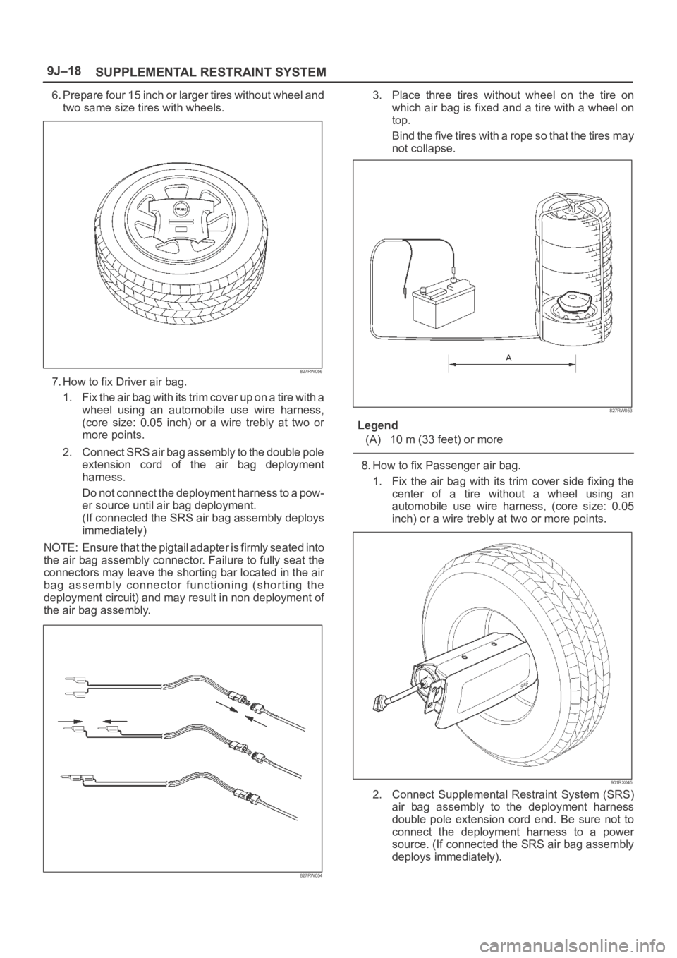
6. Prepare four 15 inch or larger tires without wheel and
two same size tires with wheels.
827RW056
7. How to fix Driver air bag.
1. Fix the air bag with its trim cover up on a tire with a
wheel using an automobile use wire harness,
(core size: 0.05 inch) or a wire trebly at two or
more points.
2. Connect SRS air bag assembly to the double pole
extension cord of the air bag deployment
harness.
Do not connect the deployment harness to a pow-
er source until air bag deployment.
(If connected the SRS air bag assembly deploys
immediately)
NOTE: Ensure that the pigtail adapter is firmly seated into
the air bag assembly connector. Failure to fully seat the
connectors may leave the shorting bar located in the air
bag assembly connector functioning (shorting the
deployment circuit) and may result in non deployment of
the air bag assembly.
827RW054
3. Place three tires without wheel on the tire on
which air bag is fixed and a tire with a wheel on
top.
Bind the five tires with a rope so that the tires may
not collapse.
827RW053
Legend
(A) 10 m (33 feet) or more
8. How to fix Passenger air bag.
1. Fix the air bag with its trim cover side fixing the
center of a tire without a wheel using an
automobile use wire harness, (core size: 0.05
inch) or a wire trebly at two or more points.
901RX045
2. Connect Supplemental Restraint System (SRS)
air bag assembly to the deployment harness
double pole extension cord end. Be sure not to
connect the deployment harness to a power
source. (If connected the SRS air bag assembly
deploys immediately).
Page 3456 of 6000
SUPPLEMENTAL RESTRAINT SYSTEM9J–19
NOTE: Ensure that the pigtail adapter is firmly seated into
the air bag assembly connector. Failure to fully seat the
connectors may leave the shorting bar located in the air
bag assembly connector functioning (shorting the
deployment circuit) and may result in non deployment of
the air bag assembly.
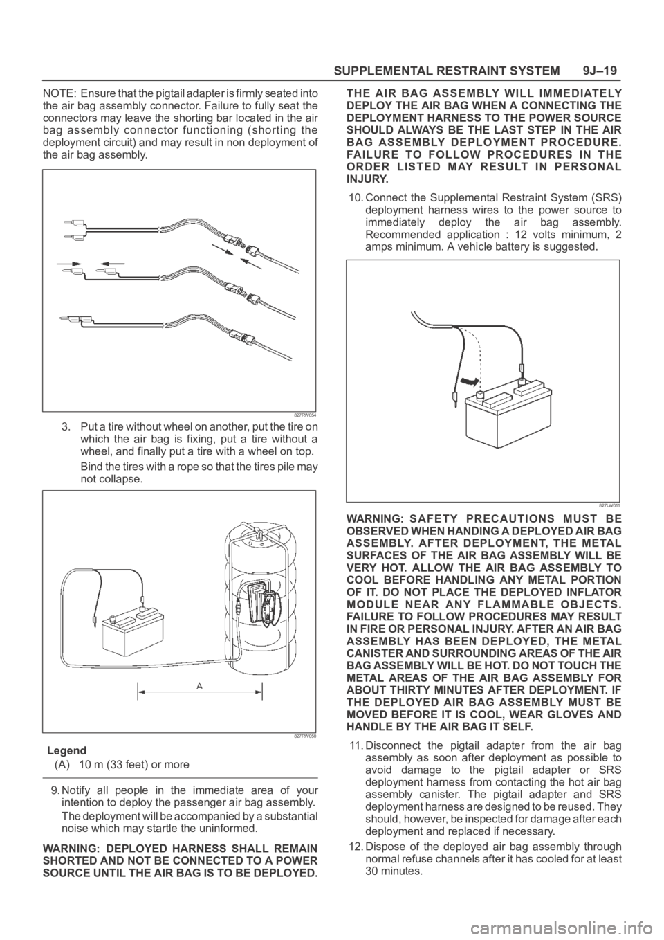
827RW054
3. Put a tire without wheel on another, put the tire on
which the air bag is fixing, put a tire without a
wheel, and finally put a tire with a wheel on top.
Bind the tires with a rope so that the tires pile may
not collapse.
827RW050
Legend
(A) 10 m (33 feet) or more
9. Notify all people in the immediate area of your
intention to deploy the passenger air bag assembly.
The deployment will be accompanied by a substantial
noise which may startle the uninformed.
WARNING: DEPLOYED HARNESS SHALL REMAIN
SHORTED AND NOT BE CONNECTED TO A POWER
SOURCE UNTIL THE AIR BAG IS TO BE DEPLOYED.THE AIR BAG ASSEMBLY WILL IMMEDIATELY
DEPLOY THE AIR BAG WHEN A CONNECTING THE
DEPLOYMENT HARNESS TO THE POWER SOURCE
SHOULD ALWAYS BE THE LAST STEP IN THE AIR
BAG ASSEMBLY DEPLOYMENT PROCEDURE.
FAILURE TO FOLLOW PROCEDURES IN THE
ORDER LISTED MAY RESULT IN PERSONAL
INJURY.
10. Connect the Supplemental Restraint System (SRS)
deployment harness wires to the power source to
immediately deploy the air bag assembly.
Recommended application : 12 volts minimum, 2
amps minimum. A vehicle battery is suggested.
827LW011
WARNING: SAFETY PRECAUTIONS MUST BE
OBSERVED WHEN HANDING A DEPLOYED AIR BAG
ASSEMBLY. AFTER DEPLOYMENT, THE METAL
SURFACES OF THE AIR BAG ASSEMBLY WILL BE
VERY HOT. ALLOW THE AIR BAG ASSEMBLY TO
COOL BEFORE HANDLING ANY METAL PORTION
OF IT. DO NOT PLACE THE DEPLOYED INFLATOR
MODULE NEAR ANY FLAMMABLE OBJECTS.
FAILURE TO FOLLOW PROCEDURES MAY RESULT
I N F IR E O R PE RSO NAL IN JU RY. A FT ER A N A IR BAG
ASSEMBLY HAS BEEN DEPLOYED, THE METAL
CANISTER AND SURROUNDING AREAS OF THE AIR
BAG ASSEMBLY WILL BE HOT. DO NOT TOUCH THE
METAL AREAS OF THE AIR BAG ASSEMBLY FOR
ABOUT THIRTY MINUTES AFTER DEPLOYMENT. IF
THE DEPLOYED AIR BAG ASSEMBLY MUST BE
MOVED BEFORE IT IS COOL, WEAR GLOVES AND
HANDLE BY THE AIR BAG IT SELF.
11. Disconnect the pigtail adapter from the air bag
assembly as soon after deployment as possible to
avoid damage to the pigtail adapter or SRS
deployment harness from contacting the hot air bag
assembly canister. The pigtail adapter and SRS
deployment harness are designed to be reused. They
should, however, be inspected for damage after each
deployment and replaced if necessary.
12. Dispose of the deployed air bag assembly through
normal refuse channels after it has cooled for at least
30 minutes.
Page 3475 of 6000
SUPPLEMENTAL RESTRAINT SYSTEM 9J–38
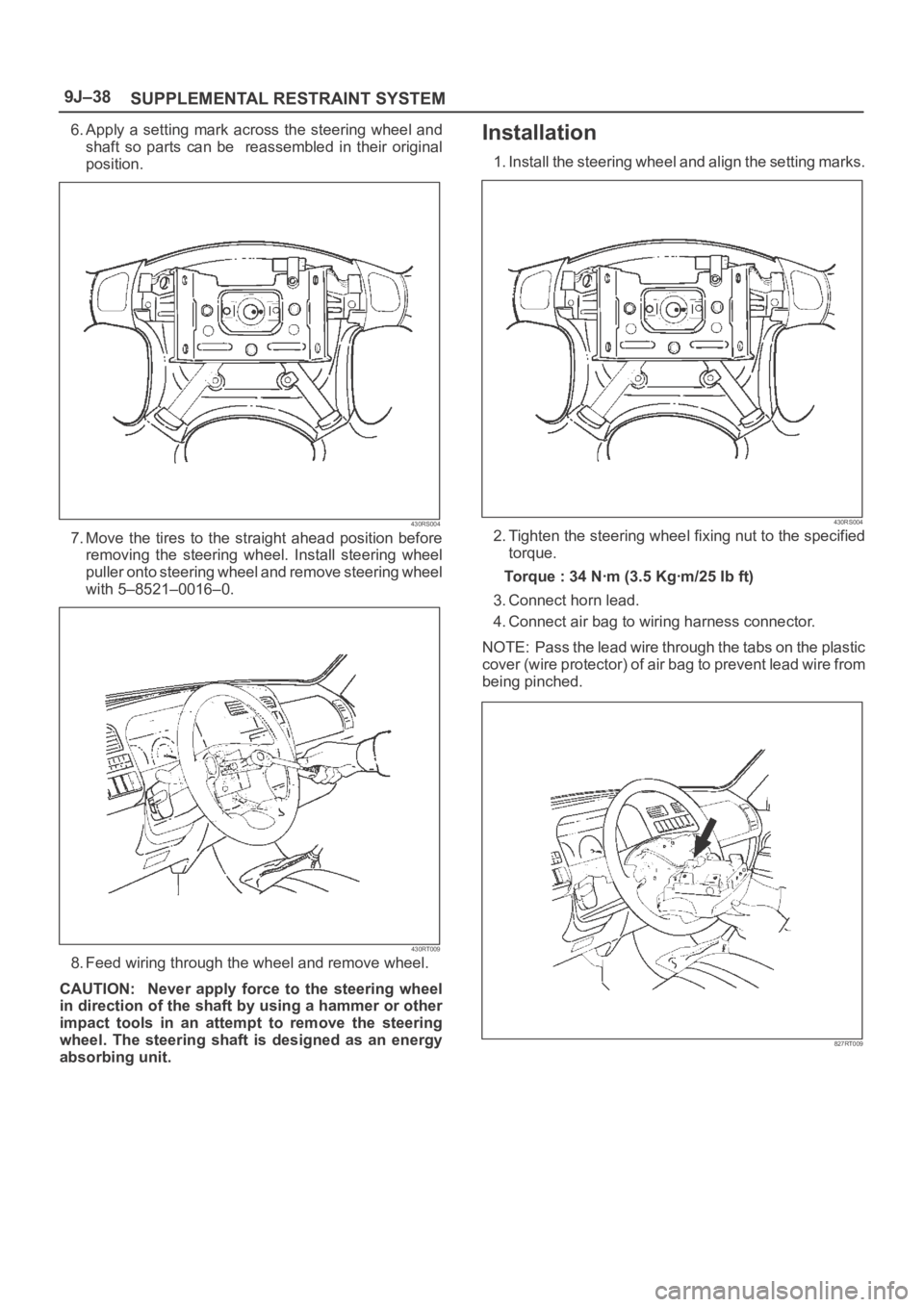
6. Apply a setting mark across the steering wheel and
shaft so parts can be reassembled in their original
position.
430RS004
7. Move the tires to the straight ahead position before
removing the steering wheel. Install steering wheel
puller onto steering wheel and remove steering wheel
with 5–8521–0016–0.
430RT009
8. Feed wiring through the wheel and remove wheel.
CAUTION: Never apply force to the steering wheel
in direction of the shaft by using a hammer or other
impact tools in an attempt to remove the steering
wheel. The steering shaft is designed as an energy
absorbing unit.
Installation
1. Install the steering wheel and align the setting marks.
430RS004
2. Tighten the steering wheel fixing nut to the specified
torque.
Torque : 34 Nꞏm (3.5 Kgꞏm/25 Ib ft)
3. Connect horn lead.
4. Connect air bag to wiring harness connector.
NOTE: Pass the lead wire through the tabs on the plastic
cover (wire protector) of air bag to prevent lead wire from
being pinched.
827RT009
Page 3477 of 6000
SUPPLEMENTAL RESTRAINT SYSTEM 9J–40
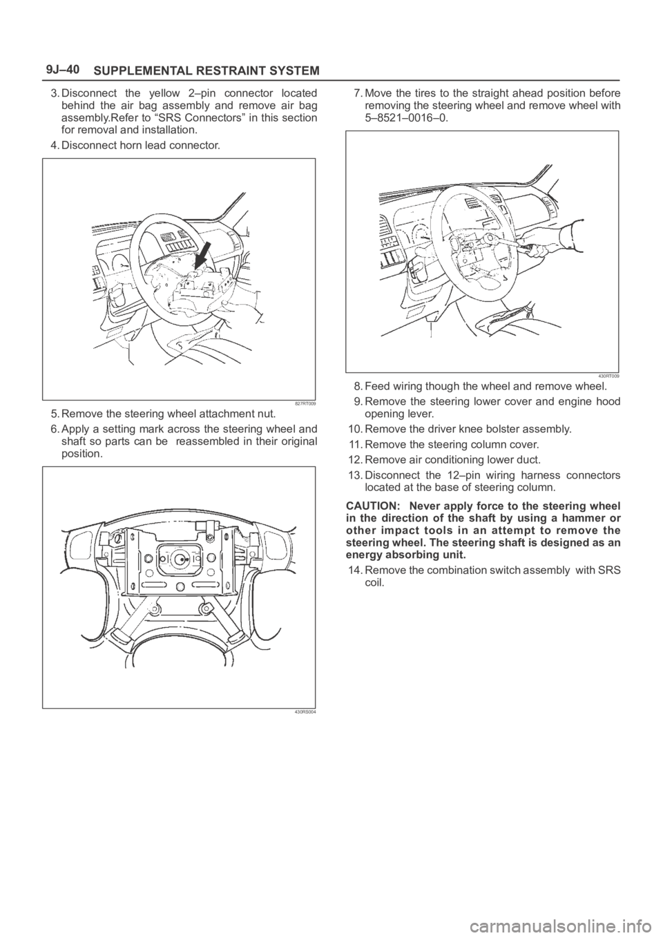
3. Disconnect the yellow 2–pin connector located
behind the air bag assembly and remove air bag
assembly.Refer to “SRS Connectors” in this section
for removal and installation.
4. Disconnect horn lead connector.
827RT009
5. Remove the steering wheel attachment nut.
6. Apply a setting mark across the steering wheel and
shaft so parts can be reassembled in their original
position.
430RS004
7. Move the tires to the straight ahead position before
removing the steering wheel and remove wheel with
5–8521–0016–0.
430RT009
8. Feed wiring though the wheel and remove wheel.
9. Remove the steering lower cover and engine hood
opening lever.
10. Remove the driver knee bolster assembly.
11. Remove the steering column cover.
12. Remove air conditioning lower duct.
13. Disconnect the 12–pin wiring harness connectors
located at the base of steering column.
CAUTION: Never apply force to the steering wheel
in the direction of the shaft by using a hammer or
other impact tools in an attempt to remove the
steering wheel. The steering shaft is designed as an
energy absorbing unit.
14. Remove the combination switch assembly with SRS
coil.
Page 3482 of 6000
SUPPLEMENTAL RESTRAINT SYSTEM9J–45
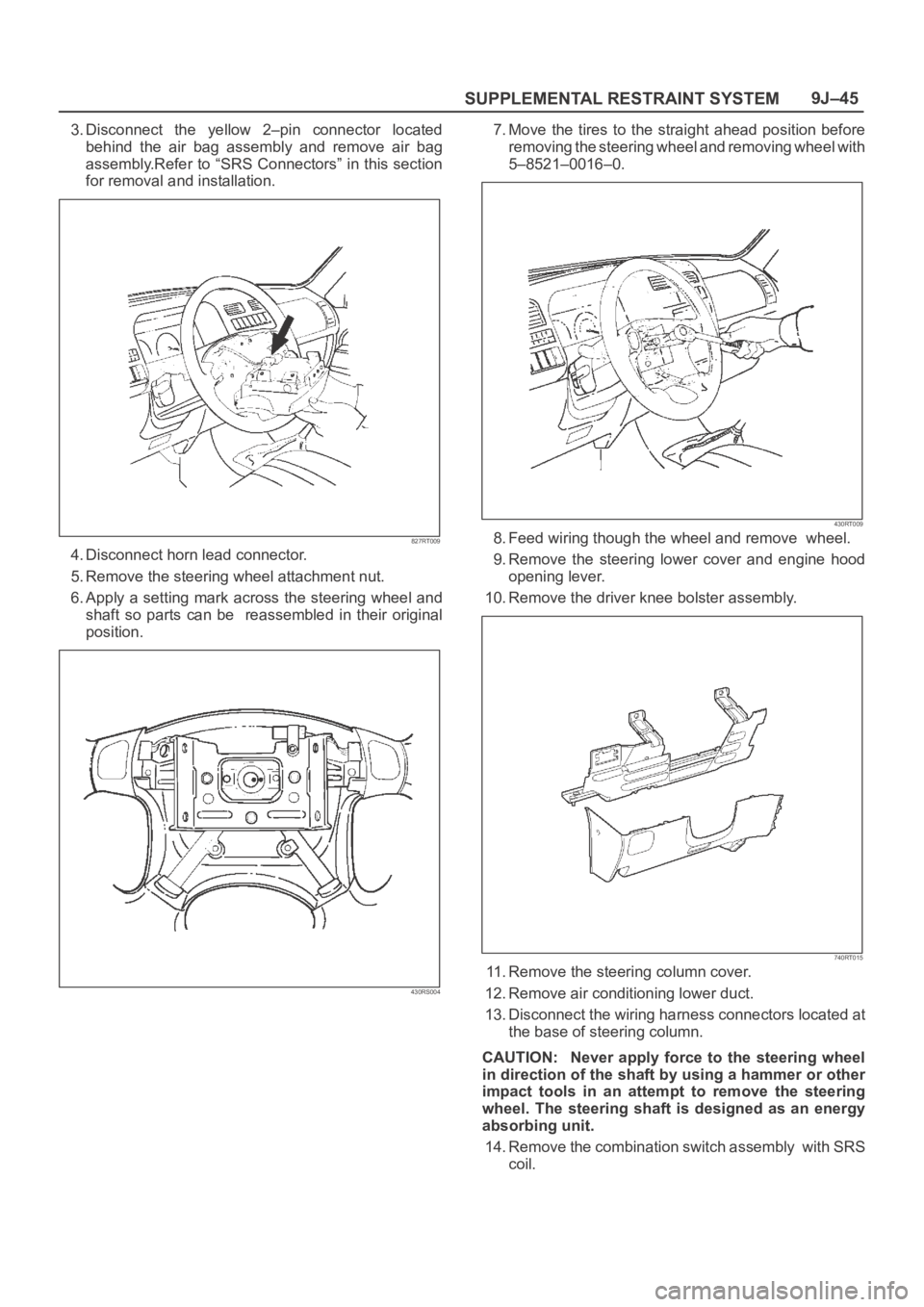
3. Disconnect the yellow 2–pin connector located
behind the air bag assembly and remove air bag
assembly.Refer to “SRS Connectors” in this section
for removal and installation.
827RT009
4. Disconnect horn lead connector.
5. Remove the steering wheel attachment nut.
6. Apply a setting mark across the steering wheel and
shaft so parts can be reassembled in their original
position.
430RS004
7. Move the tires to the straight ahead position before
removing the steering wheel and removing wheel with
5–8521–0016–0.
430RT009
8. Feed wiring though the wheel and remove wheel.
9. Remove the steering lower cover and engine hood
opening lever.
10. Remove the driver knee bolster assembly.
740RT015
11. Remove the steering column cover.
12. Remove air conditioning lower duct.
13. Disconnect the wiring harness connectors located at
the base of steering column.
CAUTION: Never apply force to the steering wheel
in direction of the shaft by using a hammer or other
impact tools in an attempt to remove the steering
wheel. The steering shaft is designed as an energy
absorbing unit.
14. Remove the combination switch assembly with SRS
coil.