1998 OPEL FRONTERA tires
[x] Cancel search: tiresPage 563 of 6000

4B1–30
DRIVE LINE CONTROL SYSTEM (SHIFT ON THE FLY)
Front Axle Diagnosis
When the 4WD switch is operated from 4H to 2H,
indicator light does not go out.
Step
ActionYe sNo
1Drive slow 100 — 200m after a few minutes” idling.
Has indicator light gone out?
All right.Go to Step 2
2Jack up front tires.
Does the right side of front wheel rotate when the left side of f r o n t
wheel is rotated?
Go to Step 4Go to Step 3
31. Check the actuator switch.
2. Check the circuit to indicator.
Was a problem found?
Trace this chart
from the start
after repair or
replace.
Disassemble axle
ASM for check.
Trace this chart
from the start
after repair or
replace.
41. Check the VSV valve.
2. Check the circuit to VSV valve.
Was a problem found?Trace this chart
from the start
after repair or
replace.
Go to Step 5
5I s v a c u u m p i p i n g a l l r i g h t ? ( t a n k , h o s e , & p i p e d a m a g e o r t r o u ble)
Go to Step 6
Trace this chart
from the start
after repair or
replace.
6Does actuator work all right?
Trace this chart
from the start.
Disassemble axle
ASM for check.
Trace this chart
from the start
after repair or
replace.
Page 564 of 6000

4B1–31 DRIVE LINE CONTROL SYSTEM (SHIFT ON THE FLY)
When the 4WD switch is operated from 2H to 4H,
indicator light is not actuated.
Step
ActionYe sNo
1Drive slow 100 — 200m after a few minutes” idling.
Has indicator light actuated?
All right.Go to Step 2
2Jack up front tires.
Does not the right side of front wheel rotate when the left side of
front wheel is rotated?
Go to Step 4Go to Step 3
31. Check the actuator switch.
2. Check the circuit to indicator.
Was a problem found?
Trace this chart
from the start
after repair or
replace.
Disassemble axle
ASM for check.
Trace this chart
from the start
after repair or
replace.
41. Check the VSV valve.
2. Check the circuit to VSV valve.
Was a problem found?Trace this chart
from the start
after repair or
replace.
Go to Step 5
5I s v a c u u m p i p i n g a l l r i g h t ? ( t a n k , h o s e , & p i p e d a m a g e o r t r o u ble)
Go to Step 6
Trace this chart
from the start
after repair or
replace.
6Does actuator work all right?
Trace this chart
from the start.
Disassemble axle
ASM for check.
Trace this chart
from the start
after repair or
replace.
Page 657 of 6000

DRIVE LINE CONTROL SYSTEM (TOD) 4B2–86
Diagnosis from Symptom
Troubles that are not indicated by the warning lamp are
listed in the table below. These troubles are caused by
the faults that cannot be detected by the self-diagnostic
function of the control unit.
If this type of trouble is observed, interview the customer
and conduct test runs to reproduce the trouble,cross-check the reported trouble with the listed
phenomena, and diagnose and analyze the trouble on the
item by item basis.
PhenomenaMajor causeCorrective action
1The tight corner braking is ob-
served when the vehicle is subject
to full steering.The standard tires are not used.
The tire pressure is incorrect.
The tires are worn inuniformity.
The transfer or wiring is
imperfect.
The limited slip differential is
failed.
Check and recondition the ve-
hicle according to Chart 1.
2Even if the 4WD SW is select to the
4WD position, the 4WD mode is not
active, resulting in remarkable rear
wheel spin.The transfer or wiring is
imperfect.
The shift on the fly system is
failed.
Check and recondition the ve-
hicle according to Chart 2.
3When the 4WD SW is select to
the 4WD position, the drive
resistance of the 4WD system is
too large to get sufficient running
speed.
Noised drive line.
The standard tires are not used.
The tire pressure is incorrect.
The tires are worn inuniformity.
The transfer or wiring is
imperfect.
The limited slip differential is
Check and recondition the ve-
hicle according to Chart 1.
4The shift on the fly system (front
axle) generates gear noises.The wiring is imperfect.
The full automatic free wheel
hub is failed.
Check and recondition the ve-
hicle according to Chart 3.
5The braking distance gets long
even when the ABS is active.The wiring is imperfect.
The ABS is failed.
Check and recondition the ve-
hicle according to Chart 4.
Page 659 of 6000

DRIVE LINE CONTROL SYSTEM (TOD) 4B2–88
StepActionYe sNo
1Are the front and rear tires in specified size?
Go to Step 2
Replace the tires
with specified
ones, and service
the new tires.
Go to Step 16
2Is the tire pressure correct?
Go to Step 3
Replace the tires
with specified
ones, and service
the new tires.
Go to Step 16
3Are the tires free from abnormal wear?
Go to Step 4
Replace the tires
with specified
ones, and service
the new tires.
Go to Step 16
4Are different types of tires used?
Go to Step 5
Replace the tires
with specified
ones, and service
the new tires.
Go to Step 16
51. Start the engine.
2. Shift the transfer lever to the high (TOD) position.
3. Fully turn the steering to the left (or right) end, and select the D
range and start the creep run.
Does the tight corner braking occur? Is the judder with chug-chug
sound observed? * Use caution on the operation.
Go to Step 6 Go to Step 11
61. Shift the transfer lever to the 2H position.
2. Fully turn the steering to the left (or right) end, and select the D
range and start the creep run.
Does the tight corner braking occur? Is the judder with chug-chug
sound observed? * Use caution on the operation.
Go to Step 7 Go to Step 14
7Is an LSD mounted to the rear differential? Go to Step 8 Go to Step 9
8Is the genuine LSD oil used in the rear differential?
Go to Step 9
Replace the
differential oil.
Go to Step 16
9Does the engine output the power correctly?
Go to Step 10
Check the
engine.
Go to Step 16
10Do the speed sensors work correctly? (Check trouble codes.)The ECU has
failed. Replace
the ECU.
Go to Step 16
Replace the
speed sensors.
Go to Step 16
11Is the tight corner braking observed only when the brake is
applied?
Go to Step 12
Conduct full
steering under
WOT.
Go to Step 5
121. Turn off the starter switch.
2. Disconnect the ECU connector.
Is the battery voltage observed between terminals (B–68)6 and
(B–67)11?
Go to Step 13
Repair the circuit
of terminal 6
(ABS IN).
Go to Step 16
Page 669 of 6000

4C–3 DRIVE SHAFT SYSTEM
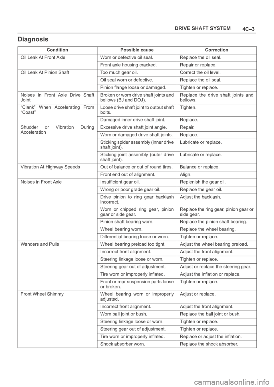
Diagnosis
ConditionPossible causeCorrection
Oil Leak At Front AxleWorn or defective oil seal.Replace the oil seal.
Front axle housing cracked.Repair or replace.
Oil Leak At Pinion ShaftToo much gear oil.Correct the oil level.
Oil seal worn or defective.Replace the oil seal.
Pinion flange loose or damaged.Tighten or replace.
Noises In Front Axle Drive Shaft
JointBroken or worn drive shaft joints and
bellows (BJ and DOJ).Replace the drive shaft joints and
bellows.
“Clank” When Accelerating From
“Coast”Loose drive shaft joint to output shaft
bolts.Tighten.
Damaged inner drive shaft joint.Replace.
Shudder or Vibration During
Acceleration
Excessive drive shaft joint angle.Repair.
AccelerationWorn or damaged drive shaft joints.Replace.
Sticking spider assembly (inner drive
shaft joint).Lubricate or replace.
Sticking joint assembly (outer drive
shaft joint).Lubricate or replace.
Vibration At Highway SpeedsOut of balance or out of round tires.Balance or replace.
Front end out of alignment.Align.
Noises in Front AxleInsufficient gear oil.Replenish the gear oil.
Wrong or poor grade gear oil.Replace the gear oil.
Drive pinion to ring gear backlash
incorrect.Adjust the backlash.
Worn or chipped ring gear, pinion
gear or side gear.Replace the ring gear, pinion gear or
side gear.
Pinion shaft bearing worn.Replace the pinion shaft bearing.
Wheel bearing worn.Replace the wheel bearing.
Differential bearing loose or worn.Tighten or replace.
Wanders and PullsWheel bearing preload too tight.Adjust the wheel bearing preload.
Incorrect front alignment.Adjust the front alignment.
Steering linkage loose or worn.Tighten or replace.
Steering gear out of adjustment.Adjust or replace the steering gear.
Tire worn or improperly inflated.Adjust the inflation or replace.
Front or rear suspension parts loose
or broken.Tighten or replace.
Front Wheel ShimmyWheel bearing worn or improperly
adjusted.Adjust or replace.
Incorrect front alignment.Adjust the front alignment.
Worn ball joint or bush.Replace the ball joint or bush.
Steering linkage loose or worn.Tighten or replace.
Steering gear out of adjustment.Tighten or replace.
Tire worn or improperly inflated.Replace or adjust the inflation.
Shock absorber worn.Replace the shock absorber.
Page 670 of 6000

4C–4
DRIVE SHAFT SYSTEM
Rear Axle Shaft
Rear Axle Shaft and Associated Parts
420RW014
Legend
(1) Brake Caliper
(2) Brake Disc
(3) Wheel Pin
(4) Axle Shaft Assembly
(5) Back Plate
(6) Parking Brake Assembly
(7) Bearing Holder(8) Bearing
(9) Retainer
(10) Snap Ring
(11) Bolt
(12) Nut
(13) Antilock Brake System (ABS) Speed Sensor (if
so equipped)
Removal
1. Raise the vehicle.
2. Remove tires and wheels. Refer to Wheel in Steering
section.3. Remove brake caliper. Use a wire to attach the brake
caliper to the frame. Refer to Disk Brakes in Brake
section.
4. Remove brake disc.
5. Remove ABS sensor (if so equipped).
6. Remove Parking brake assembly. Refer to Parking
Brakes in Brake section.
Page 866 of 6000

5A–56
BRAKE CONTROL SYSTEM
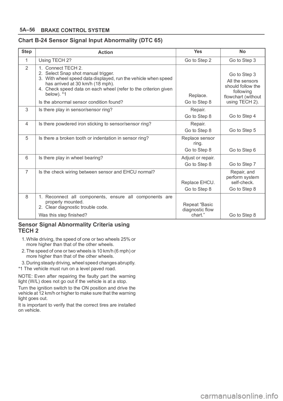
Chart B-24 Sensor Signal Input Abnormality (DTC 65)
StepActionYe sNo
1Using TECH 2?Go to Step 2Go to Step 3
21. Connect TECH 2.
2. Select Snap shot manual trigger.
3. With wheel speed data displayed, run the vehicle when speed
has arrived at 30 km/h (18 mph).
4. Check speed data on each wheel (refer to the criterion given
below). *1
Is the abnormal sensor condition found?
Replace.
Go to Step 8
Go to Step 3
All the sensors
should follow the
following
flowchart (without
using TECH 2).
3Is there play in sensor/sensor ring?Repair.
Go to Step 8
Go to Step 4
4Is there powdered iron sticking to sensor/sensor ring?Repair.
Go to Step 8
Go to Step 5
5Is there a broken tooth or indentation in sensor ring?Replace sensor
ring.
Go to Step 8
Go to Step 6
6Is there play in wheel bearing?Adjust or repair.
Go to Step 8
Go to Step 7
7Is the check wiring between sensor and EHCU normal?
Replace EHCU.
Go to Step 8
Repair, and
perform system
self-check.
Go to Step 8
81. Reconnect all components, ensure all components are
properly mounted.
2. Clear diagnostic trouble code.
Was this step finished?
Repeat “Basic
diagnostic flow
chart.”
Go to Step 8
Sensor Signal Abnormality Criteria using
TECH 2
1. While driving, the speed of one or two wheels 25% or
more higher than that of the other wheels.
2. The speed of one or two wheels is 10 km/h (6 mph) or
more higher than that of the other wheels.
3. During steady driving, wheel speed changes abruptly.
*1 The vehicle must run on a level paved road.
NOTE: Even after repairing the faulty part the warning
light (W/L) does not go out if the vehicle is at a stop.
Turn the ignition switch to the ON position and drive the
vehicle at 12 km/h or higher to make sure that the warning
light goes out.
It is important to verify that the correct tires are installed
on vehicle.
Page 1392 of 6000

6E–275 ENGINE DRIVEABILITY AND EMISSIONS
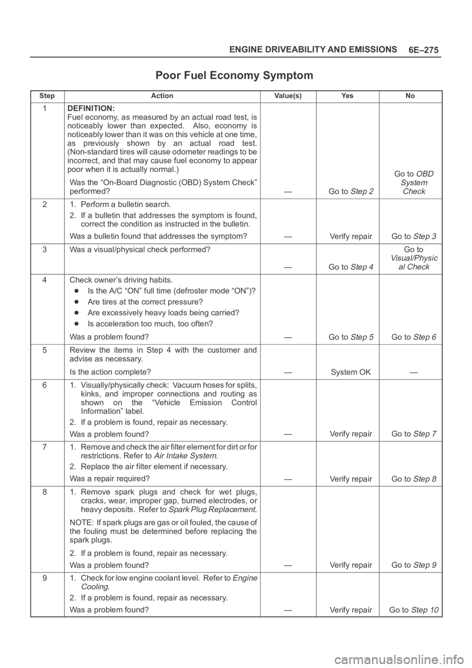
Poor Fuel Economy Symptom
StepActionVa l u e ( s )Ye sNo
1DEFINITION:
Fuel economy, as measured by an actual road test, is
noticeably lower than expected. Also, economy is
noticeably lower than it was on this vehicle at one time,
as previously shown by an actual road test.
(Non-standard tires will cause odometer readings to be
incorrect, and that may cause fuel economy to appear
poor when it is actually normal.)
Was the “On-Board Diagnostic (OBD) System Check”
performed?
—Go to Step 2
Go to OBD
System
Check
21. Perform a bulletin search.
2. If a bulletin that addresses the symptom is found,
correct the condition as instructed in the bulletin.
Was a bulletin found that addresses the symptom?
—Verify repairGo to Step 3
3Was a visual/physical check performed?
—Go to Step 4
Go to
Visual/Physic
al Check
4Check owner’s driving habits.
Is the A/C “ON” full time (defroster mode “ON”)?
Are tires at the correct pressure?
Are excessively heavy loads being carried?
Is acceleration too much, too often?
Was a problem found?
—Go to Step 5Go to Step 6
5Review the items in Step 4 with the customer and
advise as necessary.
Is the action complete?
—System OK—
61. Visually/physically check: Vacuum hoses for splits,
kinks, and improper connections and routing as
shown on the “Vehicle Emission Control
Information” label.
2. If a problem is found, repair as necessary.
Was a problem found?
—Verify repairGo to Step 7
71. Remove and check the air filter element for dirt or for
restrictions. Refer to
Air Intake System.
2. Replace the air filter element if necessary.
Was a repair required?
—Verify repairGo to Step 8
81. Remove spark plugs and check for wet plugs,
cracks, wear, improper gap, burned electrodes, or
heavy deposits. Refer to
Spark Plug Replacement.
NOTE: If spark plugs are gas or oil fouled, the cause of
the fouling must be determined before replacing the
spark plugs.
2. If a problem is found, repair as necessary.
Was a problem found?
—Verify repairGo to Step 9
91. Check for low engine coolant level. Refer to Engine
Cooling
.
2. If a problem is found, repair as necessary.
Was a problem found?
—Verify repairGo to Step 10