1998 OPEL FRONTERA key
[x] Cancel search: keyPage 863 of 6000

5A–53 BRAKE CONTROL SYSTEM
Chart B-21 FR Speed Sensor Short Circuit (DTC 62)
StepActionYe sNo
11. Turn the key off.
2. Disconnect EHCU connector.
3. Measure the FR speed sensor resistance between EHCU
connector terminals 4 and 5.
Is the resistance between 1.3k and 1.9k ohms?
Go to Step 2Go to Step 3
2Is there play in the sensor/sensor rotor?
Go to Step 4
Repair.
Go to Step 6
3Measure the FR speed sensor resistance at the sensor
connector.
Is the resistance between 1.3k and 1.9k ohms?Repair harness
abnormality
between sensors
and EHCU.
Go to Step 6
Replace sensor.
Go to Step 6
4Damage and powdered iron sticking to sensor/sensor ring?
Go to Step 5
Repair.
Go to Step 6
5Is sensor output normal? (Chart C-1-2 or TC-1)Check for faults
in harness
between speed
sensor and
EHCU.
Fault found:
repair, and
perform system
self-check.
No fault found:
replace EHCU.
Go to Step 6
Replace sensor.
Go to Step 6
61. Reconnect all components and ensure all components are
properly mounted.
2. Clear diagnostic trouble code.
Was this step finished?
Repeat “Basic
diagnostic flow
chart.”
Go to Step 6
NOTE: Even after repairing the faulty part the warning
light (W/L) does not go out if the vehicle is at a stop. Turn
the ignition switch to the ON position and drive the vehicle
at 12 km/h or higher to make sure that the warning light
goes out.
Page 864 of 6000

5A–54
BRAKE CONTROL SYSTEM
Chart B-22 RL Speed Sensor Short Circuit (DTC 63)
StepActionYe sNo
11. Turn the key off.
2. Disconnect EHCU connector
3. Measure the RL speed sensor resistance between EHCU
connector terminals 22 and 23.
Is the resistance between 1.3k and 1.9k ohms?
Go to Step 2Go to Step 3
2Is there play in the sensor/sensor rotor?
Go to Step 4
Repair.
Go to Step 6
3Measure the RL speed sensor resistance at the sensor
connector.
Is the resistance between 1.3k and 1.9k ohms?Repair harness
abnormality
between sensors
and EHCU.
Go to Step 6
Replace sensor.
Go to Step 6
4Damage and powdered iron sticking to sensor/sensor ring?
Go to Step 5
Repair.
Go to Step 6
5Is sensor output normal? (Chart C-1-3 or TC-1)?Check for faults
in harness
between speed
sensor and
EHCU.
Fault found:
repair, and
perform system
self-check.
No fault found:
replace EHCU.
Go to Step 6
Replace sensor.
Go to Step 6
61. Reconnect all components and ensure all components are
properly mounted.
2. Clear diagnostic trouble code.
Was this step finished?
Repeat the “Basic
diagnostic flow
chart.”
Go to Step 6
NOTE: Even after repairing the faulty part the warning
light (W/L) does not go out if the vehicle is at a stop. Turn
the ignition switch to the ON position and drive the vehicle
at 12 km/h or higher to make sure that the warning light
goes out.
Page 865 of 6000
5A–55 BRAKE CONTROL SYSTEM
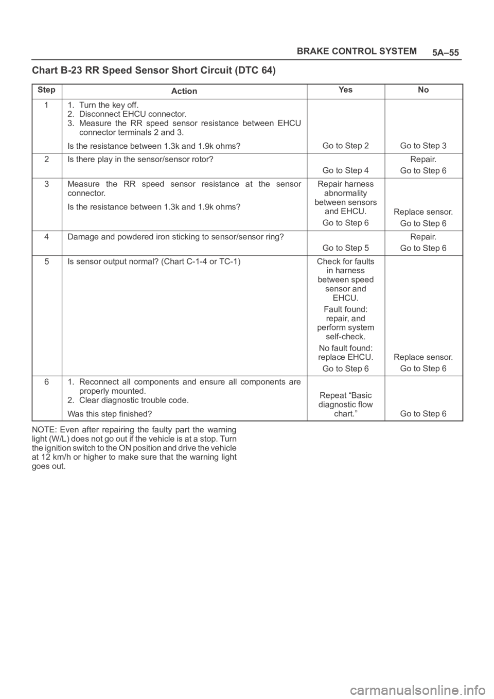
Chart B-23 RR Speed Sensor Short Circuit (DTC 64)
StepActionYe sNo
11. Turn the key off.
2. Disconnect EHCU connector.
3. Measure the RR speed sensor resistance between EHCU
connector terminals 2 and 3.
Is the resistance between 1.3k and 1.9k ohms?
Go to Step 2Go to Step 3
2Is there play in the sensor/sensor rotor?
Go to Step 4
Repair.
Go to Step 6
3Measure the RR speed sensor resistance at the sensor
connector.
Is the resistance between 1.3k and 1.9k ohms?Repair harness
abnormality
between sensors
and EHCU.
Go to Step 6
Replace sensor.
Go to Step 6
4Damage and powdered iron sticking to sensor/sensor ring?
Go to Step 5
Repair.
Go to Step 6
5Is sensor output normal? (Chart C-1-4 or TC-1)Check for faults
in harness
between speed
sensor and
EHCU.
Fault found:
repair, and
perform system
self-check.
No fault found:
replace EHCU.
Go to Step 6
Replace sensor.
Go to Step 6
61. Reconnect all components and ensure all components are
properly mounted.
2. Clear diagnostic trouble code.
Was this step finished?
Repeat “Basic
diagnostic flow
chart.”
Go to Step 6
NOTE: Even after repairing the faulty part the warning
light (W/L) does not go out if the vehicle is at a stop. Turn
the ignition switch to the ON position and drive the vehicle
at 12 km/h or higher to make sure that the warning light
goes out.
Page 867 of 6000
5A–57 BRAKE CONTROL SYSTEM
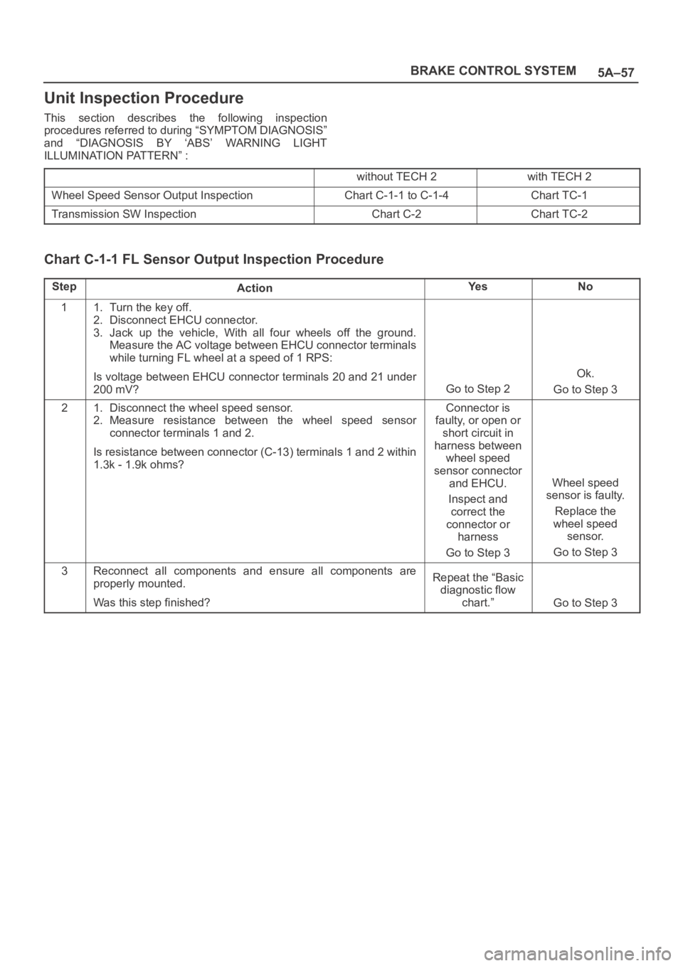
Unit Inspection Procedure
This section describes the following inspection
procedures referred to during “SYMPTOM DIAGNOSIS”
and “DIAGNOSIS BY ‘ABS’ WARNING LIGHT
ILLUMINATION PATTERN” :
without TECH 2with TECH 2
Wheel Speed Sensor Output InspectionChart C-1-1 to C-1-4Chart TC-1
Transmission SW InspectionChart C-2Chart TC-2
Chart C-1-1 FL Sensor Output Inspection Procedure
StepActionYe sNo
11. Turn the key off.
2. Disconnect EHCU connector.
3. Jack up the vehicle, With all four wheels off the ground.
Measure the AC voltage between EHCU connector terminals
while turning FL wheel at a speed of 1 RPS:
Is voltage between EHCU connector terminals 20 and 21 under
200 mV?
Go to Step 2
Ok.
Go to Step 3
21. Disconnect the wheel speed sensor.
2. Measure resistance between the wheel speed sensor
connector terminals 1 and 2.
Is resistance between connector (C-13) terminals 1 and 2 within
1.3k - 1.9k ohms?Connector is
faulty, or open or
short circuit in
harness between
wheel speed
sensor connector
and EHCU.
Inspect and
correct the
connector or
harness
Go to Step 3
Wheel speed
sensor is faulty.
Replace the
wheel speed
sensor.
Go to Step 3
3Reconnect all components and ensure all components are
properly mounted.
Was this step finished?Repeat the “Basic
diagnostic flow
chart.”
Go to Step 3
Page 868 of 6000
5A–58
BRAKE CONTROL SYSTEM
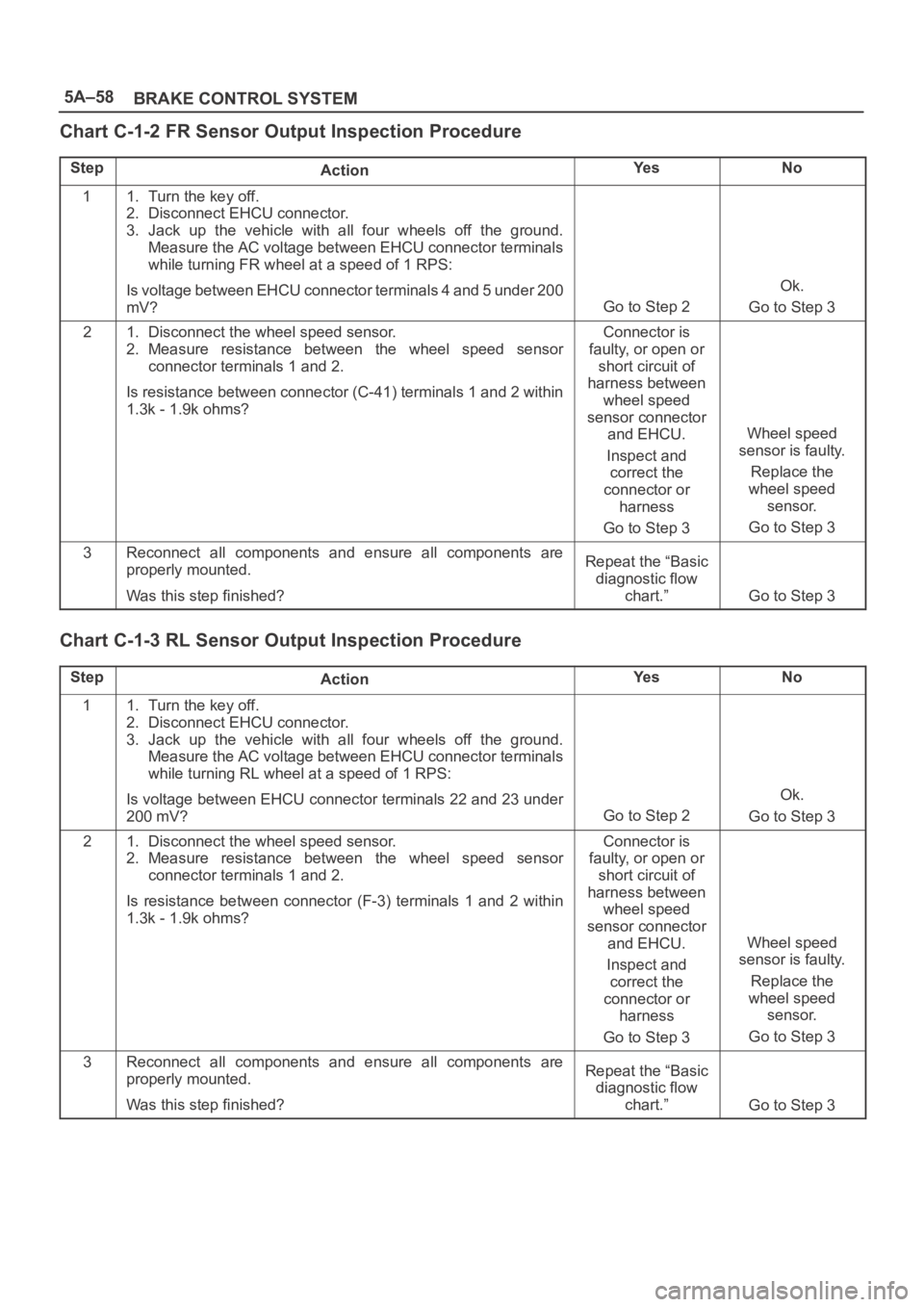
Chart C-1-2 FR Sensor Output Inspection Procedure
StepActionYe sNo
11. Turn the key off.
2. Disconnect EHCU connector.
3. Jack up the vehicle with all four wheels off the ground.
Measure the AC voltage between EHCU connector terminals
while turning FR wheel at a speed of 1 RPS:
Is voltage between EHCU connector terminals 4 and 5 under 200
mV?
Go to Step 2
Ok.
Go to Step 3
21. Disconnect the wheel speed sensor.
2. Measure resistance between the wheel speed sensor
connector terminals 1 and 2.
Is resistance between connector (C-41) terminals 1 and 2 within
1.3k - 1.9k ohms?Connector is
faulty, or open or
short circuit of
harness between
wheel speed
sensor connector
and EHCU.
Inspect and
correct the
connector or
harness
Go to Step 3
Wheel speed
sensor is faulty.
Replace the
wheel speed
sensor.
Go to Step 3
3Reconnect all components and ensure all components are
properly mounted.
Was this step finished?Repeat the “Basic
diagnostic flow
chart.”
Go to Step 3
Chart C-1-3 RL Sensor Output Inspection Procedure
StepActionYe sNo
11. Turn the key off.
2. Disconnect EHCU connector.
3. Jack up the vehicle with all four wheels off the ground.
Measure the AC voltage between EHCU connector terminals
while turning RL wheel at a speed of 1 RPS:
Is voltage between EHCU connector terminals 22 and 23 under
200 mV?
Go to Step 2
Ok.
Go to Step 3
21. Disconnect the wheel speed sensor.
2. Measure resistance between the wheel speed sensor
connector terminals 1 and 2.
Is resistance between connector (F-3) terminals 1 and 2 within
1.3k - 1.9k ohms?Connector is
faulty, or open or
short circuit of
harness between
wheel speed
sensor connector
and EHCU.
Inspect and
correct the
connector or
harness
Go to Step 3
Wheel speed
sensor is faulty.
Replace the
wheel speed
sensor.
Go to Step 3
3Reconnect all components and ensure all components are
properly mounted.
Was this step finished?Repeat the “Basic
diagnostic flow
chart.”
Go to Step 3
Page 869 of 6000
5A–59 BRAKE CONTROL SYSTEM
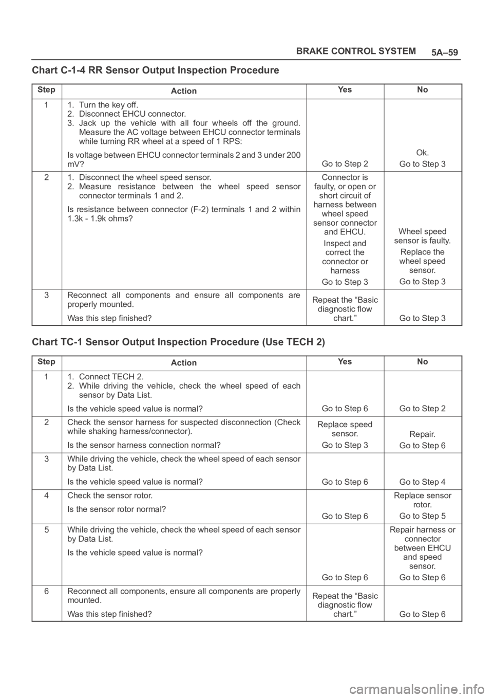
Chart C-1-4 RR Sensor Output Inspection Procedure
StepActionYe sNo
11. Turn the key off.
2. Disconnect EHCU connector.
3. Jack up the vehicle with all four wheels off the ground.
Measure the AC voltage between EHCU connector terminals
while turning RR wheel at a speed of 1 RPS:
Is voltage between EHCU connector terminals 2 and 3 under 200
mV?
Go to Step 2
Ok.
Go to Step 3
21. Disconnect the wheel speed sensor.
2. Measure resistance between the wheel speed sensor
connector terminals 1 and 2.
Is resistance between connector (F-2) terminals 1 and 2 within
1.3k - 1.9k ohms?Connector is
faulty, or open or
short circuit of
harness between
wheel speed
sensor connector
and EHCU.
Inspect and
correct the
connector or
harness
Go to Step 3
Wheel speed
sensor is faulty.
Replace the
wheel speed
sensor.
Go to Step 3
3Reconnect all components and ensure all components are
properly mounted.
Was this step finished?Repeat the “Basic
diagnostic flow
chart.”
Go to Step 3
Chart TC-1 Sensor Output Inspection Procedure (Use TECH 2)
StepActionYe sNo
11. Connect TECH 2.
2. While driving the vehicle, check the wheel speed of each
sensor by Data List.
Is the vehicle speed value is normal?
Go to Step 6Go to Step 2
2Check the sensor harness for suspected disconnection (Check
while shaking harness/connector).
Is the sensor harness connection normal?Replace speed
sensor.
Go to Step 3
Repair.
Go to Step 6
3While driving the vehicle, check the wheel speed of each sensor
by Data List.
Is the vehicle speed value is normal?
Go to Step 6Go to Step 4
4Check the sensor rotor.
Is the sensor rotor normal?
Go to Step 6
Replace sensor
rotor.
Go to Step 5
5While driving the vehicle, check the wheel speed of each sensor
by Data List.
Is the vehicle speed value is normal?
Go to Step 6
Repair harness or
connector
between EHCU
and speed
sensor.
Go to Step 6
6Reconnect all components, ensure all components are properly
mounted.
Was this step finished?Repeat the “Basic
diagnostic flow
chart.”
Go to Step 6
Page 870 of 6000
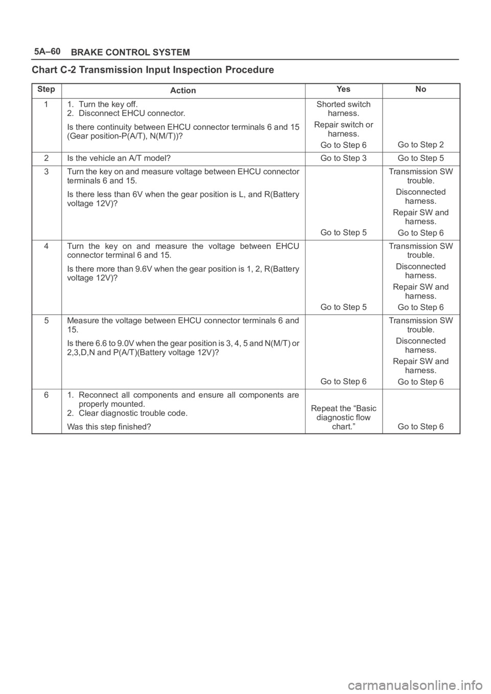
5A–60
BRAKE CONTROL SYSTEM
Chart C-2 Transmission Input Inspection Procedure
StepActionYe sNo
11. Turn the key off.
2. Disconnect EHCU connector.
Is there continuity between EHCU connector terminals 6 and 15
(Gear position-P(A/T), N(M/T))?Shorted switch
harness.
Repair switch or
harness.
Go to Step 6
Go to Step 2
2Is the vehicle an A/T model?Go to Step 3Go to Step 5
3Turn the key on and measure voltage between EHCU connector
terminals 6 and 15.
Is there less than 6V when the gear position is L, and R(Battery
voltage 12V)?
Go to Step 5
Transmission SW
trouble.
Disconnected
harness.
Repair SW and
harness.
Go to Step 6
4Turn the key on and measure the voltage between EHCU
connector terminal 6 and 15.
Is there more than 9.6V when the gear position is 1, 2, R(Battery
voltage 12V)?
Go to Step 5
Transmission SW
trouble.
Disconnected
harness.
Repair SW and
harness.
Go to Step 6
5Measure the voltage between EHCU connector terminals 6 and
15.
Is there 6.6 to 9.0V when the gear position is 3, 4, 5 and N(M/T) or
2,3,D,N and P(A/T)(Battery voltage 12V)?
Go to Step 6
Transmission SW
trouble.
Disconnected
harness.
Repair SW and
harness.
Go to Step 6
61. Reconnect all components and ensure all components are
properly mounted.
2. Clear diagnostic trouble code.
Was this step finished?
Repeat the “Basic
diagnostic flow
chart.”
Go to Step 6
Page 1077 of 6000
6C–10
ENGINE FUEL
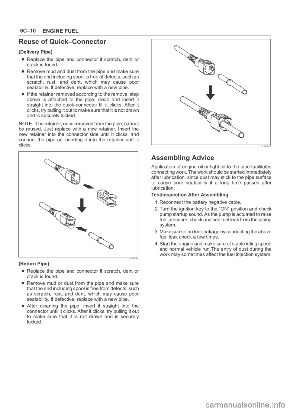
Reuse of Quick–Connector
(Delivery Pipe)
Replace the pipe and connector if scratch, dent or
crack is found.
Remove mud and dust from the pipe and make sure
that the end including spool is free of defects, such as
scratch, rust, and dent, which may cause poor
sealability. If defective, replace with a new pipe.
If the retainer removed according to the removal step
above is attached to the pipe, clean and insert it
straight into the quick-connector till it clicks. After it
clicks, try pulling it out to make sure that it is not drawn
and is securely locked.
NOTE: The retainer, once removed from the pipe, cannot
be reused. Just replace with a new retainer. Insert the
new retainer into the connector side until it clicks, and
connect the pipe as inserting it into the retainer until it
clicks.
141RW018
(Return Pipe)
Replace the pipe and connector if scratch, dent or
crack is found.
Remove mud or dust from the pipe and make sure
that the end including spool is free from defects, such
as scratch, rust, and dent, which may cause poor
sealability. If defective, replace with a new pipe.
After cleaning the pipe, insert it straight into the
connector until it clicks. After it clicks, try pulling it out
to make sure that it is not drawn and is securely
locked.
141RW017
Assembling Advice
Application of engine oil or light oil to the pipe facilitates
connecting work. The work should be started immediately
after lubrication, since dust may stick to the pipe surface
to cause poor sealability if a long time passes after
lubrication.
Test/Inspection After Assembling
1. Reconnect the battery negative cable.
2. Turn the ignition key to the “ON” position and check
pump startup sound. As the pump is actuated to raise
fuel pressure, check and see fuel leak from the piping
system.
3. Make sure of no fuel leakage by conducting the above
fuel leak check a few times.
4. Start the engine and make sure of stable idling speed
and normal vehicle run.The entry of dust during the
work may sometimes affect the fuel injection system.