1998 OPEL FRONTERA key
[x] Cancel search: keyPage 1815 of 6000

6A – 82 ENGINE MECHANICAL
2) Apply liquid gasket (TB1207B or equivalent)
between the cylinder block and the crankcase
fitting surfaces.
3) Install the timing gear case to the cylinder body.
4) Tighten the timing gear case bolt together with
the timing gear case gasket to the specified
torque.
Torque: 20 Nꞏm (2.0 kgꞏm/14.5 lbꞏft)
12. Crankshaft Gear
1) Set key to crankshaft key groove.
2) The timing mark on the crankshaft gear must be
facing outward.
3) Use the crankshaft gear installer to install the
crankshaft gear.
Crankshaft installer: 9-8522-0021-0
Legend
(1) Crankshaft Gear Installer
(2) Crankshaft Gear13. Installation of the Timing Gear
1) Align teeth on the scissors gear and lock them
before install timing gear.
2) Align timing marks on each timing gear and
assemble them.
3) Refer to timing gear detail in this manual.
14. Timing Gear Case Cover
1) Remove lock bolt from idle gear A and remove
lock pin from idle gear C.
2) Install oil pump gear oil seal before assembling
timing gear case cover.
3) Clean fitting surface and apply liquid gasket
(TB1207C or equivalent) to fitting surface.
4) Tighten bolts to specified torque.
Torque: 20 Nꞏm (2.0 kgꞏm/14.5 lb ft)
12
2
012RW066
2
2~2.5mm
2~2.5mm
Apply liquid gasket around inside
of the bolt hole
Bolt hole
Inside
Outside
F06HX00001
012RW024
012RW064
Page 1829 of 6000
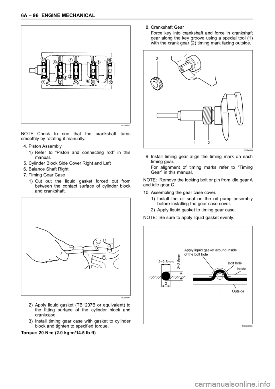
6A – 96 ENGINE MECHANICAL
NOTE: Check to see that the crankshaft turns
smoothly by rotating it manually.
4. Piston Assembly
1) Refer to “Piston and connecting rod” in this
manual.
5. Cylinder Block Side Cover Right and Left
6. Balance Shaft Right.
7. Timing Gear Case
1) Cut out the liquid gasket forced out from
between the contact surface of cylinder block
and crankshaft.
2) Apply liquid gasket (TB1207B or equivalent) to
the fitting surface of the cylinder block and
crankcase.
3) Install timing gear case with gasket to cylinder
block and tighten to specified torque.
Torque: 20 Nꞏm (2.0 kgꞏm/14.5 lb ft)8. Crankshaft Gear
Force key into crankshaft and force in crankshaft
gear along the key groove using a special tool (1)
with the crank gear (2) timing mark facing outside.
9. Install timing gear align the timing mark on each
timing gear.
For alignment of timing marks refer to “Timing
Gear” in this manual.
NOTE: Remove the locking bolt or pin from idle gear A
and idle gear C.
10. Assembling the gear case cover.
1) Install the oil seal on the oil pump assembly
before installing the gear case cover.
2) Apply liquid gasket to timing gear case.
NOTE: Be sure to apply liquid gasket evenly.
84159
610
237
012RW027
012RW064
12
2
012RW066
2
2~2.5mm
2~2.5mm
Apply liquid gasket around inside
of the bolt hole
Bolt hole
Inside
Outside
F06HX00001
Page 1873 of 6000
6D – 6 ENGINE ELECTRICAL
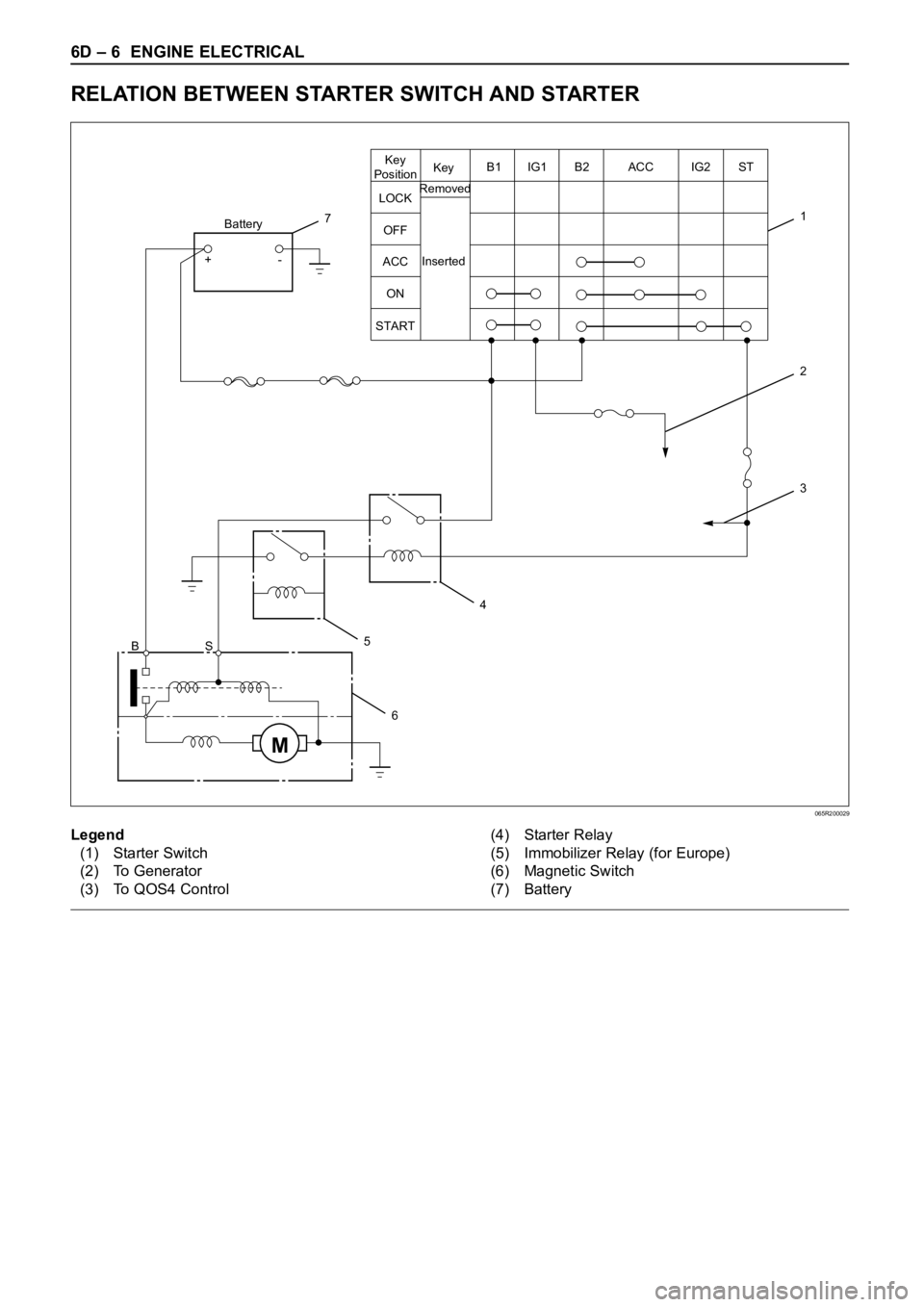
RELATION BETWEEN STARTER SWITCH AND STARTER
M
Key
PositionB1 B2 ACCIG1 IG2 ST
LOCKKey
Removed
Inserted OFF
ACC
ON
START
BSBattery
+-
2
17
3
4
5
6
Legend
(1) Starter Switch
(2) To Generator
(3) To QOS4 Control(4) Starter Relay
(5) Immobilizer Relay (for Europe)
(6) Magnetic Switch
(7) Battery
065R200029
Page 1890 of 6000

ENGINE ELECTRICAL 6D – 23
QOS4 PREHEATING SYSTEM
GENERAL DESCRIPTION
QOS4 preheating system features a quick-on glow plug
with thermometer control of the glowing time and the
afterglow time function.
The system consists of the ECM, indicator lamp, ECT
sensor, vehicle speed sensor, relay and temperature
self-control type glow plugs.With the employment of the ECT sensor, the glow time
changes according to the engine coolant temperature,
thus allowing optimum starting conditions to be
obtained.
The after glow time function is controlled by ECM.
NOTE:
Refer to DTC P0380 and P0381 of 6E section.
SYSTEM DIAGRAM
+
-KEY
50A
ECM
50A
GLOW
50A
2
WHT/
RED
0.5
BLK/
BLU
ECM J1-15 3
WHT/
RED
3
RED/
BLKMAIN
80A
8BLK/RED
Glow
Relay
GLOW PLUG 4
BATTHeater & A/C
Relay
060RW132
Page 1921 of 6000
6E–28
4JX1–TC ENGINE DRIVEABILITY AND EMISSIONS
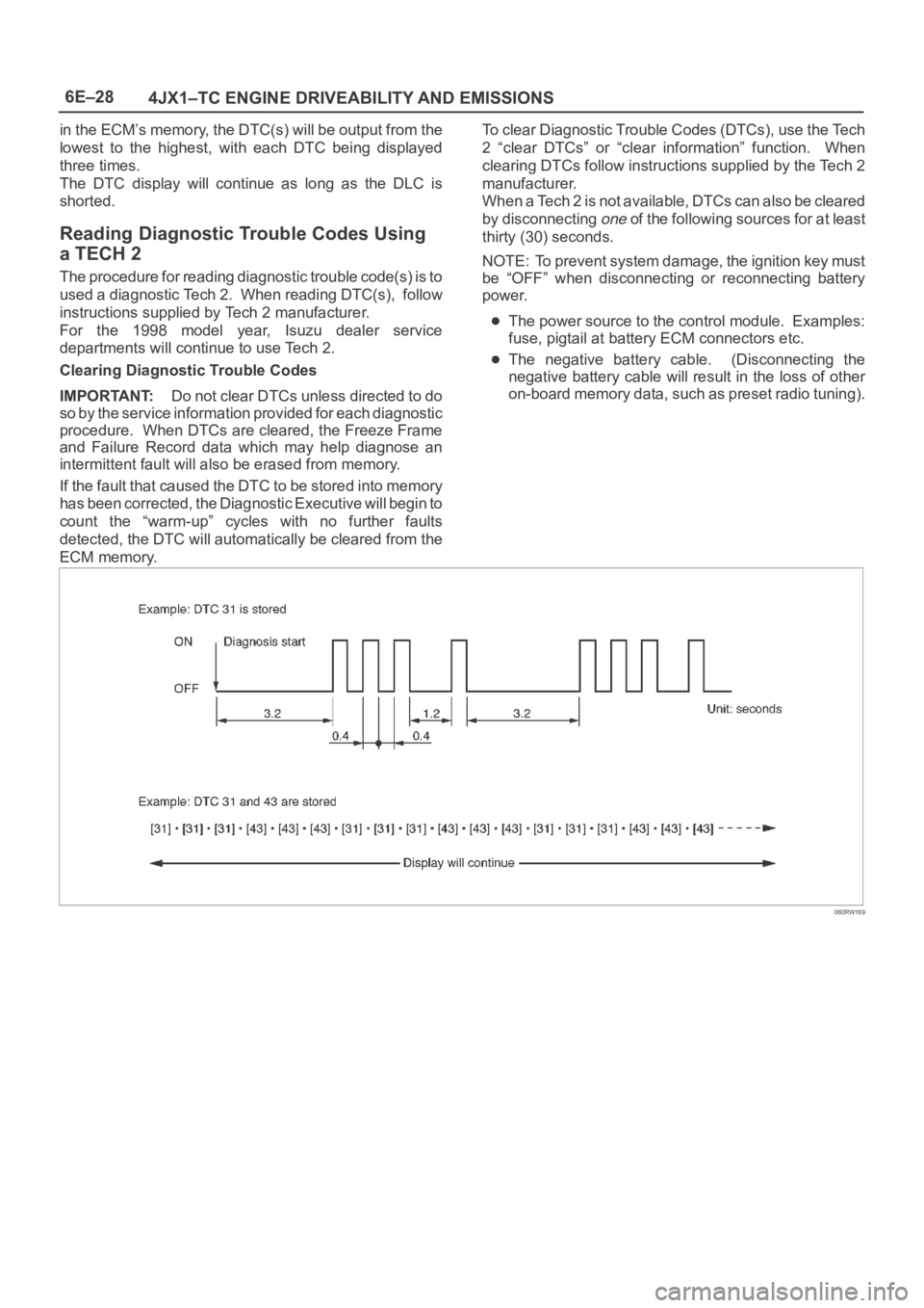
in the ECM’s memory, the DTC(s) will be output from the
lowest to the highest, with each DTC being displayed
three times.
The DTC display will continue as long as the DLC is
shorted.
Reading Diagnostic Trouble Codes Using
a TECH 2
The procedure for reading diagnostic trouble code(s) is to
used a diagnostic Tech 2. When reading DTC(s), follow
instructions supplied by Tech 2 manufacturer.
For the 1998 model year, Isuzu dealer service
departments will continue to use Tech 2.
Clearing Diagnostic Trouble Codes
IMPORTANT:Do not clear DTCs unless directed to do
so by the service information provided for each diagnostic
procedure. When DTCs are cleared, the Freeze Frame
and Failure Record data which may help diagnose an
intermittent fault will also be erased from memory.
If the fault that caused the DTC to be stored into memory
has been corrected, the Diagnostic Executive will begin to
count the “warm-up” cycles with no further faults
detected, the DTC will automatically be cleared from the
ECM memory.To clear Diagnostic Trouble Codes (DTCs), use the Tech
2 “clear DTCs” or “clear information” function. When
clearing DTCs follow instructions supplied by the Tech 2
manufacturer.
When a Tech 2 is not available, DTCs can also be cleared
by disconnecting
one of the following sources for at least
thirty (30) seconds.
NOTE: To prevent system damage, the ignition key must
be “OFF” when disconnecting or reconnecting battery
power.
The power source to the control module. Examples:
fuse, pigtail at battery ECM connectors etc.
The negative battery cable. (Disconnecting the
negative battery cable will result in the loss of other
on-board memory data, such as preset radio tuning).
060RW169
Page 1934 of 6000
6E–41 4JX1–TC ENGINE DRIVEABILITY AND EMISSIONS
EGR (Exhaust Gas Recirculation)
Diagnosis
A diagnosis of the EGR system is covered by DTC
P1403.
EGR VSV circuit diagnosis is covered by DTC P1404.
EGR pressure sensor diagnosis is covered by DTC
P405 and/or P406.
EGR EVRV circuit diagnosis is covered by DTC
P1405. Refer to the DTC charts.
Tech 2 Data Definitions and Ranges
A/C CLUTCH–Tech 2 Displays ON or OFF–
Indicates whether the A/C has commanded the A/C
clutch ON.
MAP kPa — Tech 2 Range 10-105 kPa/0.00-5.00
Vo l t s —
The manifold absolute pressure reading is determined
from the MAP sensor signal monitored during key up and
wide open throttle (WOT) conditions. The manifold
absolute pressure is used to compensate for altitude
differences and is normally displayed around “61-104”
depending on altitude and manifold absolute pressure.
CMP ACT. COUNTER –Cam Position
DESIRED IDLE — Tech 2 Range 0-3187 RPM —
The idle speed that the ECM is commanding. The ECM
will compensate for various engine loads based on engine
coolant temperature, to keep the engine at the desired
speed.
ECT — (Engine Coolant Temperature) Tech 2
Range –40
C to 151C (–40F to 304F) —
The engine coolant temperature (ECT) is mounted in the
coolant stream and sends engine temperature
information to the ECM. The ECM applies 5 volts to the
ECT sensor circuit. The sensor is a thermistor which
changes internal resistance as temperature changes.
When the sensor is cold (high resistance), the ECM
monitors a high signal voltage and interprets that as a cold
engine. As the sensor warms (decreasing resistance),
the voltage signal will decrease and the ECM will interpret
the lower voltage as a warm engine.
ENGINE RUN TIME — Tech 2 Range
00:00:00-99:99:99 Hrs:Min:Sec —
Indicates the time elapsed since the engine was started.
If the engine is stopped, engine run time will be reset to
00:00:00.
ENGINE SPEED — Range 0-9999 RPM —
Engine speed is computed by the ECM from the 57X
reference input. It should remain close to desired idle
under various engine loads with engine idling.Air Intake Valve meter POSITION — Tech 2 Range
0-100 % —
IAT (INTAKE AIR TEMPERATURE)— Tech 2 Range
–40
C to 151C (–40F to 304F) —
The ECM converts the resistance of the intake air
temperature sensor to degrees. Intake air temperature
(IAT) is used by the ECM to adjust fuel delivery and spark
timing according to incoming air density.
MAP — Tech 2 Range 10-105 kPa (0.00-4.97 Volts)—
The manifold absolute pressure (MAP) sensor measures
the change in the boost pressure.
MIL — Tech 2 Displays ON or OFF —
Indicates the ECM commanded state of the malfunction
indicator lamp.
AP — Tech 2 Range 0%-100% —
AP (Accelerator position) angle is computed by the ECM
from the AP sensor voltage. AP angle should display
“0%” at idle and “100%” at wide open throttle.
AP SENSOR — Tech 2 Range 0.00-5.00 Volts —
The voltage being monitored by the ECM on the AP
sensor signal circuit.
VEHICLE SPEED—Tech 2 Range 0-255 km/h (0-155
mph)–
The vehicle speed sensor signal is converted into km/h
and mph for display.
Typical Scan Data Values
Use the Typical Scan Data Values Table only after the
On-Board Diagnostic System Check has been
completed, no DTC(s) were noted, and you have
determined that the on-board diagnostics are functioning
properly. Tech 2 values from a properly-running engine
may be used for comparison with the engine you are
diagnosing. The typical scan data values represent
values that would be seen on a normally-running engine.
NOTE: A Tech 2 that displays faulty data should not be
used, and the problem should be reported to the Tech 2
manufacturer. Use of a faulty Tech 2 can result in
misdiagnosis and unnecessary replacement of parts.
Only the parameters listed below are referred to in this
service manual for use in diagnosis. For further
information on using the Tech 2 to diagnose the ECM and
related sensors, refer to the applicable reference section
listed below. If all values are within the typical range
described below, refer to the
Symptoms section for
diagnosis.
Test Conditions
Engine running, lower radiator hose hot, transmission in
park or neutral, accessaries off, brake not applied and air
conditioning off.
Page 1968 of 6000
6E–75 4JX1–TC ENGINE DRIVEABILITY AND EMISSIONS
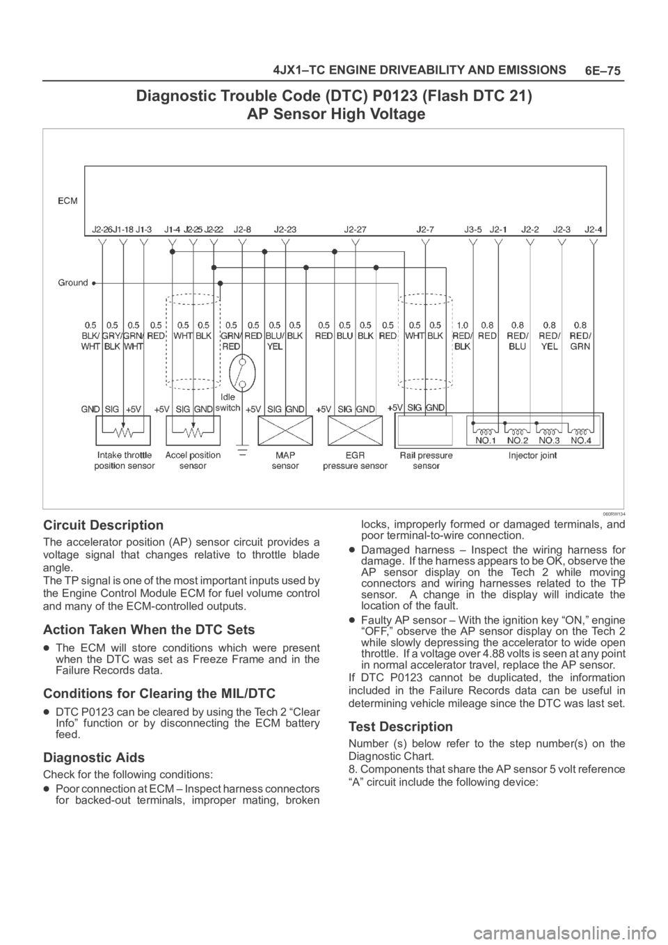
Diagnostic Trouble Code (DTC) P0123 (Flash DTC 21)
AP Sensor High Voltage
060RW134
Circuit Description
The accelerator position (AP) sensor circuit provides a
voltage signal that changes relative to throttle blade
angle.
The TP signal is one of the most important inputs used by
the Engine Control Module ECM for fuel volume control
and many of the ECM-controlled outputs.
Action Taken When the DTC Sets
The ECM will store conditions which were present
when the DTC was set as Freeze Frame and in the
Failure Records data.
Conditions for Clearing the MIL/DTC
DTC P0123 can be cleared by using the Tech 2 “Clear
Info” function or by disconnecting the ECM battery
feed.
Diagnostic Aids
Check for the following conditions:
Poor connection at ECM – Inspect harness connectors
for backed-out terminals, improper mating, brokenlocks, improperly formed or damaged terminals, and
poor terminal-to-wire connection.
Damaged harness – Inspect the wiring harness for
damage. If the harness appears to be OK, observe the
AP sensor display on the Tech 2 while moving
connectors and wiring harnesses related to the TP
sensor. A change in the display will indicate the
location of the fault.
Faulty AP sensor – With the ignition key “ON,” engine
“OFF,” observe the AP sensor display on the Tech 2
while slowly depressing the accelerator to wide open
throttle. If a voltage over 4.88 volts is seen at any point
in normal accelerator travel, replace the AP sensor.
If DTC P0123 cannot be duplicated, the information
included in the Failure Records data can be useful in
determining vehicle mileage since the DTC was last set.
Test Description
Number (s) below refer to the step number(s) on the
Diagnostic Chart.
8. Components that share the AP sensor 5 volt reference
“A” circuit include the following device:
Page 2039 of 6000
6E–146
4JX1–TC ENGINE DRIVEABILITY AND EMISSIONS
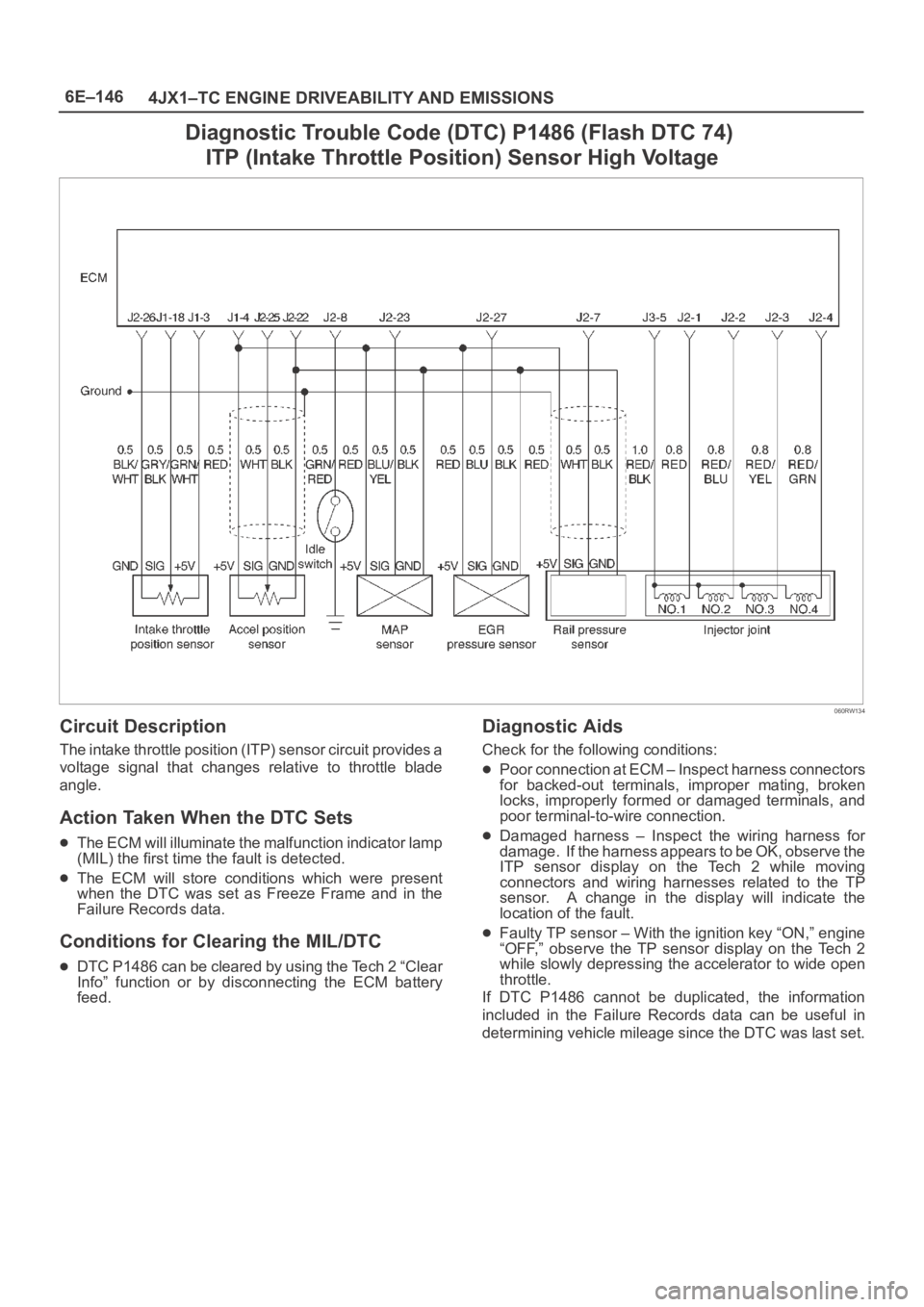
Diagnostic Trouble Code (DTC) P1486 (Flash DTC 74)
ITP (Intake Throttle Position) Sensor High Voltage
060RW134
Circuit Description
The intake throttle position (ITP) sensor circuit provides a
voltage signal that changes relative to throttle blade
angle.
Action Taken When the DTC Sets
The ECM will illuminate the malfunction indicator lamp
(MIL) the first time the fault is detected.
The ECM will store conditions which were present
when the DTC was set as Freeze Frame and in the
Failure Records data.
Conditions for Clearing the MIL/DTC
DTC P1486 can be cleared by using the Tech 2 “Clear
Info” function or by disconnecting the ECM battery
feed.
Diagnostic Aids
Check for the following conditions:
Poor connection at ECM – Inspect harness connectors
for backed-out terminals, improper mating, broken
locks, improperly formed or damaged terminals, and
poor terminal-to-wire connection.
Damaged harness – Inspect the wiring harness for
damage. If the harness appears to be OK, observe the
ITP sensor display on the Tech 2 while moving
connectors and wiring harnesses related to the TP
sensor. A change in the display will indicate the
location of the fault.
Faulty TP sensor – With the ignition key “ON,” engine
“OFF,” observe the TP sensor display on the Tech 2
while slowly depressing the accelerator to wide open
throttle.
If DTC P1486 cannot be duplicated, the information
included in the Failure Records data can be useful in
determining vehicle mileage since the DTC was last set.