1998 OPEL FRONTERA key
[x] Cancel search: keyPage 2081 of 6000
6E–188
4JX1–TC ENGINE DRIVEABILITY AND EMISSIONS
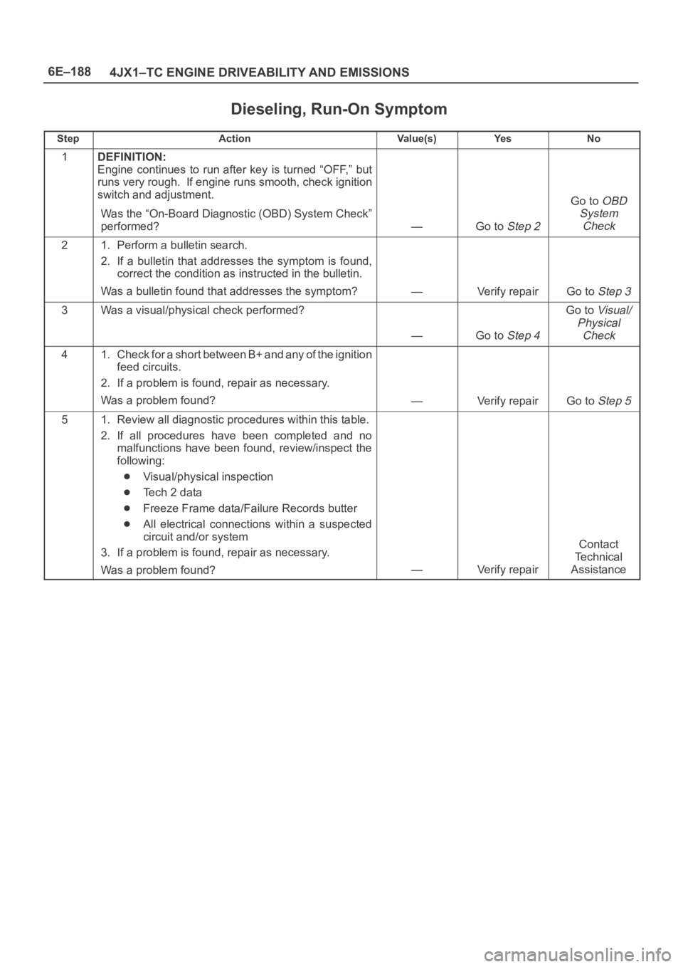
Dieseling, Run-On Symptom
StepActionVa l u e ( s )Ye sNo
1DEFINITION:
Engine continues to run after key is turned “OFF,” but
runs very rough. If engine runs smooth, check ignition
switch and adjustment.
Was the “On-Board Diagnostic (OBD) System Check”
performed?
—Go to Step 2
Go to OBD
System
Check
21. Perform a bulletin search.
2. If a bulletin that addresses the symptom is found,
correct the condition as instructed in the bulletin.
Was a bulletin found that addresses the symptom?
—Verify repairGo to Step 3
3Was a visual/physical check performed?
—Go to Step 4
Go to Visual/
Physical
Check
41. Check for a short between B+ and any of the ignition
feed circuits.
2. If a problem is found, repair as necessary.
Was a problem found?
—Verify repairGo to Step 5
51. Review all diagnostic procedures within this table.
2. If all procedures have been completed and no
malfunctions have been found, review/inspect the
following:
Visual/physical inspection
Te c h 2 d a t a
Freeze Frame data/Failure Records butter
All electrical connections within a suspected
circuit and/or system
3. If a problem is found, repair as necessary.
Was a problem found?
—Verify repair
Contact
Te c h n i c a l
Assistance
Page 2159 of 6000
7A–5 AUTOMATIC TRANSMISSION (4L30–E)
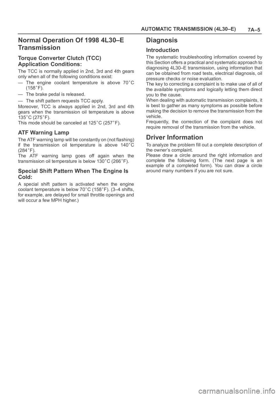
Normal Operation Of 1998 4L30–E
Tr a n s m i s s i o n
Torque Converter Clutch (TCC)
Application Conditions:
The TCC is normally applied in 2nd, 3rd and 4th gears
only when all of the following conditions exist:
— The engine coolant temperature is above 70
C
(158
F).
— The brake pedal is released.
— The shift pattern requests TCC apply.
Moreover, TCC is always applied in 2nd, 3rd and 4th
gears when the transmission oil temperature is above
135
C (275F).
This mode should be canceled at 125
C (257F).
ATF Warning Lamp
The ATF warning lamp will be constantly on (not flashing)
if the transmission oil temperature is above 140
C
(284
F).
The ATF warning lamp goes off again when the
transmission oil temperature is below 130
C (266F).
Special Shift Pattern When The Engine Is
Cold:
A special shift pattern is activated when the engine
coolant temperature is below 70
C (158F). (3–4 shifts,
for example, are delayed for small throttle openings and
will occur a few MPH higher.)
Diagnosis
Introduction
The systematic troubleshooting information covered by
this Section offers a practical and systematic approach to
diagnosing 4L30–E transmission, using information that
can be obtained from road tests, electrical diagnosis, oil
pressure checks or noise evaluation.
The key to correcting a complaint is to make use of all of
the available symptoms and logically letting them direct
you to the cause.
When dealing with automatic transmission complaints, it
is best to gather as many symptoms as possible before
making the decision to remove the transmission from the
vehicle.
Frequently, the correction of the complaint does not
require removal of the transmission from the vehicle.
Driver Information
To analyze the problem fill out a complete description of
the owner’s complaint.
Please draw a circle around the right information and
complete the following form. (The next page is an
example of a completed form). You can draw a circle
around many numbers if you are not sure.
Page 2173 of 6000
7A–19 AUTOMATIC TRANSMISSION (4L30–E)
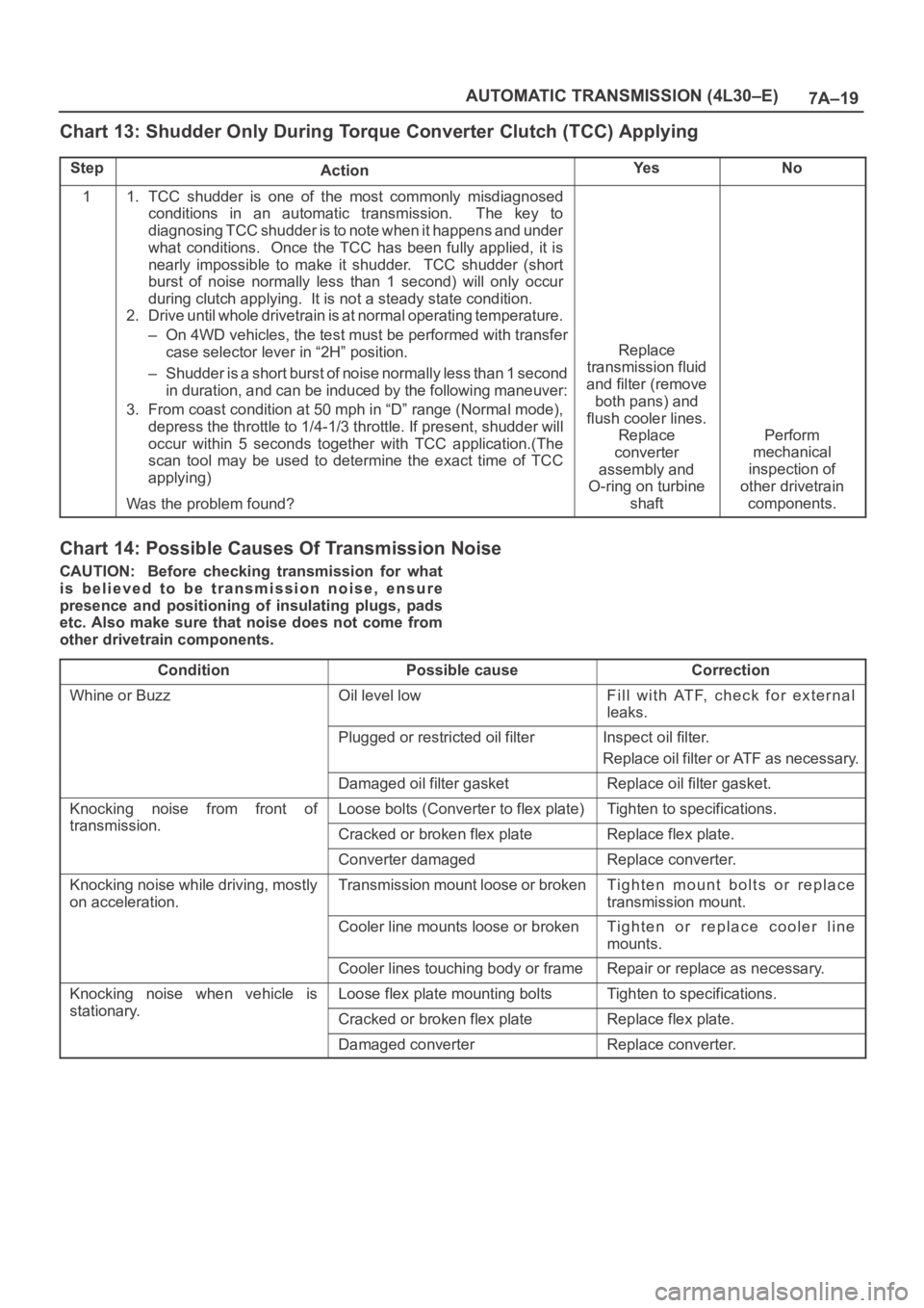
Chart 13: Shudder Only During Torque Converter Clutch (TCC) Applying
StepActionYe sNo
11. TCC shudder is one of the most commonly misdiagnosed
conditions in an automatic transmission. The key to
diagnosing TCC shudder is to note when it happens and under
what conditions. Once the TCC has been fully applied, it is
nearly impossible to make it shudder. TCC shudder (short
burst of noise normally less than 1 second) will only occur
during clutch applying. It is not a steady state condition.
2. Drive until whole drivetrain is at normal operating temperature.
– On 4WD vehicles, the test must be performed with transfer
case selector lever in “2H” position.
– Shudder is a short burst of noise normally less than 1 second
in duration, and can be induced by the following maneuver:
3. From coast condition at 50 mph in “D” range (Normal mode),
depress the throttle to 1/4-1/3 throttle. If present, shudder will
occur within 5 seconds together with TCC application.(The
scan tool may be used to determine the exact time of TCC
applying)
Was the problem found?
Replace
transmission fluid
and filter (remove
both pans) and
flush cooler lines.
Replace
converter
assembly and
O-ring on turbine
shaft
Perform
mechanical
inspection of
other drivetrain
components.
Chart 14: Possible Causes Of Transmission Noise
CAUTION: Before checking transmission for what
is believed to be transmission noise, ensure
presence and positioning of insulating plugs, pads
etc. Also make sure that noise does not come from
other drivetrain components.
Condition
Possible causeCorrection
Whine or BuzzOil level lowFill with ATF, check for external
leaks.
Plugged or restricted oil filterInspect oil filter.
Replace oil filter or ATF as necessary.
Damaged oil filter gasketReplace oil filter gasket.
Knocking noise from front of
transmission
Loose bolts (Converter to flex plate)Tighten to specifications.
transmission.Cracked or broken flex plateReplace flex plate.
Converter damagedReplace converter.
Knocking noise while driving, mostly
on acceleration.Transmission mount loose or brokenTighten mount bolts or replace
transmission mount.
Cooler line mounts loose or brokenTighten or replace cooler line
mounts.
Cooler lines touching body or frameRepair or replace as necessary.
Knocking noise when vehicle is
stationary
Loose flex plate mounting boltsTighten to specifications.
stationary.Cracked or broken flex plateReplace flex plate.
Damaged converterReplace converter.
Page 2182 of 6000
7A–28
AUTOMATIC TRANSMISSION (4L30–E)
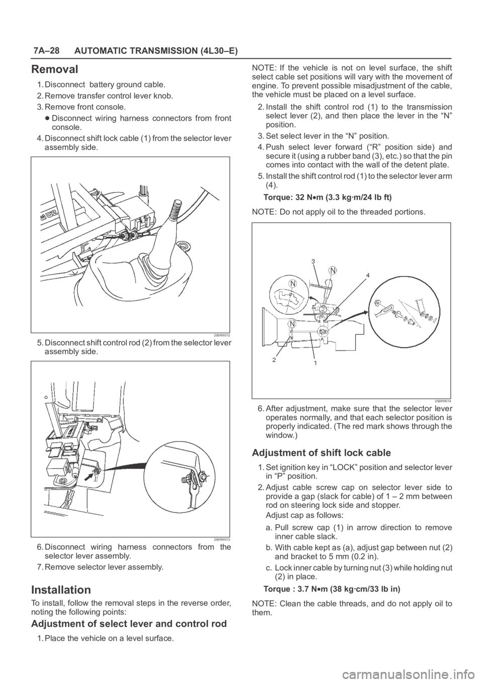
Removal
1. Disconnect battery ground cable.
2. Remove transfer control lever knob.
3. Remove front console.
Disconnect wiring harness connectors from front
console.
4. Disconnect shift lock cable (1) from the selector lever
assembly side.
256RW012
5. Disconnect shift control rod (2) from the selector lever
assembly side.
256RW013
6. Disconnect wiring harness connectors from the
selector lever assembly.
7. Remove selector lever assembly.
Installation
To install, follow the removal steps in the reverse order,
noting the following points:
Adjustment of select lever and control rod
1. Place the vehicle on a level surface.NOTE: If the vehicle is not on level surface, the shift
select cable set positions will vary with the movement of
engine. To prevent possible misadjustment of the cable,
the vehicle must be placed on a level surface.
2. Install the shift control rod (1) to the transmission
select lever (2), and then place the lever in the “N”
position.
3. Set select lever in the “N” position.
4. Push select lever forward (“R” position side) and
s e c u r e i t ( u s i n g a r u b b e r b a n d ( 3 ) , e t c . ) s o t h a t t h e p i n
comes into contact with the wall of the detent plate.
5. Install the shift control rod (1) to the selector lever arm
(4).
To r q u e : 3 2 N
m (3.3 kgꞏm/24 lb ft)
NOTE: Do not apply oil to the threaded portions.
256RW014
6. After adjustment, make sure that the selector lever
operates normally, and that each selector position is
properly indicated. (The red mark shows through the
window.)
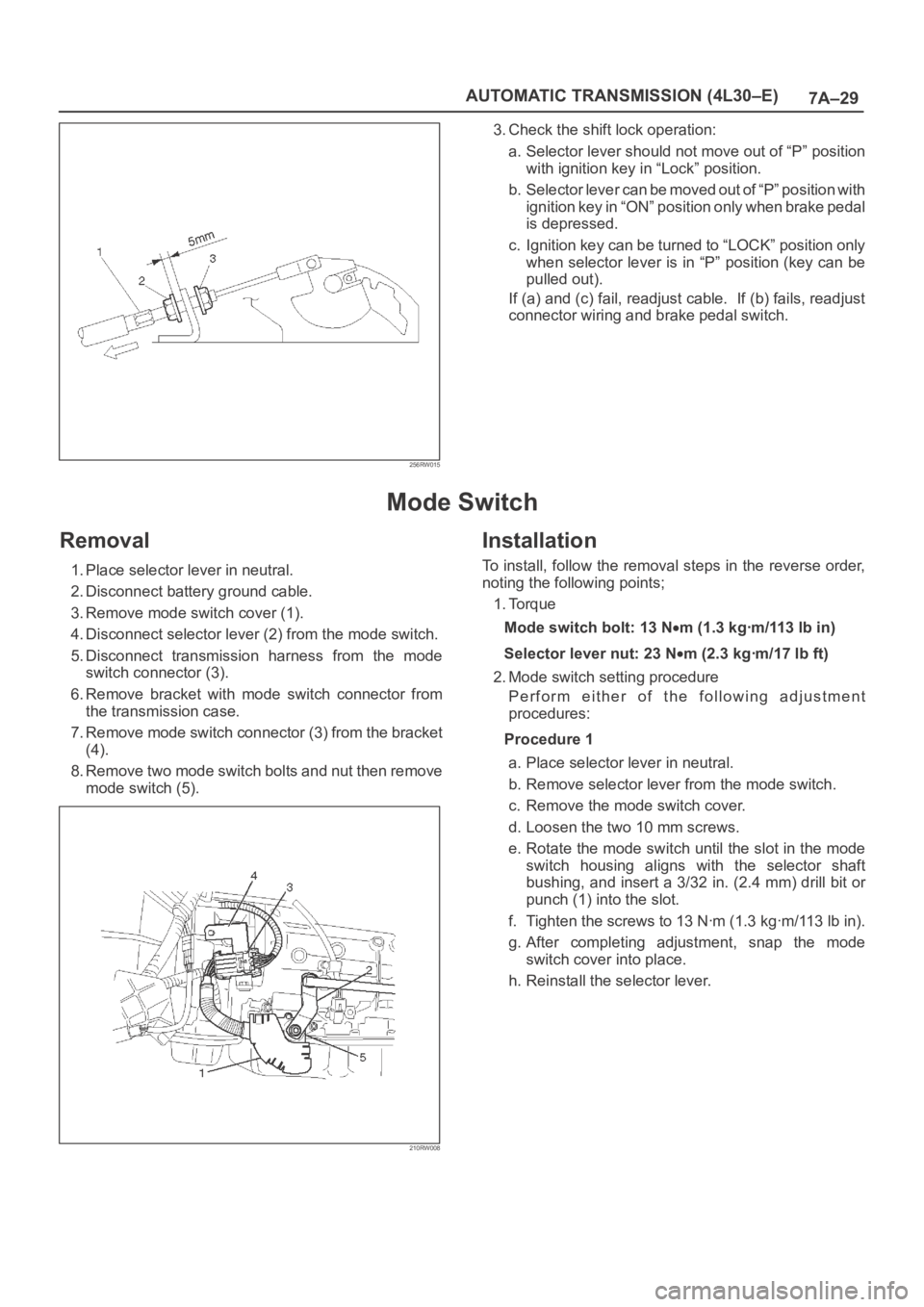
Adjustment of shift lock cable
1. Set ignition key in “LOCK” position and selector lever
in “P” position.
2. Adjust cable screw cap on selector lever side to
provide a gap (slack for cable) of 1 – 2 mm between
rod on steering lock side and stopper.
Adjust cap as follows:
a. Pull screw cap (1) in arrow direction to remove
inner cable slack.
b. With cable kept as (a), adjust gap between nut (2)
and bracket to 5 mm (0.2 in).
c. Lock inner cable by turning nut (3) while holding nut
(2) in place.
Torque : 3.7 N
m (38 kgꞏcm/33 lb in)
NOTE: Clean the cable threads, and do not apply oil to
them.
Page 2183 of 6000
7A–29 AUTOMATIC TRANSMISSION (4L30–E)
256RW015
3. Check the shift lock operation:
a. Selector lever should not move out of “P” position
with ignition key in “Lock” position.
b. Selector lever can be moved out of “P” position with
ignition key in “ON” position only when brake pedal
is depressed.
c. Ignition key can be turned to “LOCK” position only
when selector lever is in “P” position (key can be
pulled out).
If (a) and (c) fail, readjust cable. If (b) fails, readjust
connector wiring and brake pedal switch.
Mode Switch
Removal
1. Place selector lever in neutral.
2. Disconnect battery ground cable.
3. Remove mode switch cover (1).
4. Disconnect selector lever (2) from the mode switch.
5. Disconnect transmission harness from the mode
switch connector (3).
6. Remove bracket with mode switch connector from
the transmission case.
7. Remove mode switch connector (3) from the bracket
(4).
8. Remove two mode switch bolts and nut then remove
mode switch (5).
210RW008
Installation
To install, follow the removal steps in the reverse order,
noting the following points;
1. Torque
Mode switch bolt: 13 N
m(1.3kgꞏm/113lbin)
Selector lever nut: 23 N
m (2.3 kgꞏm/17 lb ft)
2. Mode switch setting procedure
Perform either of the following adjustment
procedures:
Procedure 1
a. Place selector lever in neutral.
b. Remove selector lever from the mode switch.
c. Remove the mode switch cover.
d. Loosen the two 10 mm screws.
e. Rotate the mode switch until the slot in the mode
switch housing aligns with the selector shaft
bushing, and insert a 3/32 in. (2.4 mm) drill bit or
punch (1) into the slot.
f. Tighten the screws to 13 Nꞏm (1.3 kgꞏm/113 lb in).
g. After completing adjustment, snap the mode
switch cover into place.
h. Reinstall the selector lever.
Page 2254 of 6000
TRANSMISSION CONTROL SYSTEM (4L30–E)7A1–9
Winter Drive Mode
1.Operation
The winter switch will operate when switched on after
all of the following conditions are present:
a. The gear select position is “D”, “N”, “R” and “P”
range.
b. Vehicle speed is 7 mph (11 km/h) or less.
c. Transmission oil temperature is 120
C (248F) or
less.
d. Kickdown switch is off.
e. Accelerator opening is at 8% or less.
2.Cancel Release
1. Cancellation by driver
a. Turning off the winter drive mode switch
b. Shifting select position to “3”, “2”, or “L” (Winter
drive mode is not canceled by selecting “D”, “N”,
“R”, or “P”)
c. Ignition key is turned off.
2. Automatic cancellation
a. When vehicle runs at 21mph (34 km/h) or more
for 1 second or more
b. When transmission oil temperature reaches
140
C (284F) or above
NOTE: The mode returns to normal drive mode or power
drive mode after the winter drive mode is canceled.
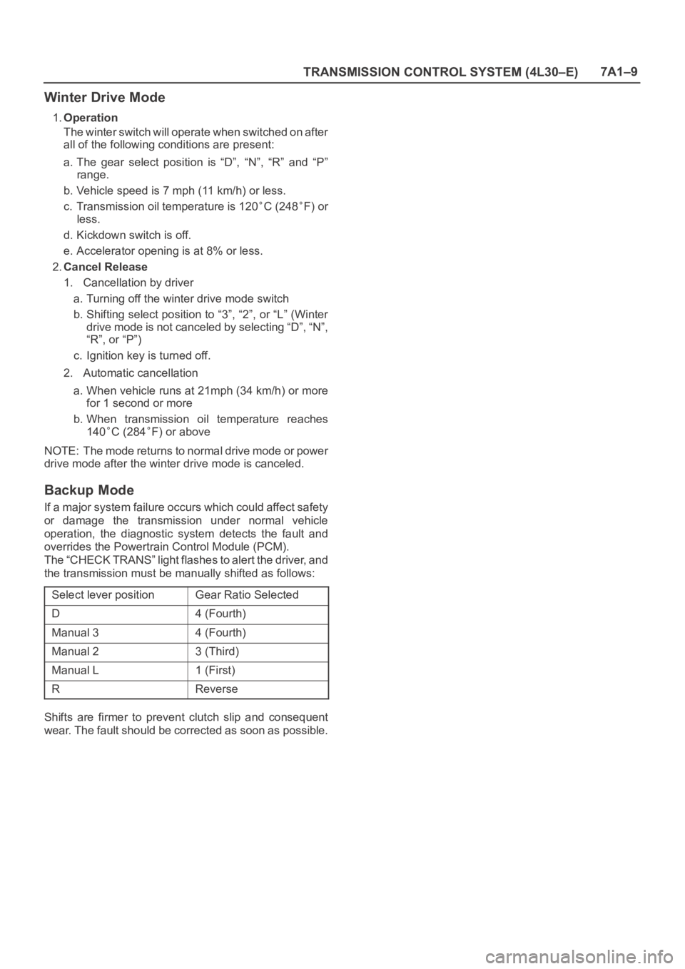
Backup Mode
If a major system failure occurs which could affect safety
or damage the transmission under normal vehicle
operation, the diagnostic system detects the fault and
overrides the Powertrain Control Module (PCM).
The “CHECK TRANS” light flashes to alert the driver, and
the transmission must be manually shifted as follows:
Select lever position
Gear Ratio Selected
D4 (Fourth)
Manual 34 (Fourth)
Manual 23 (Third)
Manual L1 (First)
RReverse
Shifts are firmer to prevent clutch slip and consequent
wear. The fault should be corrected as soon as possible.
Page 2256 of 6000
TRANSMISSION CONTROL SYSTEM (4L30–E)7A1–11
Diagnosis
Electronic Diagnosis
How To Diagnose The Problem
1. To avoid incorrect diagnostics, this book needs to be
followed accurately. Unless stated, do not jump
directly to a section that could contain the solution.
Some important information may be missed.
2. The sections in CAPITALS and bold are the main
sections that can be found in the contents.
3. The GOTO “SECTION” means to continue to check
going to the “section”.
4. The GOTHROUGH “SECTION” means to go
through the “section” and then to go back to the place
the GOTHROUGH was written.
5. BASIC ELECTRIC CIRCUITS:
You should understand the basic theory of electricity.
This includes the meaning of voltage, amps, ohms,
and what happens in a circuit with an open or shorted
wire. You should also be able to read and understand
wiring diagrams.
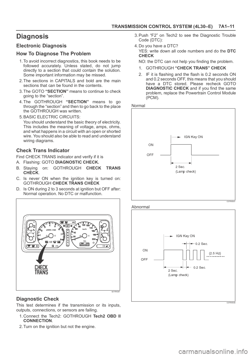
Check Trans Indicator
Find CHECK TRANS indicator and verify if it is
A. Flashing: GOTO DIAGNOSTIC CHECK.
B. Staying on: GOTHROUGH CHECK TRANS
CHECK.
C. Is never ON when the ignition key is turned on:
GOTHROUGH CHECK TRANS CHECK
D. Is ON during 2 to 3 seconds at ignition but OFF after:
Normal operation. No DTC or malfunction.
821RW261
Diagnostic Check
This test determines if the transmission or its inputs,
outputs, connections, or sensors are failing.
1. Connect the Tech2: GOTHROUGH Te c h 2 O B D I I
CONNECTION.
2. Turn on the ignition but not the engine.3. Push “F2” on Tech2 to see the Diagnostic Trouble
Code (DTC):
4. Do you have a DTC?
YES: write down all code numbers and do the DTC
CHECK
NO: the DTC can not help you finding the problem.
1. GOTHROUGH “CHECK TRANS” CHECK
2. IF it is flashing and the flash is 0.2 seconds ON
and 0.2 seconds OFF, this means that you should
have a DTC stored. Please recheck GOTO
DIAGNOSTIC CHECK and if you find the same
problem, replace the Powertrain Control Module
(PCM).
Normal
C07RW047
Abnormal
C07RW048
Page 2541 of 6000
8A–2LIGHTING SYSTEM
Vanity Mirror Illumination Bulb 8A–16. . . . . . . . . . . . .
Removal 8A–16. . . . . . . . . . . . . . . . . . . . . . . . . . . . .
Installation 8A–16. . . . . . . . . . . . . . . . . . . . . . . . . . .
Starter Switch 8A–17. . . . . . . . . . . . . . . . . . . . . . . . . . .
Removal 8A–17. . . . . . . . . . . . . . . . . . . . . . . . . . . . .
Installation 8A–17. . . . . . . . . . . . . . . . . . . . . . . . . . . .
Lighting Switch (Combination Switch) 8A–18. . . . . .
Removal 8A–18. . . . . . . . . . . . . . . . . . . . . . . . . . . . .
Installation 8A–18. . . . . . . . . . . . . . . . . . . . . . . . . . . .
Fog Light Switch 8A–19. . . . . . . . . . . . . . . . . . . . . . . .
Removal 8A–19. . . . . . . . . . . . . . . . . . . . . . . . . . . . .
Installation 8A–19. . . . . . . . . . . . . . . . . . . . . . . . . . . .
Stoplight Switch (W/O Cruise Control) 8A–20. . . . . .
Removal 8A–20. . . . . . . . . . . . . . . . . . . . . . . . . . . . .
Installation 8A–20. . . . . . . . . . . . . . . . . . . . . . . . . . . .
Brake Switch (W/Cruise Control) 8A–21. . . . . . . . . .
Removal 8A–21. . . . . . . . . . . . . . . . . . . . . . . . . . . . .
Installation 8A–21. . . . . . . . . . . . . . . . . . . . . . . . . . . .
Turn Signal Switch (Combination Switch) 8A–21. . .
Removal and Installation 8A–21. . . . . . . . . . . . . . .
Hazard Warning Switch 8A–22. . . . . . . . . . . . . . . . . .
Removal 8A–22. . . . . . . . . . . . . . . . . . . . . . . . . . . . . Installation 8A–22. . . . . . . . . . . . . . . . . . . . . . . . . . . .
Tailgate Switch 8A–23. . . . . . . . . . . . . . . . . . . . . . . . . .
Removal 8A–23. . . . . . . . . . . . . . . . . . . . . . . . . . . . .
Installation 8A–23. . . . . . . . . . . . . . . . . . . . . . . . . . . .
Door Switch 8A–23. . . . . . . . . . . . . . . . . . . . . . . . . . . .
Removal 8A–23. . . . . . . . . . . . . . . . . . . . . . . . . . . . .
Installation 8A–23. . . . . . . . . . . . . . . . . . . . . . . . . . . .
Rear Defogger Switch 8A–24. . . . . . . . . . . . . . . . . . .
Removal 8A–24. . . . . . . . . . . . . . . . . . . . . . . . . . . . .
Installation 8A–24. . . . . . . . . . . . . . . . . . . . . . . . . . .
Seat Heater Switch 8A–25. . . . . . . . . . . . . . . . . . . . . .
Removal 8A–25. . . . . . . . . . . . . . . . . . . . . . . . . . . . .
Installation 8A–25. . . . . . . . . . . . . . . . . . . . . . . . . . . .
Key Remind Switch (Starter Switch) 8A–25. . . . . . .
Removal and Installation 8A–25. . . . . . . . . . . . . . .
Illumination Controller 8A–26. . . . . . . . . . . . . . . . . . . .
Removal 8A–26. . . . . . . . . . . . . . . . . . . . . . . . . . . . .
Installation 8A–26. . . . . . . . . . . . . . . . . . . . . . . . . . .
Power/Winter Switch 8A–27. . . . . . . . . . . . . . . . . . . . .
Removal 8A–27. . . . . . . . . . . . . . . . . . . . . . . . . . . . .
Installation 8A–27. . . . . . . . . . . . . . . . . . . . . . . . . . .
Main Data and Specifications 8A–28. . . . . . . . . . . . .
Service Precaution
WARNING: IF SO EQUIPPED WITH A
SUPPLEMENTAL RESTRAINT SYSTEM (SRS),
REFER TO THE SRS COMPONENT AND WIRING
LOCATION VIEW IN ORDER TO DETERMINE
WHETHER YOU ARE PERFORMING SERVICE ON OR
NEAR THE SRS COMPONENTS OR THE SRS
WIRING. WHEN YOU ARE PERFORMING SERVICE
ON OR NEAR THE SRS COMPONENTS OR THE SRS
WIRING, REFER TO THE SRS SERVICE
INFORMATION. FAILURE TO FOLLOW WARNINGS
COULD RESULT IN POSSIBLE AIR BAG
DEPLOYMENT, PERSONAL INJURY, OR
OTHERWISE UNNEEDED SRS SYSTEM REPAIRS.
CAUTION: Always use the correct fastener in the
proper location. When you replace a fastener, use
ONLY the exact part number for that application.
ISUZU will call out those fasteners that require a
replacement after removal. ISUZU will also call out
the fasteners that require thread lockers or thread
sealant. UNLESS OTHERWISE SPECIFIED, do not
use supplemental coatings (Paints, greases, or other
corrosion inhibitors) on threaded fasteners or
fastener joint interfaces. Generally, such coatings
adversely affect the fastener torque and the joint
clamping force, and may damage the fastener. When
you install fasteners, use the correct tightening
sequence and specifications. Following these
instructions can help you avoid damage to parts and
systems.