1998 OPEL FRONTERA brake fluid
[x] Cancel search: brake fluidPage 2246 of 6000
TRANSMISSION CONTROL SYSTEM (4L30–E)7A1–1
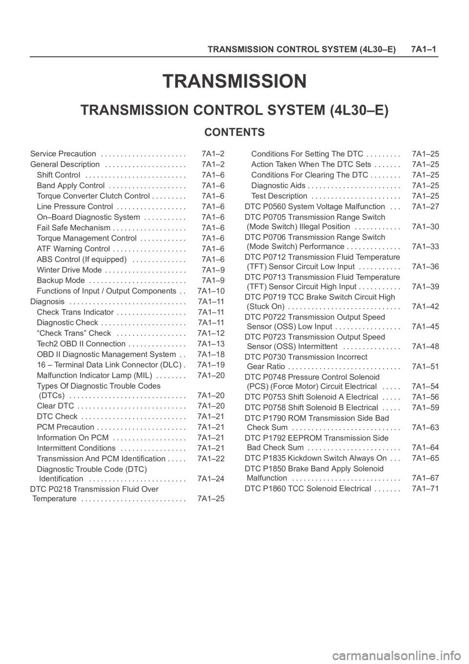
TRANSMISSION
TRANSMISSION CONTROL SYSTEM (4L30–E)
CONTENTS
Service Precaution 7A1–2. . . . . . . . . . . . . . . . . . . . . .
General Description 7A1–2. . . . . . . . . . . . . . . . . . . . .
Shift Control 7A1–6. . . . . . . . . . . . . . . . . . . . . . . . . .
Band Apply Control 7A1–6. . . . . . . . . . . . . . . . . . . .
Torque Converter Clutch Control 7A1–6. . . . . . . . .
Line Pressure Control 7A1–6. . . . . . . . . . . . . . . . . .
On–Board Diagnostic System 7A1–6. . . . . . . . . . .
Fail Safe Mechanism 7A1–6. . . . . . . . . . . . . . . . . . .
Torque Management Control 7A1–6. . . . . . . . . . . .
ATF Warning Control 7A1–6. . . . . . . . . . . . . . . . . . .
ABS Control (If equipped) 7A1–6. . . . . . . . . . . . . .
Winter Drive Mode 7A1–9. . . . . . . . . . . . . . . . . . . . .
Backup Mode 7A1–9. . . . . . . . . . . . . . . . . . . . . . . . .
Functions of Input / Output Components 7A1–10. .
Diagnosis 7A1–11. . . . . . . . . . . . . . . . . . . . . . . . . . . . . .
Check Trans Indicator 7A1–11. . . . . . . . . . . . . . . . . .
Diagnostic Check 7A1–11. . . . . . . . . . . . . . . . . . . . . .
“Check Trans” Check 7A1–12. . . . . . . . . . . . . . . . . .
Tech2 OBD II Connection 7A1–13. . . . . . . . . . . . . . .
OBD II Diagnostic Management System 7A1–18. .
16 – Terminal Data Link Connector (DLC) 7A1–19.
Malfunction Indicator Lamp (MIL) 7A1–20. . . . . . . .
Types Of Diagnostic Trouble Codes
(DTCs) 7A1–20. . . . . . . . . . . . . . . . . . . . . . . . . . . . . .
Clear DTC 7A1–20. . . . . . . . . . . . . . . . . . . . . . . . . . . .
DTC Check 7A1–21. . . . . . . . . . . . . . . . . . . . . . . . . . .
PCM Precaution 7A1–21. . . . . . . . . . . . . . . . . . . . . . .
Information On PCM 7A1–21. . . . . . . . . . . . . . . . . . .
Intermittent Conditions 7A1–21. . . . . . . . . . . . . . . . .
Transmission And PCM Identification 7A1–22. . . . .
Diagnostic Trouble Code (DTC)
Identification 7A1–24. . . . . . . . . . . . . . . . . . . . . . . . .
DTC P0218 Transmission Fluid Over
Temperature 7A1–25. . . . . . . . . . . . . . . . . . . . . . . . . . . Conditions For Setting The DTC 7A1–25. . . . . . . . .
Action Taken When The DTC Sets 7A1–25. . . . . . .
Conditions For Clearing The DTC 7A1–25. . . . . . . .
Diagnostic Aids 7A1–25. . . . . . . . . . . . . . . . . . . . . . . .
Test Description 7A1–25. . . . . . . . . . . . . . . . . . . . . . .
DTC P0560 System Voltage Malfunction 7A1–27. . .
DTC P0705 Transmission Range Switch
(Mode Switch) Illegal Position 7A1–30. . . . . . . . . . . .
DTC P0706 Transmission Range Switch
(Mode Switch) Performance 7A1–33. . . . . . . . . . . . . .
DTC P0712 Transmission Fluid Temperature
(TFT) Sensor Circuit Low Input 7A1–36. . . . . . . . . . .
DTC P0713 Transmission Fluid Temperature
(TFT) Sensor Circuit High Input 7A1–39. . . . . . . . . . .
DTC P0719 TCC Brake Switch Circuit High
(Stuck On) 7A1–42. . . . . . . . . . . . . . . . . . . . . . . . . . . . .
DTC P0722 Transmission Output Speed
Sensor (OSS) Low Input 7A1–45. . . . . . . . . . . . . . . . .
DTC P0723 Transmission Output Speed
Sensor (OSS) Intermittent 7A1–48. . . . . . . . . . . . . . .
DTC P0730 Transmission Incorrect
Gear Ratio 7A1–51. . . . . . . . . . . . . . . . . . . . . . . . . . . . .
DTC P0748 Pressure Control Solenoid
(PCS) (Force Motor) Circuit Electrical 7A1–54. . . . .
DTC P0753 Shift Solenoid A Electrical 7A1–56. . . . .
DTC P0758 Shift Solenoid B Electrical 7A1–59. . . . .
DTC P1790 ROM Transmission Side Bad
Check Sum 7A1–63. . . . . . . . . . . . . . . . . . . . . . . . . . . .
DTC P1792 EEPROM Transmission Side
Bad Check Sum 7A1–64. . . . . . . . . . . . . . . . . . . . . . . .
DTC P1835 Kickdown Switch Always On 7A1–65. . .
DTC P1850 Brake Band Apply Solenoid
Malfunction 7A1–67. . . . . . . . . . . . . . . . . . . . . . . . . . . .
DTC P1860 TCC Solenoid Electrical 7A1–71. . . . . . .
Page 2269 of 6000
7A1–24
TRANSMISSION CONTROL SYSTEM (4L30–E)
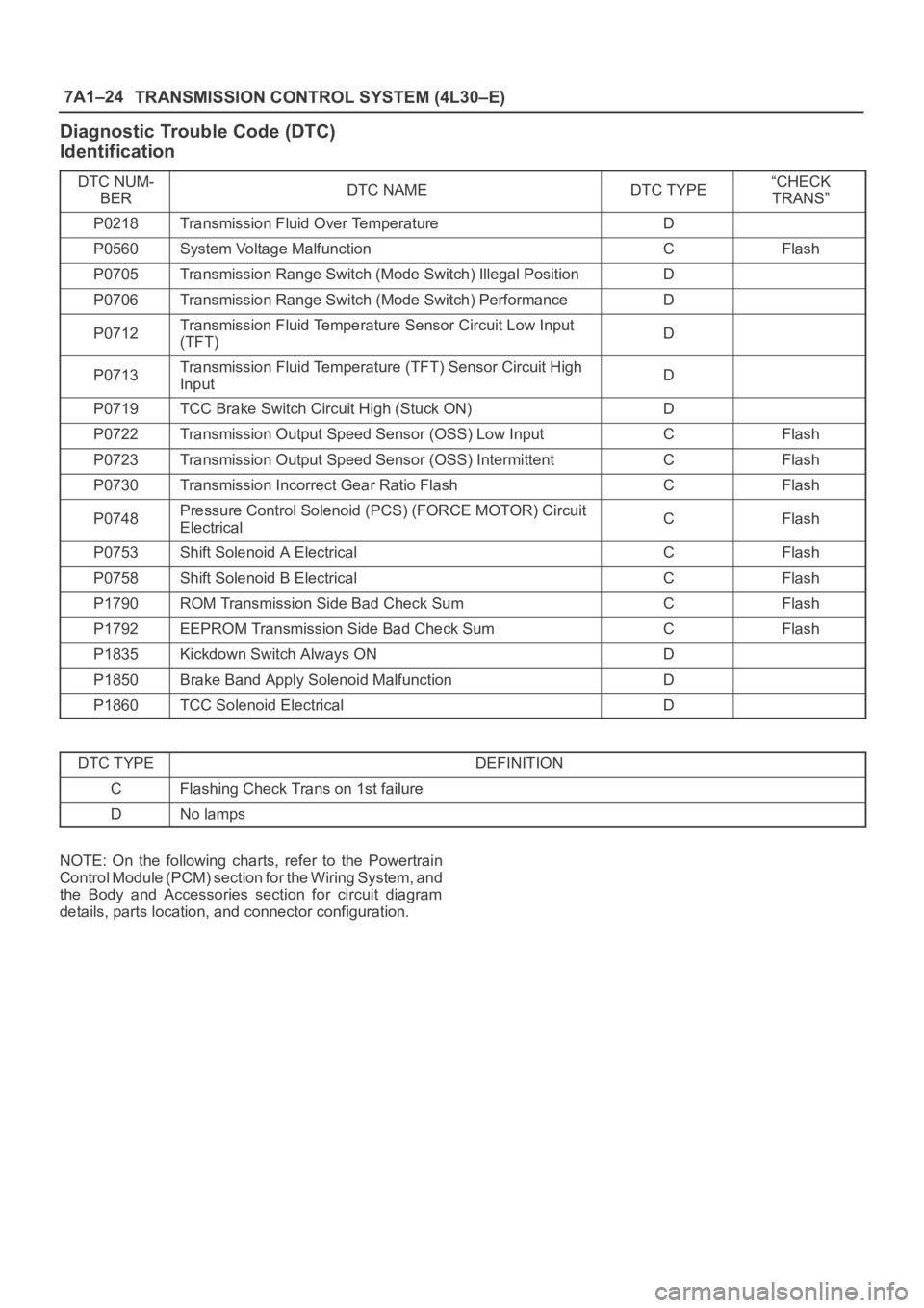
Diagnostic Trouble Code (DTC)
Identification
DTC NUM-
BERDTC NAMEDTC TYPE“CHECK
TRANS”
P0218Transmission Fluid Over TemperatureD
P0560System Voltage MalfunctionCFlash
P0705Transmission Range Switch (Mode Switch) Illegal PositionD
P0706Transmission Range Switch (Mode Switch) PerformanceD
P0712Transmission Fluid Temperature Sensor Circuit Low Input
(TFT)D
P0713Transmission Fluid Temperature (TFT) Sensor Circuit High
InputD
P0719TCC Brake Switch Circuit High (Stuck ON)D
P0722Transmission Output Speed Sensor (OSS) Low InputCFlash
P0723Transmission Output Speed Sensor (OSS) IntermittentCFlash
P0730Transmission Incorrect Gear Ratio FlashCFlash
P0748Pressure Control Solenoid (PCS) (FORCE MOTOR) Circuit
ElectricalCFlash
P0753Shift Solenoid A ElectricalCFlash
P0758Shift Solenoid B ElectricalCFlash
P1790ROM Transmission Side Bad Check SumCFlash
P1792EEPROM Transmission Side Bad Check SumCFlash
P1835Kickdown Switch Always OND
P1850Brake Band Apply Solenoid MalfunctionD
P1860TCC Solenoid ElectricalD
DTC TYPEDEFINITION
CFlashing Check Trans on 1st failure
DNo lamps
NOTE: On the following charts, refer to the Powertrain
Control Module (PCM) section for the Wiring System, and
the Body and Accessories section for circuit diagram
details, parts location, and connector configuration.
Page 2312 of 6000
TRANSMISSION CONTROL SYSTEM (4L30–E)7A1–67
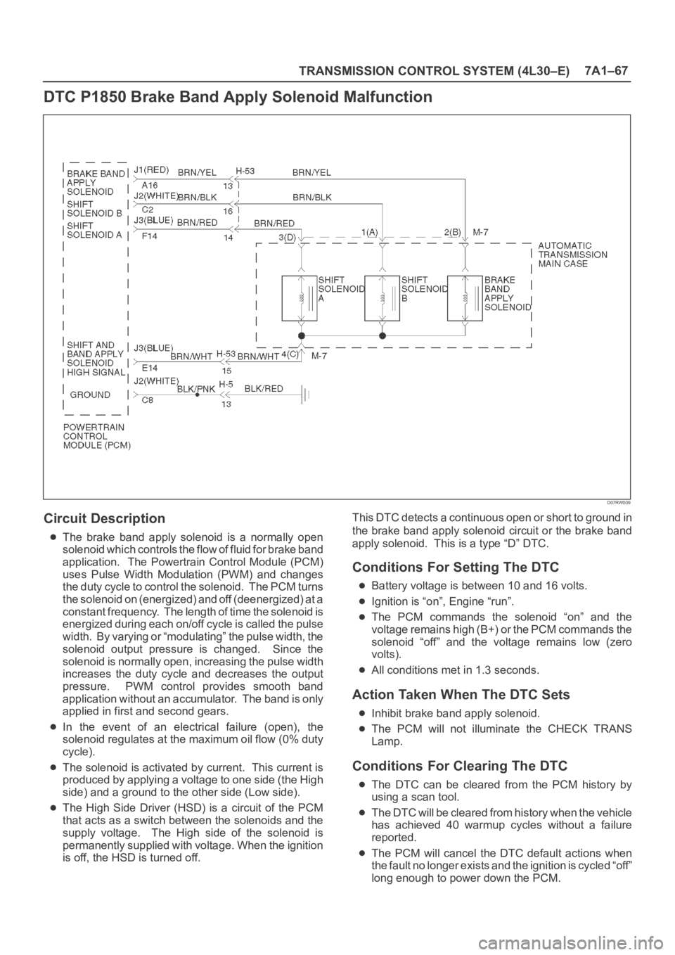
DTC P1850 Brake Band Apply Solenoid Malfunction
D07RW009
Circuit Description
The brake band apply solenoid is a normally open
solenoid which controls the flow of fluid for brake band
application. The Powertrain Control Module (PCM)
uses Pulse Width Modulation (PWM) and changes
the duty cycle to control the solenoid. The PCM turns
the solenoid on (energized) and off (deenergized) at a
constant frequency. The length of time the solenoid is
energized during each on/off cycle is called the pulse
width. By varying or “modulating” the pulse width, the
solenoid output pressure is changed. Since the
solenoid is normally open, increasing the pulse width
increases the duty cycle and decreases the output
pressure. PWM control provides smooth band
application without an accumulator. The band is only
applied in first and second gears.
In the event of an electrical failure (open), the
solenoid regulates at the maximum oil flow (0% duty
cycle).
The solenoid is activated by current. This current is
produced by applying a voltage to one side (the High
side) and a ground to the other side (Low side).
The High Side Driver (HSD) is a circuit of the PCM
that acts as a switch between the solenoids and the
supply voltage. The High side of the solenoid is
permanently supplied with voltage. When the ignition
is off, the HSD is turned off.This DTC detects a continuous open or short to ground in
the brake band apply solenoid circuit or the brake band
apply solenoid. This is a type “D” DTC.
Conditions For Setting The DTC
Battery voltage is between 10 and 16 volts.
Ignition is “on”, Engine “run”.
The PCM commands the solenoid “on” and the
voltage remains high (B+) or the PCM commands the
solenoid “off” and the voltage remains low (zero
volts).
All conditions met in 1.3 seconds.
Action Taken When The DTC Sets
Inhibit brake band apply solenoid.
The PCM will not illuminate the CHECK TRANS
Lamp.
Conditions For Clearing The DTC
The DTC can be cleared from the PCM history by
using a scan tool.
The DTC will be cleared from history when the vehicle
has achieved 40 warmup cycles without a failure
reported.
The PCM will cancel the DTC default actions when
the fault no longer exists and the ignition is cycled “off”
long enough to power down the PCM.
Page 2529 of 6000
7C–20CLUTCH
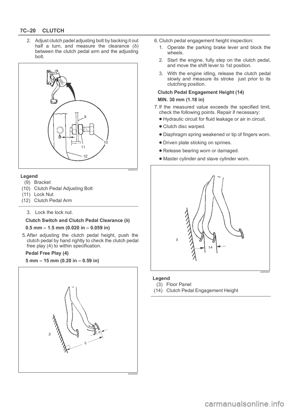
2. Adjust clutch padel adjusting bolt by backing it out
half a turn, and measure the clearance (
)
between the clutch pedal arm and the adjusting
bolt.
203RW010
Legend
(9) Bracket
(10) Clutch Pedal Adjusting Bolt
(11) Lock Nut
(12) Clutch Pedal Arm
3. Lock the lock nut.
Clutch Switch and Clutch Pedal Clearance (
)
0.5 mm – 1.5 mm (0.020 in – 0.059 in)
5. After adjusting the clutch pedal height, push the
clutch pedal by hand rightly to check the clutch pedal
free play (4) to within specification.
Pedal Free Play (4)
5 mm – 15 mm (0.20 in – 0.59 in)
203RW004
6. Clutch pedal engagement height inspection:
1. Operate the parking brake lever and block the
wheels.
2. Start the engine, fully step on the clutch pedal,
and move the shift lever to 1st position.
3. With the engine idling, release the clutch pedal
slowly and measure its stroke just prior to its
clutching position.
Clutch Pedal Engagement Height (14)
MIN. 30 mm (1.18 in)
7. If the measured value exceeds the specified limit,
check the following points. Repair if necessary:
Hydraulic circuit for fluid leakage or air in circuit.
Clutch disc warped.
Diaphragm spring weakened or tip of fingers worn.
Driven plate sticking on sprines.
Release bearing worn or damaged.
Master cylinder and slave cylinder worn.
203RW007
Legend
(3) Floor Panel
(14) Clutch Pedal Engagement Height
Page 3006 of 6000
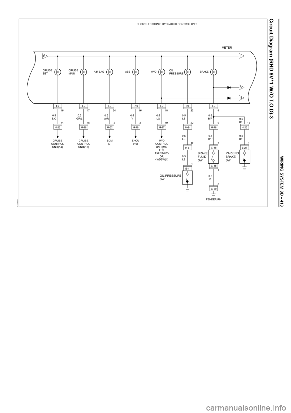
D08RW725
G
H
FE
16
14 CRUISE
SETCRUISE
MAINAIR BAG ABS 4WD BRAKEEHCU:ELECTRONIC HYDRAULIC CONTROL UNIT
OIL
PRESSURE
CRUISE
CONTROL
UNIT(14)0.5
B/OI-9
H-2617
15
CRUISE
CONTROL
UNIT(13) 0.5
GR/LI-9
H-2624
2
SDM
(7) 0.5
W/RI-9
H-6216
2
EHCU
(16)
OIL PRESSURE
SWBRAKE
FLUID
SWPARKING
BRAKE
SW
0.5
YI-10
H-1618
19
4WD
CONTROL
UNIT(19)/
FRT
AXLESW(2)
OR
4WDSW(1)0.5
LGI-9
H-2722
22
12
1 0.5
LB
0.5
LB0.5
B/P
0.5
B0.5
B/P0.5
B/P
0.5
LBI-9
H-9
H-6
E-14
1
8 9
213
1
FENDER-RH0.5
B/PI-9
H-16
C-15
C-39 C-15H-26
B-27
METER
Page 3012 of 6000
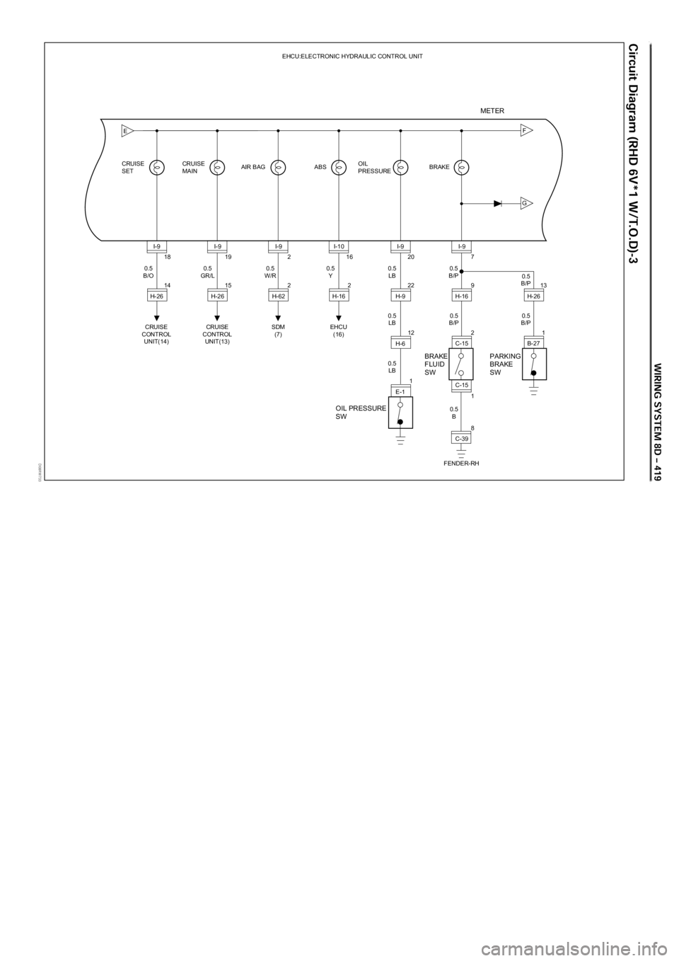
D08RW733
G
FE
18
14 CRUISE
SETCRUISE
MAINAIR BAG ABS BRAKEEHCU:ELECTRONIC HYDRAULIC CONTROL UNIT
OIL
PRESSURE
CRUISE
CONTROL
UNIT(14)0.5
B/OI-9
H-2619
15
CRUISE
CONTROL
UNIT(13) 0.5
GR/LI-9
H-262
2
SDM
(7) 0.5
W/RI-9
H-6216
2
EHCU
(16)
OIL PRESSURE
SWBRAKE
FLUID
SWPARKING
BRAKE
SW
0.5
YI-10
H-1620
22
12
1 0.5
LB
0.5
LB0.5
B/P
0.5
B0.5
B/P0.5
B/P
0.5
LBI-9
H-9
H-6
E-17
1
8 9
213
1
FENDER-RH0.5
B/PI-9
H-16
C-15
C-39 C-15H-26
B-27
METER
Page 3018 of 6000
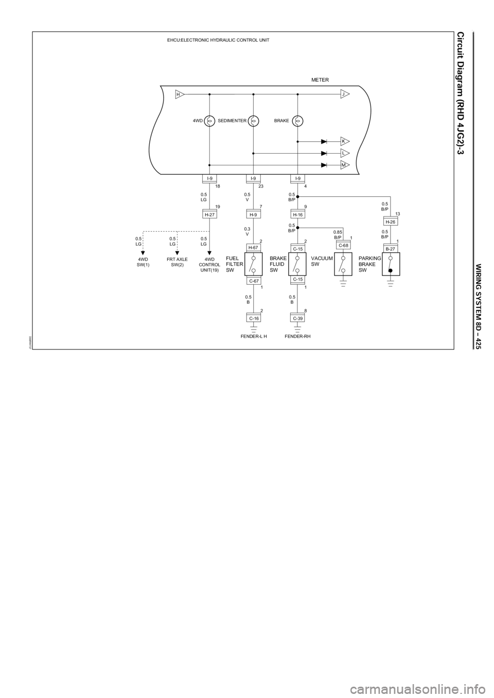
D08RW737
BRAKE EHCU:ELECTRONIC HYDRAULIC CONTROL UNIT
SEDIMENTER 4WD
BRAKE
FLUID
SWPARKING
BRAKE
SW
18
19
4WD
CONTROL
UNIT(19)
FRT AXLE
SW(2)4WD
SW(1)0.5
LG
0.5
LG 0.5
LG 0.5
LGI-9
H-2723
7
2 0.5
V
0.3
V0.5
B/P
0.85
B/P
0.5
B0.5
B/P0.5
B/P I-9
H-9
H-674
1
8 9
213
1
FENDER-RH0.5
B/PI-9
H-16
C-15
C-39 C-15FUEL
FILTER
SW
0.5
B1
2
FENDER-L HC-16 C-67
VACUUM
SW
1
C-68H-26
B-27
METER
Page 3026 of 6000
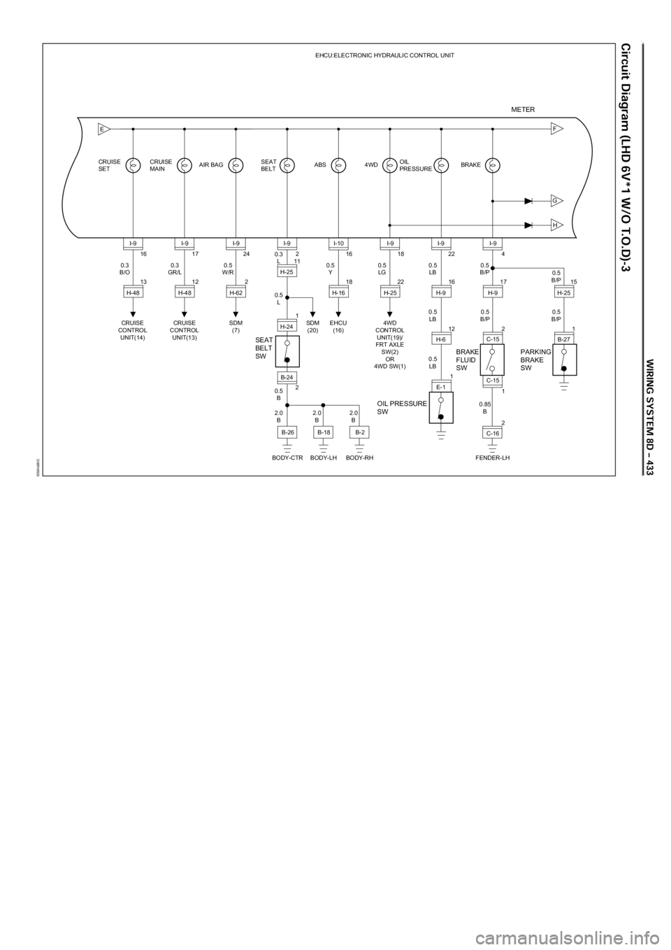
D08RW926
G
H
FE
16
13 CRUISE
SETCRUISE
MAINAIR BAG ABS 4WD BRAKEEHCU:ELECTRONIC HYDRAULIC CONTROL UNIT
OIL
PRESSURE
CRUISE
CONTROL
UNIT(14)0.3
B/OI-9
H-4817
12
CRUISE
CONTROL
UNIT(13) 0.3
GR/LI-9
H-4824
2
SDM
(7)SDM
(20) 0.5
W/RI-9
H-6216
18
EHCU
(16)
OIL PRESSURE
SWBRAKE
FLUID
SW SEAT
BELT
SWPARKING
BRAKE
SW
0.5
YI-10
H-1618
22
4WD
CONTROL
UNIT(19)/
FRT AXLE
SW(2)
OR
4WD SW(1)0.5
LGI-9
H-2522
16
12
1 0.5
LB
0.5
LB0.5
B/P
0.85
B0.5
B/P0.5
B/P
0.5
LBI-9
H-9
H-6
E-1
SEAT
BELT
2
11 0.3
L
0.5
L
2.0
B2.0
B2.0
B 0.5
BI-9
B-24 H-25
1
2 H-244
1
2 17
215
1
FENDER-LH0.5
B/PI-9
H-9
C-15
C-16
BODY-CTR BODY-LH BODY-RHB-26
B-18B-2C-15H-25
B-27
METER