1998 OPEL FRONTERA brake fluid
[x] Cancel search: brake fluidPage 5712 of 6000
7A–23 AUTOMATIC TRANSMISSION (4L30–E)
Stall Test
The stall test allows you to check the transmission for
internal abrasion and the one way clutch for slippage.
Torque converter performance can also be evaluated.
The stall test results together with the road test results will
identify transmission components requiring servicing or
adjustment.
Stall Test Procedure:
1. Check the level of the engine coolant, the engine oil,
and the automatic transmission fluid. Replenish if
necessary.
2. Block the wheels and set the parking brake.
3. Connect a tachometer to the engine.
4. Start the engine and allow it to idle until the engine
coolant temperature reaches 70 – 80
C (158 –
176
F).
5. Hold the brake pedal down as far as it will go.
6. Place the selector in the “D” range.
7. Gradually push the accelerator pedal to the floor.
The throttle valve will be fully open.
Note the engine speed at which the tachometer
needle stabilizes.
Stall Speed : 2,100
150 rpm
NOTE: Do not continuously run this test longer than 5
seconds.
8. Release the accelerator pedal.
9. Place the selector in the “N” range.
10. Run the engine at 1,200 rpm for one minute.
This will cool the transmission fluid.
11. Repeat Steps 7 – 10 for the “3”, “2”, “L” and “R”
ranges.
Line Pressure Test
The line pressure test checks oil pump and control valve
pressure regulator valve function. It will also detect oil
leakage.
Line Pressure Test Procedure:
1. Check the level of the engine coolant, the engine oil,
and the automatic transmission fluid.
Replenish if required.
2. Block the wheels and set the parking brake.
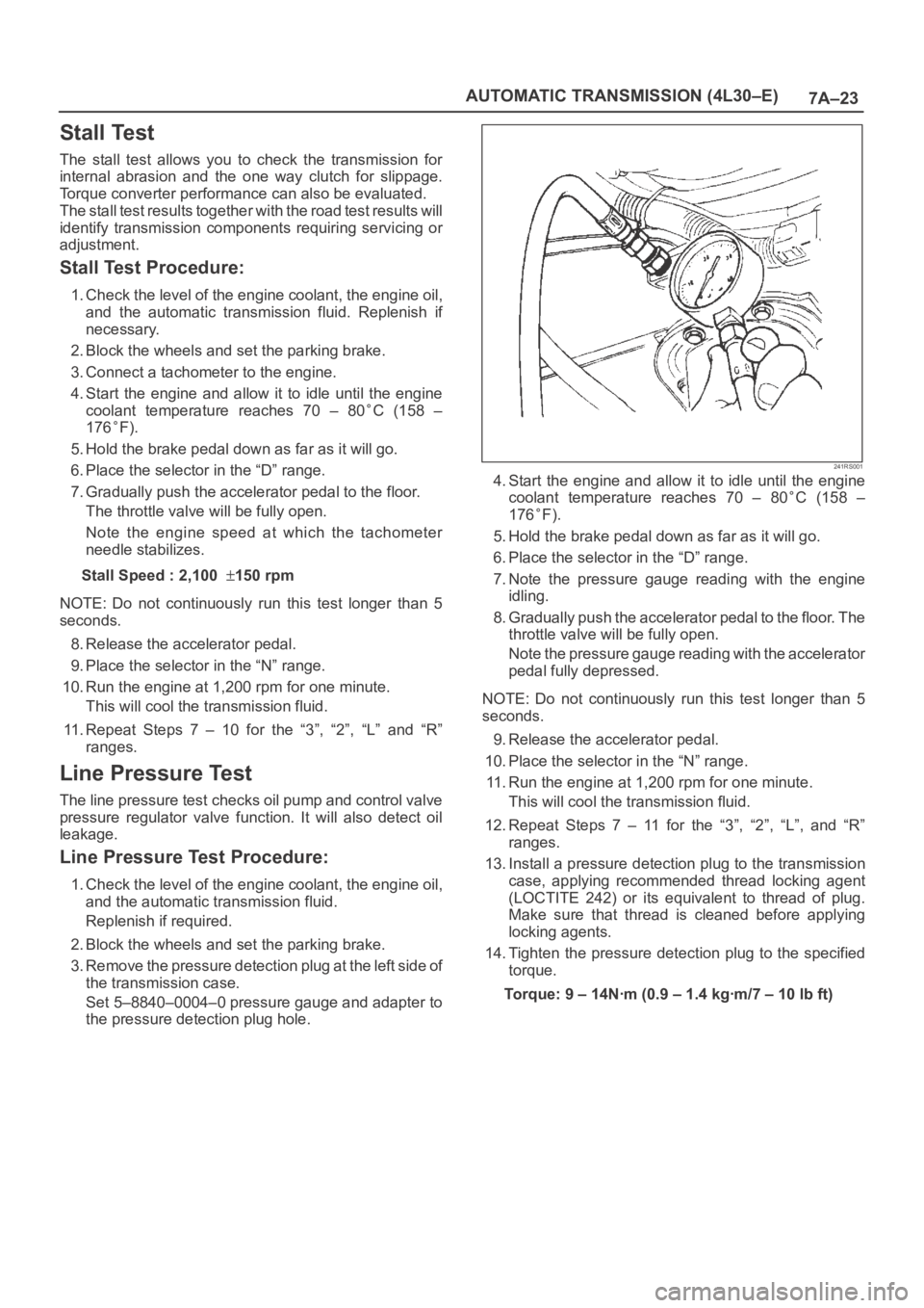
3. Remove the pressure detection plug at the left side of
the transmission case.
Set 5–8840–0004–0 pressure gauge and adapter to
the pressure detection plug hole.
241RS001
4. Start the engine and allow it to idle until the engine
coolant temperature reaches 70 – 80
C (158 –
176
F).
5. Hold the brake pedal down as far as it will go.
6. Place the selector in the “D” range.
7. Note the pressure gauge reading with the engine
idling.
8. Gradually push the accelerator pedal to the floor. The
throttle valve will be fully open.
Note the pressure gauge reading with the accelerator
pedal fully depressed.
NOTE: Do not continuously run this test longer than 5
seconds.
9. Release the accelerator pedal.
10. Place the selector in the “N” range.
11. Run the engine at 1,200 rpm for one minute.
This will cool the transmission fluid.
12. Repeat Steps 7 – 11 for the “3”, “2”, “L”, and “R”
ranges.
13. Install a pressure detection plug to the transmission
case, applying recommended thread locking agent
(LOCTITE 242) or its equivalent to thread of plug.
Make sure that thread is cleaned before applying
locking agents.
14. Tighten the pressure detection plug to the specified
torque.
Torque:9–14Nꞏm(0.9–1.4kgꞏm/7–10lbft)
Page 5735 of 6000
7A–46
AUTOMATIC TRANSMISSION (4L30–E)
Rear Oil Seal (Extension Housing)
Removal
1. Remove transfer case assembly from the vehicle.
Refer to Transfer Case in Drive Line/Axle section.
2. Remove rear oil seal from transmission extension
housing.
241RW005
Installation
1. Use 5–8840–2282–0 (J–36797) extension housing
oil seal installer, and install the rear oil seal to the
transmission extension housing.
2. Install the transfer case assembly to the vehicle.
Refer to Transfer Case in Drive Line/Axle section.
Transmission (4L30–E)
Disassembly
NOTE: During the disassembly and reassembly, perform
the following:
Wash each part thoroughly, and blow air through each
oil passage and groove to eliminate blockage.
Seal rings, roll pins, and gaskets should be replaced.
When assembling the components, apply
DEXRON
–III Automatic Transmission Fluid (ATF)
to each seal, rotating part, and sliding part.
Do not dip part facings, such as clutch or brake drive
plates, in cleaner when washing it.
Also, always coat parts with new ATF two or three
times after cleaning with solvent.
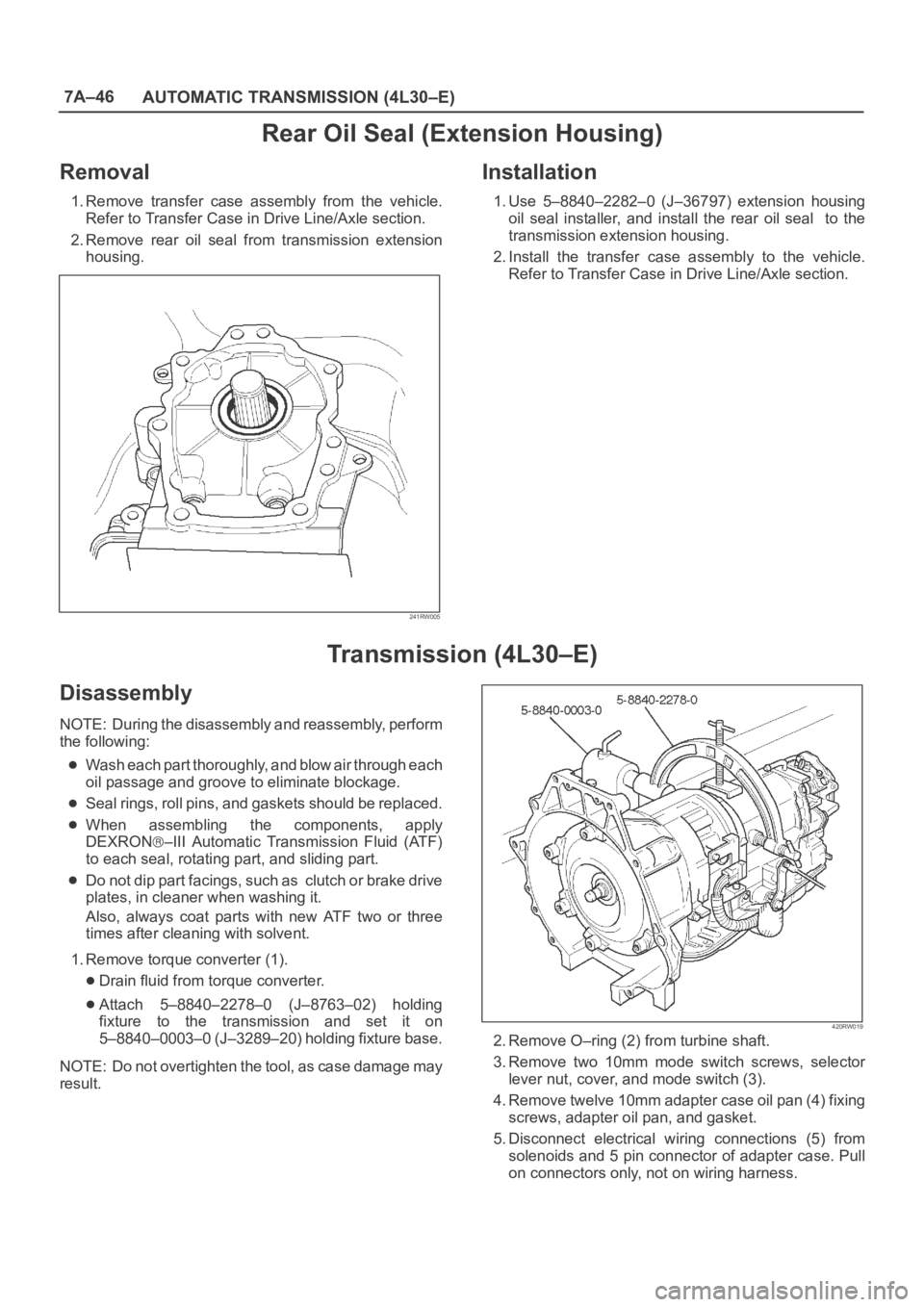
1. Remove torque converter (1).
Drain fluid from torque converter.
Attach 5–8840–2278–0 (J–8763–02) holding
fixture to the transmission and set it on
5–8840–0003–0 (J–3289–20) holding fixture base.
NOTE: Do not overtighten the tool, as case damage may
result.
420RW019
2. Remove O–ring (2) from turbine shaft.
3. Remove two 10mm mode switch screws, selector
lever nut, cover, and mode switch (3).
4. Remove twelve 10mm adapter case oil pan (4) fixing
screws, adapter oil pan, and gasket.
5. Disconnect electrical wiring connections (5) from
solenoids and 5 pin connector of adapter case. Pull
on connectors only, not on wiring harness.
Page 5782 of 6000

AUTOMATIC TRANSMISSION (AW30-40LE) 7A–1
SECTION 7A
CONTENTS
AUTOMATIC TRANSMISSION (AW30-40LE)
GENERAL DESCRIPTION . . . . . . . . . . . . . . . . . . . . . . . . . . . . . . . . . . . . . . . . . . . . . . . . . . . . . . . . . . . . . 7A–3
CONSTRUCTION . . . . . . . . . . . . . . . . . . . . . . . . . . . . . . . . . . . . . . . . . . . . . . . . . . . . . . . . . . . . . . . . . . . 7A–3
ELECTRONIC CONTROL COMPONENTS . . . . . . . . . . . . . . . . . . . . . . . . . . . . . . . . . . . . . . . . . . . . . . . 7A–4
TRANSMISSION CONTROL MODULE (TCM) . . . . . . . . . . . . . . . . . . . . . . . . . . . . . . . . . . . . . . . . . . . . 7A–5
CONTROL SYSTEM DIAGRAM. . . . . . . . . . . . . . . . . . . . . . . . . . . . . . . . . . . . . . . . . . . . . . . . . . . . . . . . 7A–6
CONTROL AND FUNCTIONS . . . . . . . . . . . . . . . . . . . . . . . . . . . . . . . . . . . . . . . . . . . . . . . . . . . . . . . . . 7A–7
MAJOR INPUT/OUTPUT COMPONENTS . . . . . . . . . . . . . . . . . . . . . . . . . . . . . . . . . . . . . . . . . . . . . . . . 7A–9
LOCATION OF CLUTCH, BRAKE ONE-WAY CLUTCH AND SOLENOID . . . . . . . . . . . . . . . . . . . . . . . 7A–10
OPERATION OF CLUTCH, BRAKE AND ONE-WAY CLUTCH . . . . . . . . . . . . . . . . . . . . . . . . . . . . . . . 7A–11
SPEED CHANGE AND LOCK-UP PATTERN . . . . . . . . . . . . . . . . . . . . . . . . . . . . . . . . . . . . . . . . . . . . . . 7A–11
OVERDRIVE AND LOCK-UP OPERATING CONDITIONS . . . . . . . . . . . . . . . . . . . . . . . . . . . . . . . . . . . 7A–12
DIAGNOSIS . . . . . . . . . . . . . . . . . . . . . . . . . . . . . . . . . . . . . . . . . . . . . . . . . . . . . . . . . . . . . . . . . . . . . . . . . 7A–13
BASIC TROUBLESHOOTING
. . . . . . . . . . . . . . . . . . . . . . . . . . . . . . . . . . . . . . . . . . . . . . . . 7A–13
SELF-DIAGNOSIS . . . . . . . . . . . . . . . . . . . . . . . . . . . . . . . . . . . . . . . . . . . . . . . . . . . . . . . . . . . . . . . . . . 7A–14
DIAGNOSIS WITH TECH2 . . . . . . . . . . . . . . . . . . . . . . . . . . . . . . . . . . . . . . . . . . . . . . . . . . . . . . . . . . . . 7A–17
TECH2 CONNECTION . . . . . . . . . . . . . . . . . . . . . . . . . . . . . . . . . . . . . . . . . . . . . . . . . . . . . . . . . . . . . . . 7A–18
TECH2 OPERATING FLOW CHART (START UP) . . . . . . . . . . . . . . . . . . . . . . . . . . . . . . . . . . . . . . . . . 7A–19
TRANSMISSION DATA . . . . . . . . . . . . . . . . . . . . . . . . . . . . . . . . . . . . . . . . . . . . . . . . . . . . . . . . . . . . . . 7A–21
TCC DATA . . . . . . . . . . . . . . . . . . . . . . . . . . . . . . . . . . . . . . . . . . . . . . . . . . . . . . . . . . . . . . . . . . . . . . . . 7A–22
INTERMITTENT CONDITIONS . . . . . . . . . . . . . . . . . . . . . . . . . . . . . . . . . . . . . . . . . . . . . . . . . . . . . . . . 7A–23
IDENTIFICATION OF TRANSMISSION CONTROL MODULE (TCM) . . . . . . . . . . . . . . . . . . . . . . . . . . . 7A–24
DIAGNOSTIC TROUBLE CODES (DTC) CHECK . . . . . . . . . . . . . . . . . . . . . . . . . . . . . . . . . . . . . . . . . . 7A–25
WIRING DIAGRAM . . . . . . . . . . . . . . . . . . . . . . . . . . . . . . . . . . . . . . . . . . . . . . . . . . . . . . . . . . . . . . . . . 7A–52
CONNECTOR LIST . . . . . . . . . . . . . . . . . . . . . . . . . . . . . . . . . . . . . . . . . . . . . . . . . . . . . . . . . . . . . . . . . 7A–54
TROUBLESHOOTING CHART . . . . . . . . . . . . . . . . . . . . . . . . . . . . . . . . . . . . . . . . . . . . . . . . . . . . . . . . 7A–56
MANUAL SHIFTING TEST . . . . . . . . . . . . . . . . . . . . . . . . . . . . . . . . . . . . . . . . . . . . . . . . . . . . . . . . . . . . 7A–62
STALL TEST . . . . . . . . . . . . . . . . . . . . . . . . . . . . . . . . . . . . . . . . . . . . . . . . . . . . . . . . . . . . . . . . . . . . . . . 7A–63
TIME LAG TEST . . . . . . . . . . . . . . . . . . . . . . . . . . . . . . . . . . . . . . . . . . . . . . . . . . . . . . . . . . . . . . . . . . . . 7A–64
HYDRAULIC TEST . . . . . . . . . . . . . . . . . . . . . . . . . . . . . . . . . . . . . . . . . . . . . . . . . . . . . . . . . . . . . . . . . . 7A–65
ROAD TEST . . . . . . . . . . . . . . . . . . . . . . . . . . . . . . . . . . . . . . . . . . . . . . . . . . . . . . . . . . . . . . . . . . . . . . . 7A–66
SHIFT POINT CHART AND LOCK-UP POINT CHART . . . . . . . . . . . . . . . . . . . . . . . . . . . . . . . . . . . . . . 7A–69
TCM VOLTAGE CHECK . . . . . . . . . . . . . . . . . . . . . . . . . . . . . . . . . . . . . . . . . . . . . . . . . . . . . . . . . . . . . . 7A–71
TCM STANDARD VOLTAGE . . . . . . . . . . . . . . . . . . . . . . . . . . . . . . . . . . . . . . . . . . . . . . . . . . . . . . . . . . 7A–72
ON-VEHICLE SERVICE . . . . . . . . . . . . . . . . . . . . . . . . . . . . . . . . . . . . . . . . . . . . . . . . . . . . . . . . . . . . . . . 7A–75
TRANSIMISSION FLUID LEVEL AND CONDITION . . . . . . . . . . . . . . . . . . . . . . . . . . . . . . . . . . . . . . . . 7A–75
ATF REPLACEMENT . . . . . . . . . . . . . . . . . . . . . . . . . . . . . . . . . . . . . . . . . . . . . . . . . . . . . . . . . . . . . . . . 7A–75
NEUTRAL START SWITCH INSPECTION. . . . . . . . . . . . . . . . . . . . . . . . . . . . . . . . . . . . . . . . . . . . . . . . 7A–76
BRAKE SIGNAL INSPECTION . . . . . . . . . . . . . . . . . . . . . . . . . . . . . . . . . . . . . . . . . . . . . . . . . . . . . . . . 7A–77
VEHICLE SPEED SENSOR INSPECTION . . . . . . . . . . . . . . . . . . . . . . . . . . . . . . . . . . . . . . . . . . . . . . . 7A–77
INPUT AND OUTPUT REVOLUTION SENSOR INSPECTION . . . . . . . . . . . . . . . . . . . . . . . . . . . . . . . . 7A–77
PATTERN SELECT SWITCH INSPECTION . . . . . . . . . . . . . . . . . . . . . . . . . . . . . . . . . . . . . . . . . . . . . . . 7A–78
OVERDRIVE OFF SWITCH INSPECTION . . . . . . . . . . . . . . . . . . . . . . . . . . . . . . . . . . . . . . . . . . . . . . . 7A–78
SOLENOID INSPECTION . . . . . . . . . . . . . . . . . . . . . . . . . . . . . . . . . . . . . . . . . . . . . . . . . . . . . . . . . . . . 7A–78
THROTTLE POSITION SENSOR INSPECTION . . . . . . . . . . . . . . . . . . . . . . . . . . . . . . . . . . . . . . . . . . . 7A–79
ATF TEMPERATURE SENSOR INSPECTION. . . . . . . . . . . . . . . . . . . . . . . . . . . . . . . . . . . . . . . . . . . . . 7A–79
SELECTOR LEVER . . . . . . . . . . . . . . . . . . . . . . . . . . . . . . . . . . . . . . . . . . . . . . . . . . . . . . . . . . . . . . . . . 7A–80
TRANSMISSION CONTROL MODULE (TCM) . . . . . . . . . . . . . . . . . . . . . . . . . . . . . . . . . . . . . . . . . . . . 7A–81
SHIFT SOLENOID AND LOCK-UP SOLENOID. . . . . . . . . . . . . . . . . . . . . . . . . . . . . . . . . . . . . . . . . . . . 7A–83
Page 5844 of 6000
AUTOMATIC TRANSMISSION (AW30-40LE) 7A–63
F07RY00002
STALL TEST
The object of this test is to check the overall performance of the
transmission and engine by measuring the maximum engine
speeds at the "D" and "R" ranges.
NOTE:
(1) Perform the test at normal operation fluid temperature
(50 – 80
C or 122 – 176F).
(2) Do not continuously run this test longer than 5
seconds.
MEASURE STALL SPEED
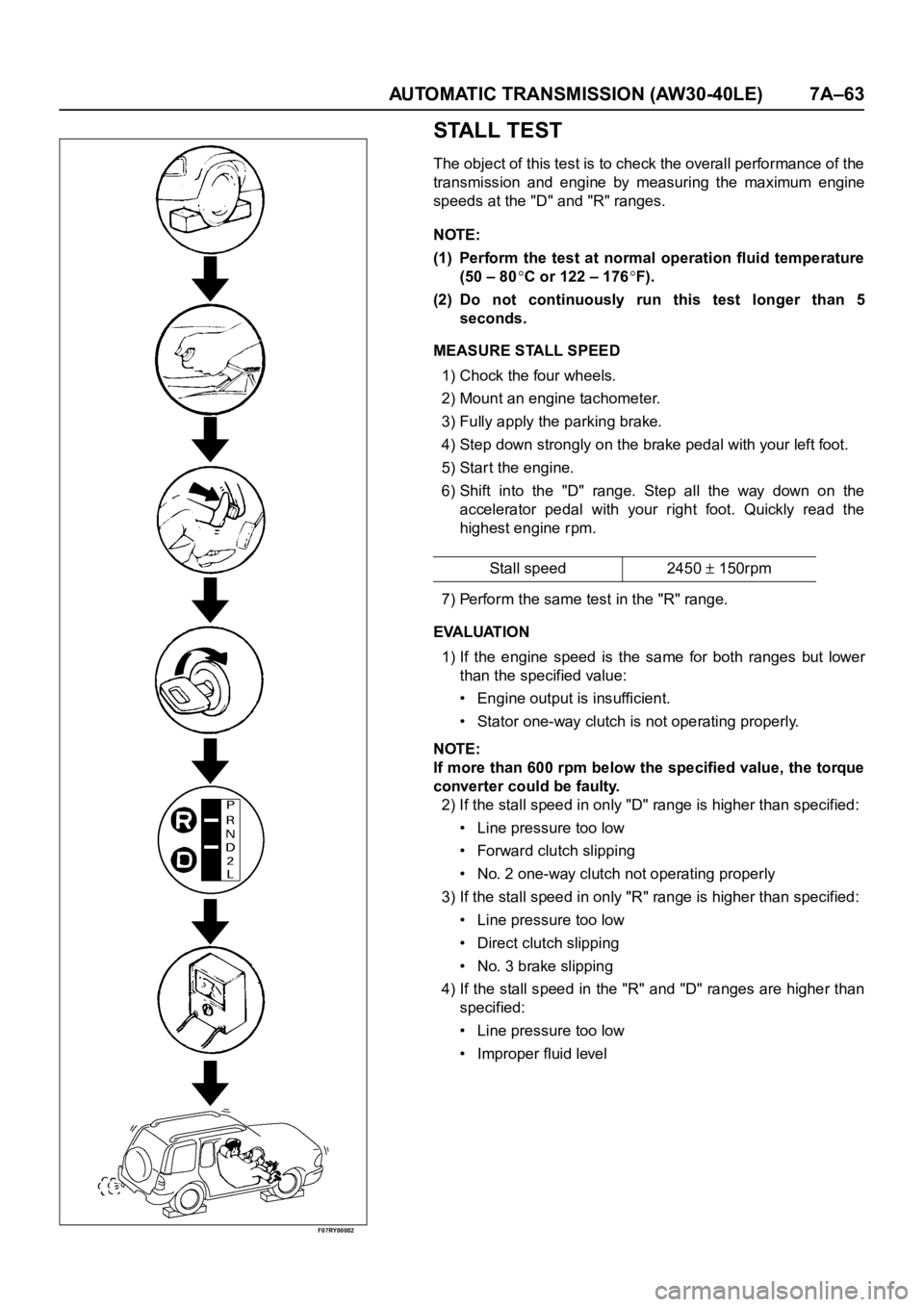
1) Chock the four wheels.
2) Mount an engine tachometer.
3) Fully apply the parking brake.
4) Step down strongly on the brake pedal with your left foot.
5) Star t the engine.
6) Shift into the "D" range. Step all the way down on the
accelerator pedal with your right foot. Quickly read the
highest engine rpm.
7) Perform the same test in the "R" range.
EVALUATION
1) If the engine speed is the same for both ranges but lower
than the specified value:
• Engine output is insufficient.
• Stator one-way clutch is not operating properly.
NOTE:
If more than 600 rpm below the specified value, the torque
converter could be faulty.
2) If the stall speed in only "D" range is higher than specified:
• Line pressure too low
• Forward clutch slipping
• No. 2 one-way clutch not operating properly
3) If the stall speed in only "R" range is higher than specified:
• Line pressure too low
• Direct clutch slipping
• No. 3 brake slipping
4) If the stall speed in the "R" and "D" ranges are higher than
specified:
• Line pressure too low
• Improper fluid levelStall speed 2450
150rpm
Page 5845 of 6000
7A–64 AUTOMATIC TRANSMISSION (AW30-40LE)
F07RY00003
TIME LAG TEST
If the shift lever is shifted while the engine is idling, there will be
a cer tain time elapse or lag before the shock can be felt. This is
used for checking the condition of the forward clutch, direct
clutch, No. 3 brake, and No. 2 one-way clutch.
NOTE:
(1) Perform the test at normal operation fluid temperature
(50 – 80
C or 122 – 176F).
(2) Be sure to allow one minute interval between tests.
(3) Make three measurements and take the average value.
MEASURE TIME LAG
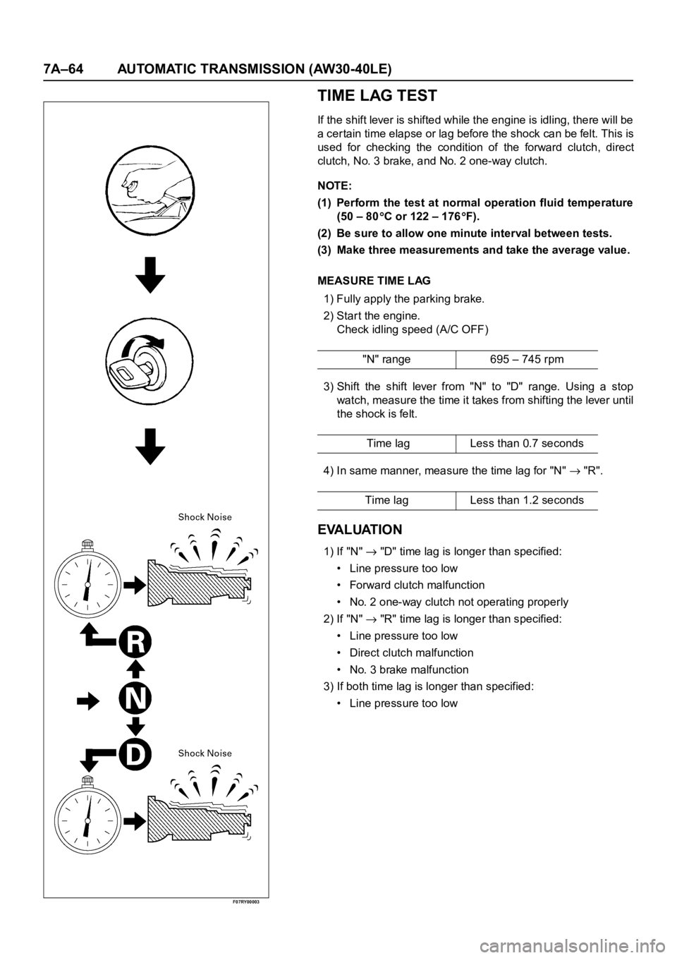
1) Fully apply the parking brake.
2) Start the engine.
Check idling speed (A/C OFF)
3) Shift the shift lever from "N" to "D" range. Using a stop
watch, measure the time it takes from shifting the lever until
the shock is felt.
4) In same manner, measure the time lag for "N"
"R".
EVALUATION
1) If "N" "D" time lag is longer than specified:
• Line pressure too low
• Forward clutch malfunction
• No. 2 one-way clutch not operating properly
2) If "N"
"R" time lag is longer than specified:
• Line pressure too low
• Direct clutch malfunction
• No. 3 brake malfunction
3) If both time lag is longer than specified:
• Line pressure too low"N" range 695 – 745 rpm
Time lag Less than 0.7 seconds
Time lag Less than 1.2 seconds
Page 5846 of 6000
AUTOMATIC TRANSMISSION (AW30-40LE) 7A–65
F07RY00004
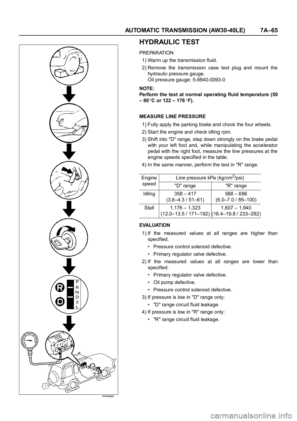
HYDRAULIC TEST
PREPARATION
1) Warm up the transmission fluid.
2) Remove the transmission case test plug and mount the
hydraulic pressure gauge.
Oil pressure gauge: 5-8840-0093-0
NOTE:
Perform the test at normal operating fluid temperature (50
– 80
C or 122 – 176F).
MEASURE LINE PRESSURE
1) Fully apply the parking brake and chock the four wheels.
2) Start the engine and check idling rpm.
3) Shift into "D" range, step down strongly on the brake pedal
with your left foot and, while manipulating the accelerator
pedal with the right foot, measure the line pressures at the
engine speeds specified in the table.
4) In the same manner, perform the test in "R" range.
EVALUATION
1) If the measured values at all ranges are higher than
specified.
• Pressure control solenoid defective.
• Primary regulator valve defective.
2) If the measured values at all ranges are lower than
specified.
• Primary regulator valve defective.
• Oil pump defective.
• Pressure control solenoid defective.
3) If pressure is low in "D" range only:
• "D" range circuit fluid leakage.
4) If pressure is low in "R" range only:
• "R" range circuit fluid leakage. Engine
speedLine pressure kPa (kg/cm
2/psi)
"D" range "R" range
Idling 358 – 417
(3.6–4.3 / 51–61)588 – 686
(6.0–7.0 / 85–100)
Stall 1,176 – 1,323
(12.0–13.5 / 171–192)1,607 – 1,940
(16.4–19.8 / 233–282)
Page 5856 of 6000

AUTOMATIC TRANSMISSION (AW30-40LE) 7A–75
ON-VEHICLE SERVICE
242RX00001
TRANSIMISSION FLUID LEVEL AND
CONDITION
Park vehicle on level ground and set parking brake.
With the engine idling, move the shift lever through all
positions from "P" to "L", then return to position "P".
Check to see If the level of fluid comes to "HOT" range
of about 80
C (176F) on the dipstick gauge.
If the level of fluid is too low, replenish to bring it to
maximum level in "HOT" range.
Inspection of fluid condition
If the ATF is black or smells burnt, replace it.
ATF REPLACEMENT
NOTE:
Do not overfill.
1) Remove the drain plug from oil pan and drain the
fluid.
2) Reinstall the drain plug securely.
3) With the engine OFF, add new fluid through the filler
tube.
4) Star t the engine and shift the selector into all
position from "P" through "L", and then shift into "P".
5) With the engine idling, check the fluid level. Add fluid
up to the "COLD" level on the dipstick.
6) The ATF level must be checked again for correct
level with the "HOT" level.
NOTE:
To prevent fluid leaks, the drain plug gasket must be
replaced each time this plug is removed.
Tr a n s m i s s i o n
Drain and refill 5.2 L
Dry fill 8.7 L
Fluid BESCO ATF III
Page 5888 of 6000

AUTOMATIC TRANSMISSION (AW30-40LE) 7A–107
DISASSEMBLY, INSPECTION AND
REASSEMBLY OF MINOR COMPONENTS
The instructions here are organized so that you work on only
one component group at a time.
This will help avoid confusion from similar-looking parts of
different subassemblies being on your workbench at the same
time.
The component groups are inspected and repaired from the
converter housing side.
As much as possible, complete the inspection, repair and
reassembly before proceeding to the next component group. If
a component group cannot be reassembled because parts are
being ordered, be sure to keep all parts of that group in a
separate container while proceeding with disassembly,
inspection, repair and reassembly of other component groups.
Recommended ATF type BESCO ATF II or III.
GENERAL CLEANING NOTES:
1. All disassembled parts should be washed clean and any
fluid passages and holes blown through with compressed
air.
2. When using compressed air to dry parts, always aim away
from yourself to prevent accidentally spraying automatic
transmission fluid in your face.
3. The recommended automatic transmission fluid should be
used for cleaning.
PARTS ARRANGEMENT:
1. After cleaning, the par ts should be arranged in proper order
to allow performing inspection, repairs, and reassembly
with efficiency.
2. When disassembling a valve body, be sure to keep each
valve together with the corresponding spring.
3. New brakes and clutches that are to be used for
replacement must be soaked in transmission fluid for at
least thir ty before assembly.
GENERAL ASSEMBLY:
1. All oil seal rings, clutch discs, clutch plates, rotating parts,
and sliding surfaces should be coated with transmission
fluid prior to reassembly.
2. All gaskets and rubber O-rings should be replaced.
3. Make sure that ends of a snap ring are not aligned with one
of the cutouts and are installed in the groove correctly.
4. If a worn bushing is to be replaced, the subassembly
containing that bushing must be replaced.
5.Check thrust bearings and races for wear or damage.
Replace if necessary.
6. Use petroleum jelly or vaseline to keep par ts in place.