Page 4039 of 6000

4A2B–32DIFFERENTIAL (REAR 244mm)
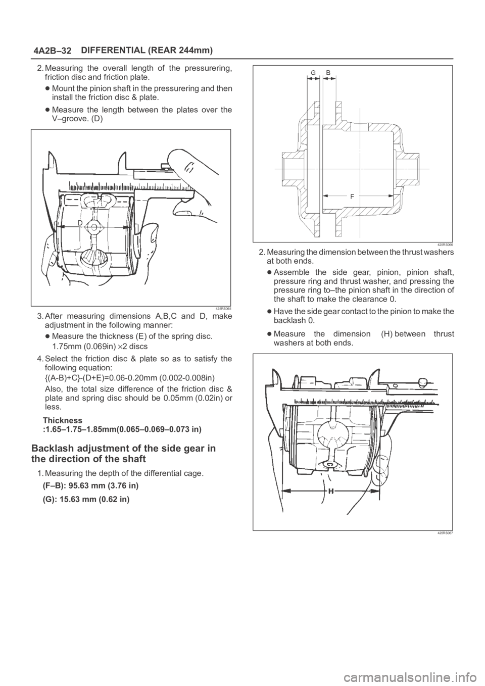
2. Measuring the overall length of the pressurering,
friction disc and friction plate.
Mount the pinion shaft in the pressurering and then
install the friction disc & plate.
Measure the length between the plates over the
V–groove. (D)
425RS065
3. After measuring dimensions A,B,C and D, make
adjustment in the following manner:
Measure the thickness (E) of the spring disc.
1.75mm (0.069in)
2discs
4. Select the friction disc & plate so as to satisfy the
following equation:
{(A-B)+C}-(D+E)=0.06-0.20mm (0.002-0.008in)
Also, the total size difference of the friction disc &
plate and spring disc should be 0.05mm (0.02in) or
less.
Thickness
:1.65–1.75–1.85mm(0.065–0.069–0.073 in)
Backlash adjustment of the side gear in
the direction of the shaft
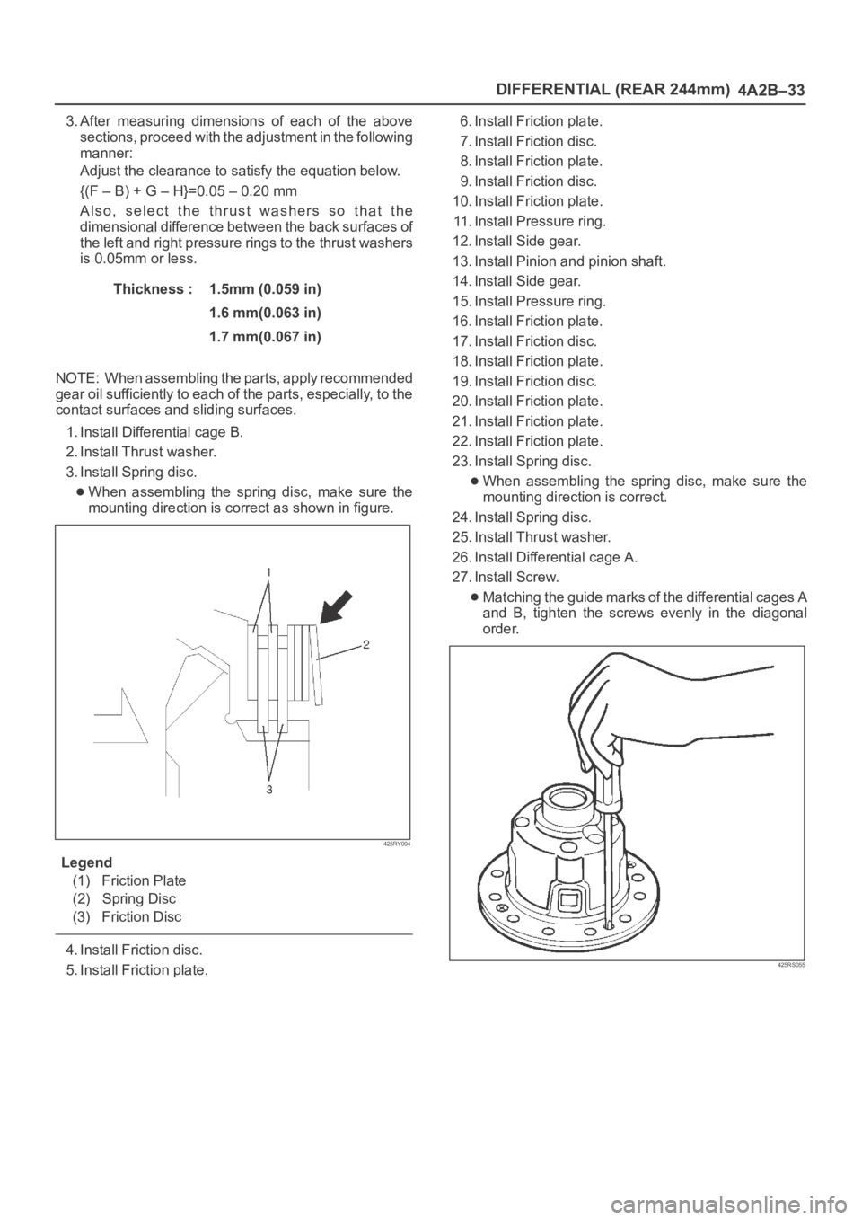
1. Measuring the depth of the differential cage.
(F–B): 95.63 mm (3.76 in)
(G): 15.63 mm (0.62 in)
425RS066
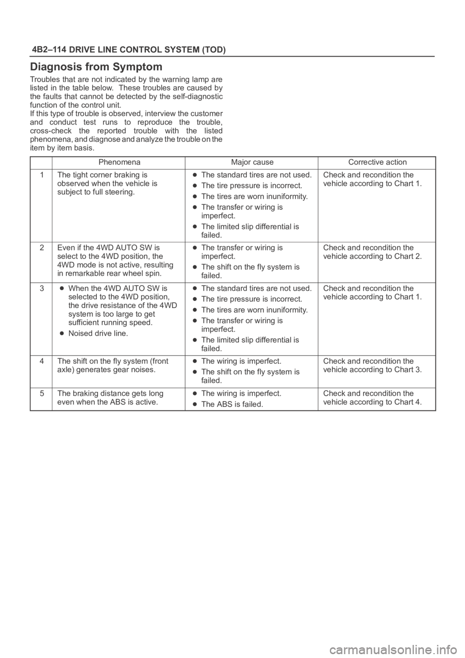
2. Measuring the dimension between the thrust washers
at both ends.
Assemble the side gear, pinion, pinion shaft,
pressure ring and thrust washer, and pressing the
pressure ring to–the pinion shaft in the direction of
the shaft to make the clearance 0.
Have the side gear contact to the pinion to make the
backlash 0.
Measure the dimension (H) between thrust
washers at both ends.
425RS067
Page 4040 of 6000

DIFFERENTIAL (REAR 244mm)
4A2B–33
3. After measuring dimensions of each of the above
sections, proceed with the adjustment in the following
manner:
Adjust the clearance to satisfy the equation below.
{(F – B) + G – H}=0.05 – 0.20 mm
Also, select the thrust washers so that the
dimensional difference between the back surfaces of
the left and right pressure rings to the thrust washers
is 0.05mm or less.
Thickness : 1.5mm (0.059 in)
1.6 mm(0.063 in)
1.7 mm(0.067 in)
NOTE: When assembling the parts, apply recommended
gear oil sufficiently to each of the parts, especially, to the
contact surfaces and sliding surfaces.
1. Install Differential cage B.
2. Install Thrust washer.
3. Install Spring disc.
When assembling the spring disc, make sure the
mounting direction is correct as shown in figure.
425RY004
Legend
(1) Friction Plate
(2) Spring Disc
(3) Friction Disc
4. Install Friction disc.
5. Install Friction plate.6. Install Friction plate.
7. Install Friction disc.
8. Install Friction plate.
9. Install Friction disc.
10. Install Friction plate.
11. Install Pressure ring.
12. Install Side gear.
13. Install Pinion and pinion shaft.
14. Install Side gear.
15. Install Pressure ring.
16. Install Friction plate.
17. Install Friction disc.
18. Install Friction plate.
19. Install Friction disc.
20. Install Friction plate.
21. Install Friction plate.
22. Install Friction plate.
23. Install Spring disc.
When assembling the spring disc, make sure the
mounting direction is correct.
24. Install Spring disc.
25. Install Thrust washer.
26. Install Differential cage A.
27. Install Screw.
Matching the guide marks of the differential cages A
and B, tighten the screws evenly in the diagonal
order.
425RS055
Page 4041 of 6000
4A2B–34DIFFERENTIAL (REAR 244mm)
28. Check the operation.
Measure the starting torque using the side gear
holder.
Starting torque:
29–45Nꞏm(3.0–4.6kgꞏm/22–33Ibft)
425RW065
Legend
(1) Side Gear Holder : 5–8840–2381–0
Page 4042 of 6000
DIFFERENTIAL (REAR 244mm)
4A2B–35
Main Data and Specifications
General Specifications
Rear axle
Ty p eBanjo, Semi–floating
Rear axle Size244 mm (9.61 in)
Gear typeHypoid
Gear ratio (to 1)4.100(6VE1 with A/T)
4.300(6VE1 with M/T,4JX1)
Differential typePinion (STD), Four pinion (LSD)
Lubricant GradeGL–5: (Standard differential)
GL–5, LSD: (Limited slip differential)
Locking Differential Lubricant80W90 GL–5 Limited Slip Differential Gear Lubricant
together with Limited Slip Differential Lubricant Additive
(Part No. 8–01052–358–0) or equivalent.
Capacity3.0 liter (2.6 Imp qt/3.2 US qt)
Page 4043 of 6000
4A2B–36DIFFERENTIAL (REAR 244mm)
Torque Specifications
420RY00002
Page 4044 of 6000
DIFFERENTIAL (REAR 244mm)
4A2B–37
Special Tools
ILLUSTRATIONTOOL NO.
TOOL NAME
5–8840–2294–0
(J–39210)
Installer; Axle shaft inner
seal
5–8840–0133–0
(J–8614–01)
Pinion flange holder
5–8840–2165–0
(J–37263)
Installer; Pinion oil seal
5–8840–2029–0
(J–42832)
Holding fixture
5–8840–0003–0
(J–3289–20)
Holding fixture base
5–8840–2587–0
(J–42379)
Remover; Bearing
ILLUSTRATIONTOOL NO.
TOOL NAME
5–8840–2576–0
(J–8107–3)
Adapter; Side bearing
plug
5–8840–2689–0
(J–44461)
Installer; Outer bearing
outer race
5–8840–0007–0
(J–8092)
Grip
5–8840–2690–0
(J–44462)
Installer; Inner bearing
outer race
5–8840–2681–0
(J–42824)
Pilot;Outer
5–8840–0127–0
(J–21777–43)
Nut & Bolt
Page 4045 of 6000
4A2B–38DIFFERENTIAL (REAR 244mm)
ILLUSTRATIONTOOL NO.
TOOL NAME
5–8840–2680–0
(J–44453)
Pilot; Inner
5–8840–2681
(J–44449)
Pilot; Outer bearing
5–8840–2678–0
(J–44451)
Gage plate
5–8840–0126–0
(J–8001)
Dial indicator
5–8840–2679–0
(J–44452)
Disc (2 required)
5–8840–0128–0
(J–23597–1)
Arbor
ILLUSTRATIONTOOL NO.
TOOL NAME
5–8840–2574–0
(J–42828)
Installer; Pinion bearing
5–8840–2293–0
(J–39209)
Punch; End nut lock
5–8840–2570–0
(J–42829)
Installer; Side bearing
5–8840–2323–0
(J–39602)
Remover; Outer bearing
5–8840–2586–0
(J–39858)
Clutch pack unloading
tool kit Includes
Screw cap, Cap and
Forcing screw
Page 4197 of 6000

DRIVE LINE CONTROL SYSTEM (TOD) 4B2–114
Diagnosis from Symptom
Troubles that are not indicated by the warning lamp are
listed in the table below. These troubles are caused by
the faults that cannot be detected by the self-diagnostic
function of the control unit.
If this type of trouble is observed, interview the customer
and conduct test runs to reproduce the trouble,
cross-check the reported trouble with the listed
phenomena, and diagnose and analyze the trouble on the
item by item basis.
PhenomenaMajor causeCorrective action
1The tight corner braking is
observed when the vehicle is
subject to full steering.The standard tires are not used.
The tire pressure is incorrect.
The tires are worn inuniformity.
The transfer or wiring is
imperfect.
The limited slip differential is
failed.
Check and recondition the
vehicle according to Chart 1.
2Even if the 4WD AUTO SW is
select to the 4WD position, the
4WD mode is not active, resulting
in remarkable rear wheel spin.The transfer or wiring is
imperfect.
The shift on the fly system is
failed.
Check and recondition the
vehicle according to Chart 2.
3When the 4WD AUTO SW is
selected to the 4WD position,
the drive resistance of the 4WD
system is too large to get
sufficient running speed.
Noised drive line.
The standard tires are not used.
The tire pressure is incorrect.
The tires are worn inuniformity.
The transfer or wiring is
imperfect.
The limited slip differential is
failed.
Check and recondition the
vehicle according to Chart 1.
4The shift on the fly system (front
axle) generates gear noises.The wiring is imperfect.
The shift on the fly system is
failed.
Check and recondition the
vehicle according to Chart 3.
5The braking distance gets long
even when the ABS is active.The wiring is imperfect.
The ABS is failed.
Check and recondition the
vehicle according to Chart 4.