1998 OPEL FRONTERA engine
[x] Cancel search: enginePage 5848 of 6000
AUTOMATIC TRANSMISSION (AW30-40LE) 7A–67
F07RY00007
F07RY00008
F07RY00009
F07RY00010
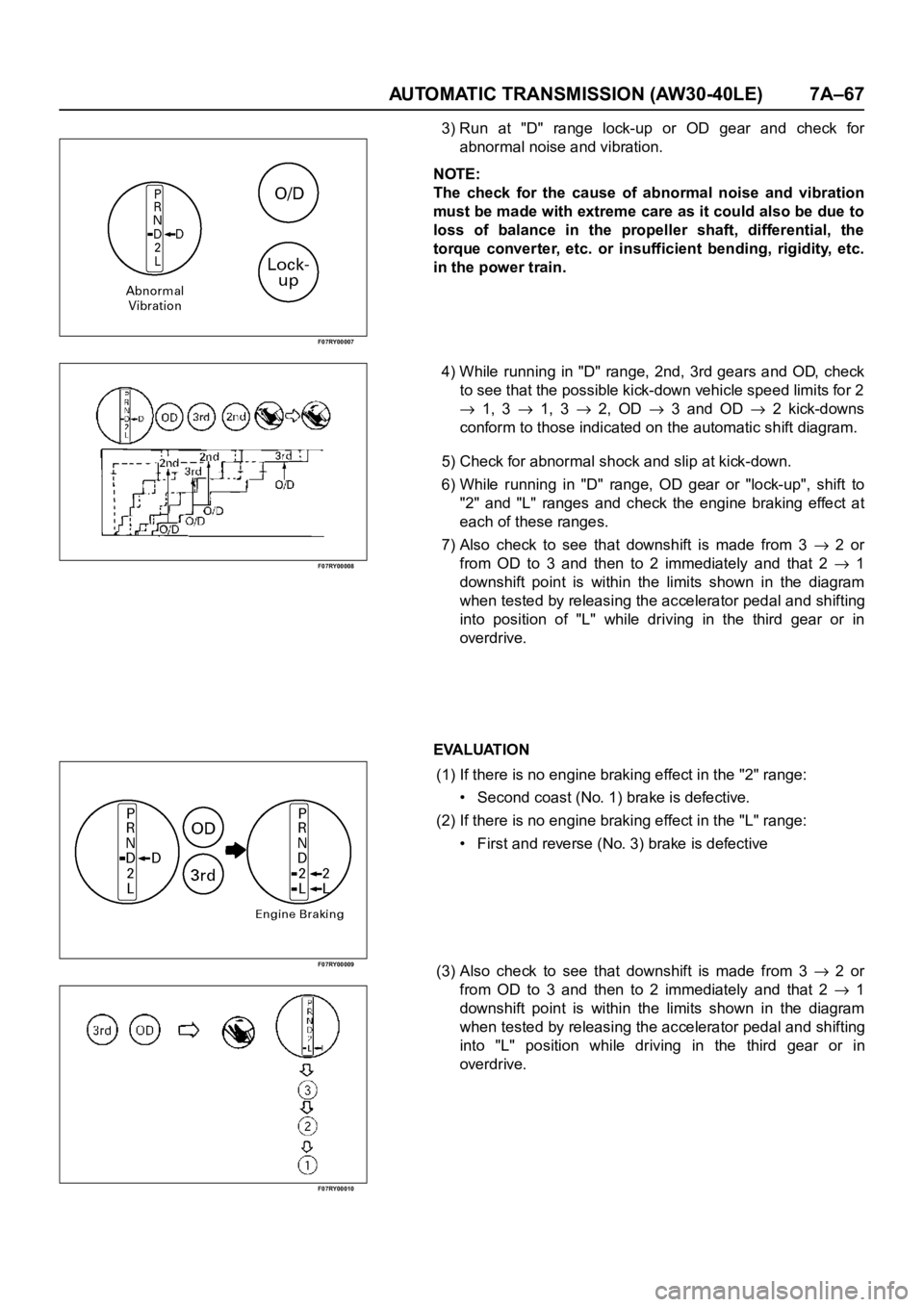
3) Run at "D" range lock-up or OD gear and check for
abnormal noise and vibration.
NOTE:
The check for the cause of abnormal noise and vibration
must be made with extreme care as it could also be due to
loss of balance in the propeller shaft, differential, the
torque converter, etc. or insufficient bending, rigidity, etc.
in the power train.
4) While running in "D" range, 2nd, 3rd gears and OD, check
to see that the possible kick-down vehicle speed limits for 2
1, 3 1, 3 2, OD 3 and OD 2 kick-downs
conform to those indicated on the automatic shift diagram.
5) Check for abnormal shock and slip at kick-down.
6) While running in "D" range, OD gear or "lock-up", shift to
"2" and "L" ranges and check the engine braking effect at
each of these ranges.
7) Also check to see that downshift is made from 3
2 or
from OD to 3 and then to 2 immediately and that 2
1
downshift point is within the limits shown in the diagram
when tested by releasing the accelerator pedal and shifting
into position of "L" while driving in the third gear or in
overdrive.
EVALUATION
(1) If there is no engine braking effect in the "2" range:
• Second coast (No. 1) brake is defective.
(2) If there is no engine braking effect in the "L" range:
• First and reverse (No. 3) brake is defective
(3) Also check to see that downshift is made from 3
2 or
from OD to 3 and then to 2 immediately and that 2
1
downshift point is within the limits shown in the diagram
when tested by releasing the accelerator pedal and shifting
into "L" position while driving in the third gear or in
overdrive.
Page 5849 of 6000
7A–68 AUTOMATIC TRANSMISSION (AW30-40LE)
F07RY00011
F07RY00012
F07RY00020
F07RY00014
F07RY00015
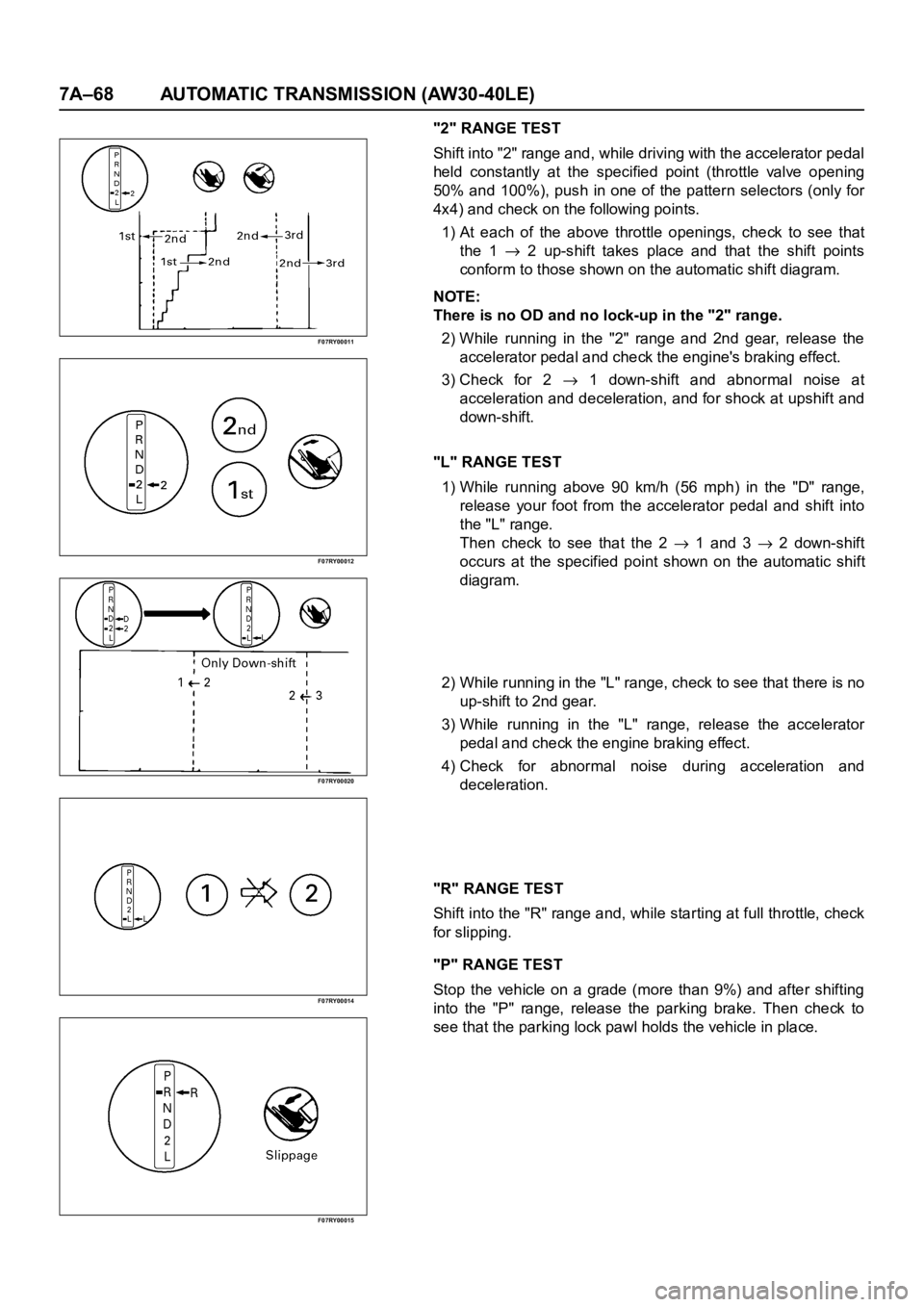
"2" RANGE TEST
Shift into "2" range and, while driving with the accelerator pedal
held constantly at the specified point (throttle valve opening
50% and 100%), push in one of the pattern selectors (only for
4x4) and check on the following points.
1) At each of the above throttle openings, check to see that
the 1
2 up-shift takes place and that the shift points
conform to those shown on the automatic shift diagram.
NOTE:
There is no OD and no lock-up in the "2" range.
2) While running in the "2" range and 2nd gear, release the
accelerator pedal and check the engine's braking effect.
3) Check for 2
1 down-shift and abnormal noise at
acceleration and deceleration, and for shock at upshift and
down-shift.
"L" RANGE TEST
1) While running above 90 km/h (56 mph) in the "D" range,
release your foot from the accelerator pedal and shift into
the "L" range.
Then check to see that the 2
1 and 3 2 down-shift
occurs at the specified point shown on the automatic shift
diagram.
2) While running in the "L" range, check to see that there is no
up-shift to 2nd gear.
3) While running in the "L" range, release the accelerator
pedal and check the engine braking effect.
4) Check for abnormal noise during acceleration and
deceleration.
"R" RANGE TEST
Shift into the "R" range and, while starting at full throttle, check
for slipping.
"P" RANGE TEST
Stop the vehicle on a grade (more than 9%) and after shifting
into the "P" range, release the parking brake. Then check to
see that the parking lock pawl holds the vehicle in place.
Page 5852 of 6000
AUTOMATIC TRANSMISSION (AW30-40LE) 7A–71
826RY00017
TCM VOLTAGE CHECK
TCM voltage check is done to check for transmission and
transmission control module (TCM) problems which cannot be
detected by self-diagnosis.
Additionally, it serves as a back-up check for self-diagnosis.
Measure the voltage drop and make a continuity test for each
of the sensors, solenoids, and switches.
If the voltage is within the specified range and continuity exists,
that particular area of the TCM and automatic transmission
assembly is normal.
If voltage deviation or lack of continuity is discovered,
disconnect the applicable parts and check each of them
individually.
This will allow you to determine the trouble location (TCM,
automatic transmission unit, or another area of the vehicle).
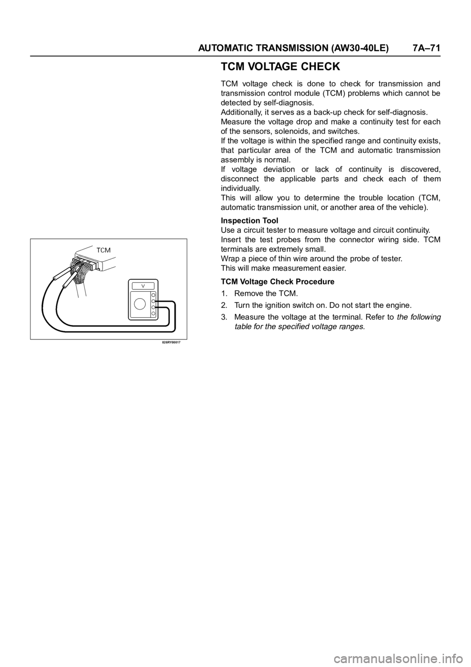
Inspection Tool
Use a circuit tester to measure voltage and circuit continuity.
Inser t the test probes from the connector wiring side. TCM
terminals are extremely small.
Wrap a piece of thin wire around the probe of tester.
This will make measurement easier.
TCM Voltage Check Procedure
1. Remove the TCM.
2. Turn the ignition switch on. Do not start the engine.
3. Measure the voltage at the terminal. Refer to
the following
table for the specified voltage ranges.
Page 5853 of 6000

7A–72 AUTOMATIC TRANSMISSION (AW30-40LE)
TCM STANDARD VOLTAGE
Check circuitTe r m i n a l
Measuring condition Voltage (V)
+-
Throttle position sensorC79-6 C79-28Throttle fully opened (WOT) 3.47
4.56
Throttle fully closed (idling) 0.25
0.45
C79-19 C79-18 Key switch ON 4.75
5.25
Output revolution sensor C79-4 C79-16 Engine idling in gear 0
3
Input revolution sensor C79-5 C79-17 Engine idling 0
3
Speed meter sensor C79-7C78-15
or -19Vehicle speed 10
20 km/h Less than 1.4
about 5
Brake switch C78-18C78-15
or -19Depress brake 7
16
Release brake Less than 1
O/D OFF switch C79-3C78-15
or -19O/D OFF switch ON (O/D OFF) 7
16
O/D OFF switch OFF (O/D ON) Less than 1
Neutral start switch
C79-2C78-15
or -19Selector “P” range 7
16
(P) Selector all ranges except “P” Less than 1
Neutral start switch
C79-1C78-15
or -19Selector “R” range 7
16
(R) Selector all ranges except “R” Less than 1
Neutral start switch
C79-9C78-15
or -19Selector “N” range 7
16
(N) Selector all ranges except “N” Less than 1
Neutral start switch
C79-8C78-15
or -19Selector “D” range 7
16
(D) Selector all ranges except “D” Less than 1
Neutral start switch
C79-21C78-15
or -19Selector “2” range 7
16
(2) Selector all ranges except “2” Less than 1
Neutral start switch
C79-20C78-15
or -19Selector “L” range 7
16
(L) Selector all ranges except “L” Less than 1
Engine revolution signal C79-15C78-15
or -19Engine idling Less than 1.4
9 16
Diagnosis terminal C79-24C78-15
or -19Self-diagnosis ON
0
1.5
Power pattern switch C79-23C78-15
or -19Power pattern switch OFF (NORMAL) 8
16
Power pattern switch ON (POWER) Less than 1.4
Winter select switch C79-13C78-15
or -19Switch OFF 8
16
Switch ON Less than 1.4
Electrical source (Battery) C78-13C78-15
or -19—
9
16
Electrical source (Ignition) C78-20C78-15
or -19Key switch ON
9
16
Oil temperature warning lamp C79-11C78-15
or -19Oil temperature warning lamp ON Less than 1
Oil temperature warning lamp OFF 8
16
“CHECK TRANS lamp” C79-10C78-15
or -19“CHECK TRANS” lamp ON Less than 1
“CHECK TRANS” lamp OFF 8
16
Power lamp C79-22C78-15
or -19Power lamp ON Less than 1
Powe r l a m p O F F 8
16
Page 5856 of 6000

AUTOMATIC TRANSMISSION (AW30-40LE) 7A–75
ON-VEHICLE SERVICE
242RX00001
TRANSIMISSION FLUID LEVEL AND
CONDITION
Park vehicle on level ground and set parking brake.
With the engine idling, move the shift lever through all
positions from "P" to "L", then return to position "P".
Check to see If the level of fluid comes to "HOT" range
of about 80
C (176F) on the dipstick gauge.
If the level of fluid is too low, replenish to bring it to
maximum level in "HOT" range.
Inspection of fluid condition
If the ATF is black or smells burnt, replace it.
ATF REPLACEMENT
NOTE:
Do not overfill.
1) Remove the drain plug from oil pan and drain the
fluid.
2) Reinstall the drain plug securely.
3) With the engine OFF, add new fluid through the filler
tube.
4) Star t the engine and shift the selector into all
position from "P" through "L", and then shift into "P".
5) With the engine idling, check the fluid level. Add fluid
up to the "COLD" level on the dipstick.
6) The ATF level must be checked again for correct
level with the "HOT" level.
NOTE:
To prevent fluid leaks, the drain plug gasket must be
replaced each time this plug is removed.
Tr a n s m i s s i o n
Drain and refill 5.2 L
Dry fill 8.7 L
Fluid BESCO ATF III
Page 5862 of 6000
AUTOMATIC TRANSMISSION (AW30-40LE) 7A–81
256RW014
256RW015
INSTALLATION
To install, follow the removal steps in the reverse order, noting
the following points;
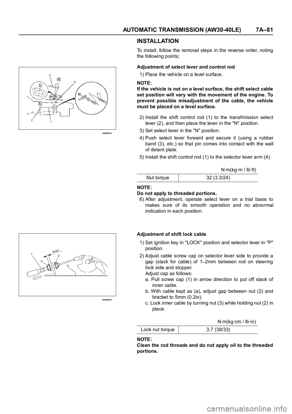
Adjustment of select lever and control rod
1) Place the vehicle on a level surface.
NOTE:
If the vehicle is not on a level surface, the shift select cable
set position will vary with the movement of the engine. To
prevent possible misadjustment of the cable, the vehicle
must be placed on a level surface.
2) Install the shift control rod (1) to the transfmission select
lever (2), and then place the lever in the "N" position.
3) Set select lever in the "N" position.
4) Push select lever forward and secure it (using a rubber
band (3), etc.) so that pin comes into contact with the wall
of detent plate.
5) Install the shift control rod (1) to the selector lever arm (4).
NOTE:
Do not apply to threaded portions.
6) After adjustment, operate select lever on a trial basis to
makes sure of its smooth operation and no abnormal
indication in each position.
Adjustment of shift lock cable
1) Set ignition key in "LOCK" position and selector lever in "P"
position.
2) Adjust cable screw cap on selector lever side to provide a
gap (slack for cable) of 1–2mm between rod on steering
lock side and stopper.
Adjust cap as follows:
a. Pull screw cap (1) in arrow direction to put off slack of
inner cable.
b. With cable kept as (a), adjust gap between nut (2) and
bracket to 5mm (0.2in).
c. Lock inner cable by tur ning nut (3) while holding nut (2) in
place.
NOTE:
Clean the rod threads and do not apply oil to the threaded
portions.Nꞏm(kgꞏm / lbꞏft)
Nut torque 32 (3.3/24)
Nꞏm(kgꞏcm / lbꞏin)
Lock nut torque 3.7 (38/33)
Page 5867 of 6000
7A–86 AUTOMATIC TRANSMISSION (AW30-40LE)
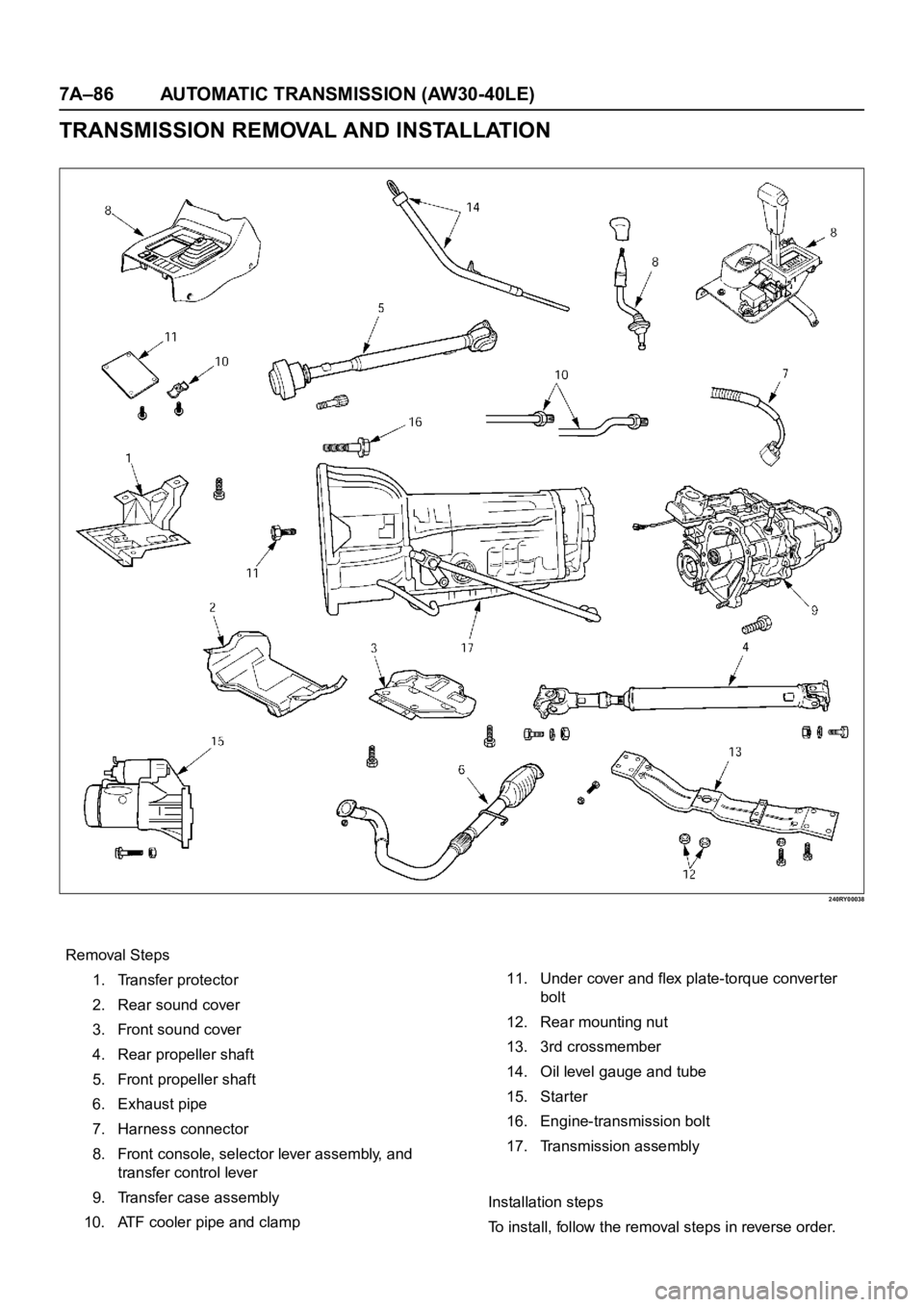
TRANSMISSION REMOVAL AND INSTALLATION
240RY00038
Removal Steps
1. Transfer protector
2. Rear sound cover
3. Front sound cover
4. Rear propeller shaft
5. Front propeller shaft
6. Exhaust pipe
7. Harness connector
8. Front console, selector lever assembly, and
transfer control lever
9. Transfer case assembly
10. ATF cooler pipe and clamp11. Under cover and flex plate-torque conver ter
bolt
12. Rear mounting nut
13. 3rd crossmember
14. Oil level gauge and tube
15. Starter
16. Engine-transmission bolt
17. Transmission assembly
Installation steps
To install, follow the removal steps in reverse order.
Page 5868 of 6000
AUTOMATIC TRANSMISSION (AW30-40LE) 7A–87
253RY00001
REMOVAL
Preparation
:
• Remove engine hood.
• Disconnect negative (–) battery cable.
1. Transfer protector
2. Rear sound cover
3. Front sound cover
4. Rear propeller shaft
5. Front propeller shaft
NOTE:
Apply alignment marks on the flange at both front and rear
sides.
6. Exhaust pipe
• Remove the 2nd front exhaust pipe from the 1st front
exhaust pipe and exhaust silencer.
7. Transmission harness connector
• Disconnect the harness connectors from the
transmission.
8. Front console, selector lever assembly, and transfer
control lever
• Disconnect the transfer control lever knob.
• Remove the front console.
• Disconnect the harness connector.
• Remove the selector lever assembly.
• Disconnect the shift control rod from the transmission.
9. Transfer case assembly
• Disconnect the breather hose from the transfer case.
• Remove the transfer case assembly from the
transmission.
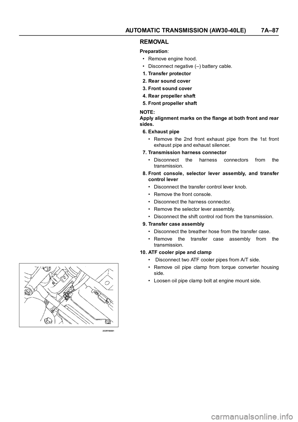
10. ATF cooler pipe and clamp
• Disconnect two ATF cooler pipes from A/T side.
• Remove oil pipe clamp from torque converter housing
side.
• Loosen oil pipe clamp bolt at engine mount side.