1998 OPEL FRONTERA engine
[x] Cancel search: enginePage 5815 of 6000
7A–34 AUTOMATIC TRANSMISSION (AW30-40LE)
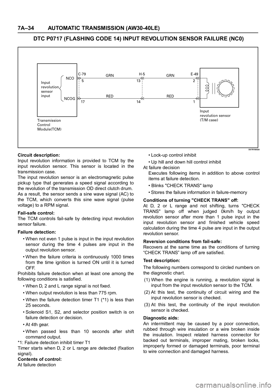
DTC P0717 (FLASHING CODE 14) INPUT REVOLUTION SENSOR FAILURE (NC0)
D07RY00020
Circuit description:
Input revolution information is provided to TCM by the
input revolution sensor. This sensor is located in the
transmission case.
The input revolution sensor is an electromagnetic pulse
pickup type that generates a speed signal according to
the revolution of the transmission OD direct clutch drum.
As a result, the sensor sends a sine wave signal (AC) to
the TCM, which conver ts this sine wave signal (pulse
voltage) to a RPM signal.
Fail-safe control:
The TCM controls fail-safe by detecting input revolution
sensor failure.
Failure detection:
• When not even 1 pulse is input in the input revolution
sensor during the time 4 pulses are input in the
output revolution sensor.
• When the failure criteria is continuously 1000 times
from the time ignition is turned ON until it is turned
OFF.
Prohibits failure detection when at least one among the
following conditions is satisfied.
• When D, 2 and L range signal is not fixed.
• When output revolution is less than 775 rpm.
• When the failure detection timer T1 (*1) is less than
25 seconds.
• Solenoid S1, S2, and selector position switch is on
failure detection or decision.
• At 4th gear.
• When passed less than 10 seconds after shift
command output.
*1: Failure detection inhibit timer T1
Timer star ts when D, 2 or L range are detected (fixation
signal).
Contents of control:
At failure detection• Lock-up control inhibit
• Up hill and down hill control inhibit
At failure decision
Executes following items in addition to above control
items at failure detection.
• Blinks "CHECK TRANS" lamp
• Stores the failure information in failure-memory
Conditions of turning "CHECK TRANS" off:
At D, 2 or L range and not shifting, turns "CHECK
TRANS" lamp off when judged 0km/h by output
revolution sensor after more than 1 pulse input in the
input revolution sensor and finished vehicle speed
calculation during the time 4 pulse are input in the output
revolution sensor.
Reversion conditions from fail-safe:
Recovers at the same time as the conditions of turning
“CHECK TRANS” lamp off are satisfied.
Test description:
The following numbers correspond to circled numbers on
the diagnostic char t.
(1) When the engine is running, a revolution signal is
input from the input revolution sensor to the TCM.
(2) At this test, the continuity of circuit wiring and the
input revolution sensor is checked.
(3) At this test, the continuity of the input revolution
sensor is checked.
Diagnostic aids:
An intermittent may be caused by a poor connection,
rubbed through wire insulation or a wire broken inside
the insulation. Inspect related harness connector for
backed out terminals, improper mating, broken locks,
improperly formed or damaged terminals, poor terminal
to wire connection and damaged harness.
Page 5819 of 6000
7A–38 AUTOMATIC TRANSMISSION (AW30-40LE)
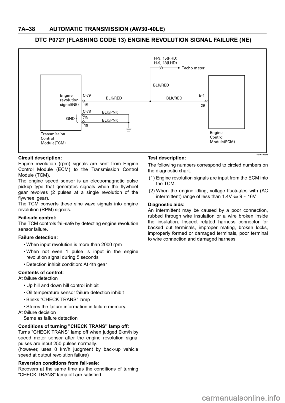
DTC P0727 (FLASHING CODE 13) ENGINE REVOLUTION SIGNAL FAILURE (NE)
D07RY00019Circuit description:
Engine revolution (rpm) signals are sent from Engine
Control Module (ECM) to the Transmission Control
Module (TCM).
The engine speed sensor is an electromagnetic pulse
pickup type that generates signals when the flywheel
gear revolves (2 pulses at a single revolution of the
flywheel gear).
The TCM converts these sine wave signals into engine
revolution (RPM) signals.
Fail-safe control:
The TCM controls fail-safe by detecting engine revolution
sensor failure.
Failure detection:
• When input revolution is more than 2000 rpm
• When not even 1 pulse is input in the engine
revolution signal during 5 seconds
• Detection inhibit condition: At 4th gear
Contents of control:
At failure detection
• Up hill and down hill control inhibit
• Oil temperature sensor failure detection inhibit
• Blinks "CHECK TRANS" lamp
• Stores the failure information in failure memory.
At failure decision
Same as failure detection
Conditions of turning "CHECK TRANS" lamp off:
Turns "CHECK TRANS" lamp off when judged 0km/h by
speed meter sensor after the engine revolution signal
pulses are input 250 pulses normally.
(however, uses 0 km/h judgment by back-up vehicle
speed at output revolution failure)
Reversion conditions from fail-safe:
Recovers at the same time as the conditions of turning
“CHECK TRANS” lamp off are satisfied.Test description:
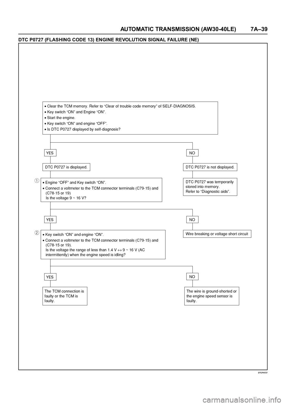
The following numbers correspond to circled numbers on
the diagnostic char t.
(1) Engine revolution signals are input from the ECM into
the TCM.
(2) When the engine idling, voltage fluctuates with (AC
intermittent) range of less than 1.4V
9 16V.
Diagnostic aids:
An intermittent may be caused by a poor connection,
rubbed through wire insulation or a wire broken inside
the insulation. Inspect related harness connector for
backed out terminals, improper mating, broken locks,
improperly formed or damaged terminals, poor terminal
to wire connection and damaged harness.
Page 5820 of 6000
AUTOMATIC TRANSMISSION (AW30-40LE) 7A–39
DTC P0727 (FLASHING CODE 13) ENGINE REVOLUTION SIGNAL FAILURE (NE)
DTCP0727
Page 5831 of 6000
7A–50 AUTOMATIC TRANSMISSION (AW30-40LE)
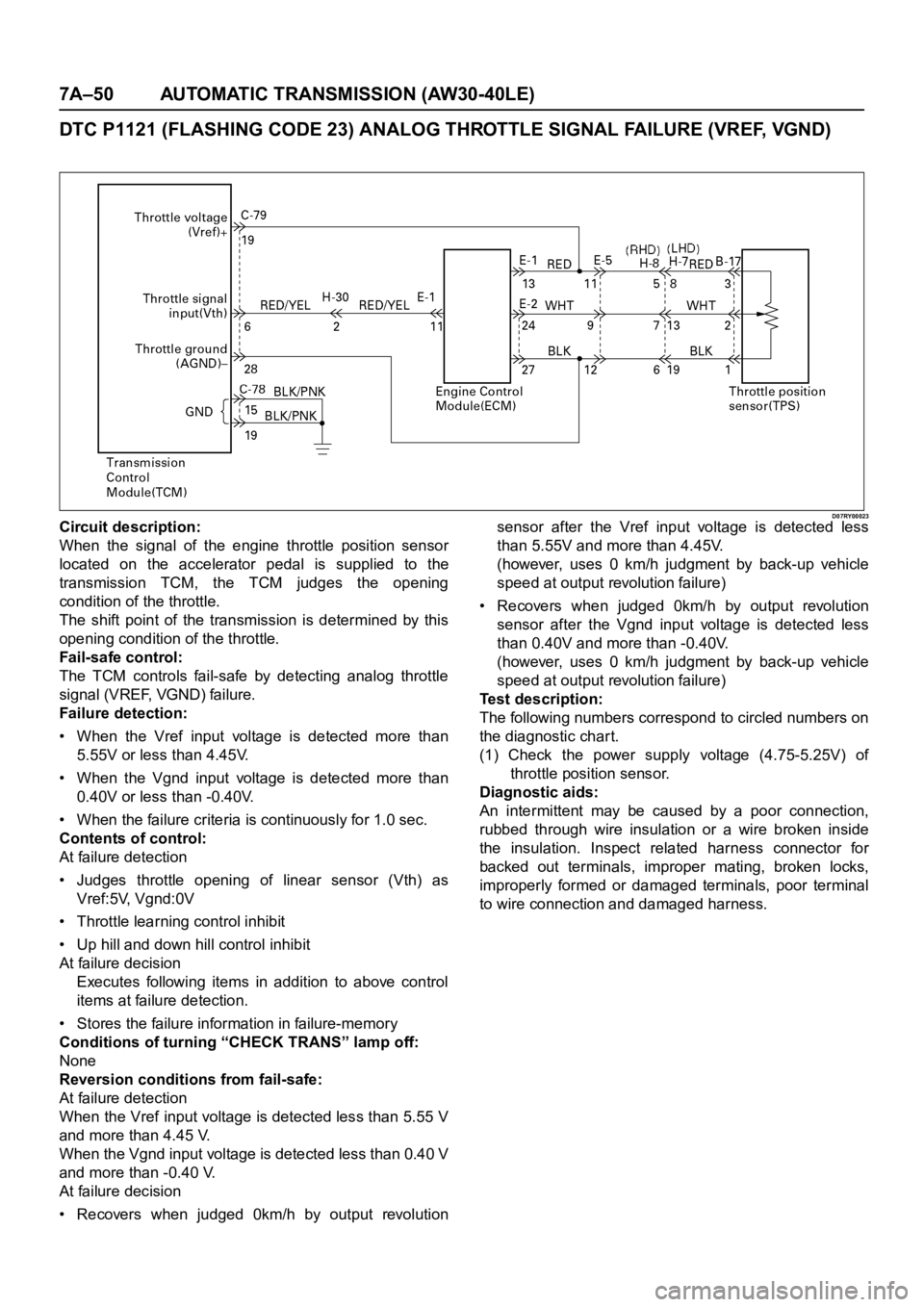
DTC P1121 (FLASHING CODE 23) ANALOG THROTTLE SIGNAL FAILURE (VREF, VGND)
D07RY00023Circuit description:
When the signal of the engine throttle position sensor
located on the accelerator pedal is supplied to the
transmission TCM, the TCM judges the opening
condition of the throttle.
The shift point of the transmission is determined by this
opening condition of the throttle.
Fail-safe control:
The TCM controls fail-safe by detecting analog throttle
signal (VREF, VGND) failure.
Failure detection:
• When the Vref input voltage is detected more than
5.55V or less than 4.45V.
• When the Vgnd input voltage is detected more than
0.40V or less than -0.40V.
• When the failure criteria is continuously for 1.0 sec.
Contents of control:
At failure detection
• Judges throttle opening of linear sensor (Vth) as
Vref:5V, Vgnd:0V
• Throttle learning control inhibit
• Up hill and down hill control inhibit
At failure decision
Executes following items in addition to above control
items at failure detection.
• Stores the failure information in failure-memory
Conditions of turning “CHECK TRANS” lamp off:
None
Reversion conditions from fail-safe:
At failure detection
When the Vref input voltage is detected less than 5.55 V
and more than 4.45 V.
When the Vgnd input voltage is detected less than 0.40 V
and more than -0.40 V.
At failure decision
• Recovers when judged 0km/h by output revolutionsensor after the Vref input voltage is detected less
than 5.55V and more than 4.45V.
(however, uses 0 km/h judgment by back-up vehicle
speed at output revolution failure)
• Recovers when judged 0km/h by output revolution
sensor after the Vgnd input voltage is detected less
than 0.40V and more than -0.40V.
(however, uses 0 km/h judgment by back-up vehicle
speed at output revolution failure)
Test description:
The following numbers correspond to circled numbers on
the diagnostic char t.
(1) Check the power supply voltage (4.75-5.25V) of
throttle position sensor.
Diagnostic aids:
An intermittent may be caused by a poor connection,
rubbed through wire insulation or a wire broken inside
the insulation. Inspect related harness connector for
backed out terminals, improper mating, broken locks,
improperly formed or damaged terminals, poor terminal
to wire connection and damaged harness.
Page 5843 of 6000
7A–62 AUTOMATIC TRANSMISSION (AW30-40LE)
826RY00018
F07RY00024
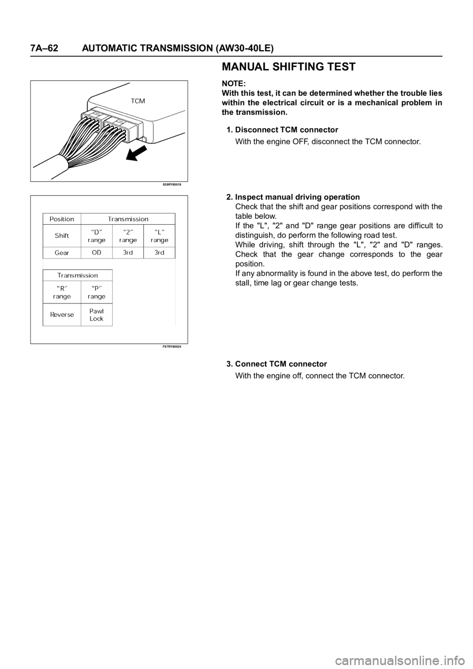
MANUAL SHIFTING TEST
NOTE:
With this test, it can be determined whether the trouble lies
within the electrical circuit or is a mechanical problem in
the transmission.
1. Disconnect TCM connector
With the engine OFF, disconnect the TCM connector.
2. Inspect manual driving operation
Check that the shift and gear positions correspond with the
table below.
If the "L", "2" and "D" range gear positions are difficult to
distinguish, do perform the following road test.
While driving, shift through the "L", "2" and "D" ranges.
Check that the gear change corresponds to the gear
position.
If any abnormality is found in the above test, do perform the
stall, time lag or gear change tests.
3. Connect TCM connector
With the engine off, connect the TCM connector.
Page 5844 of 6000
AUTOMATIC TRANSMISSION (AW30-40LE) 7A–63
F07RY00002
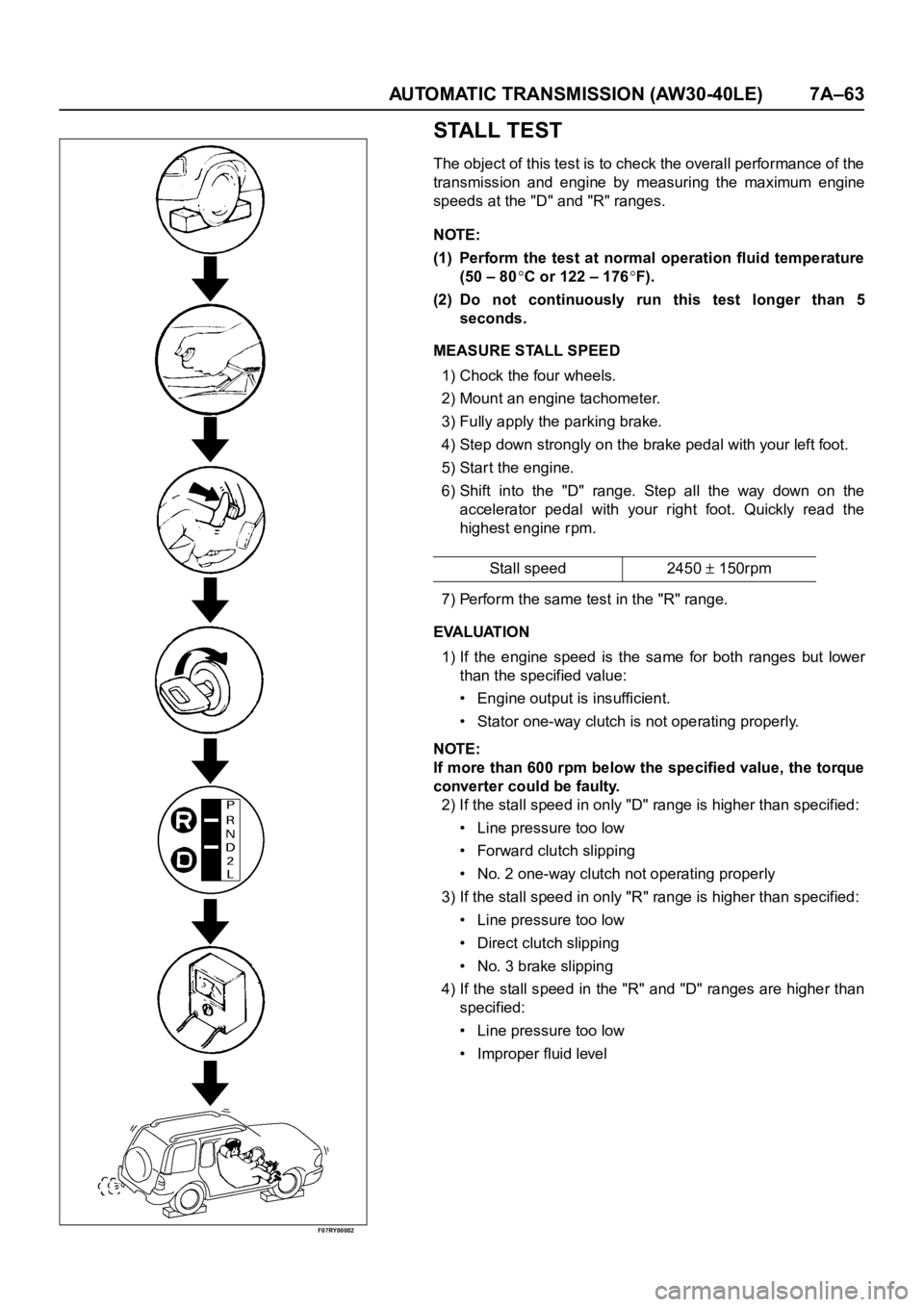
STALL TEST
The object of this test is to check the overall performance of the
transmission and engine by measuring the maximum engine
speeds at the "D" and "R" ranges.
NOTE:
(1) Perform the test at normal operation fluid temperature
(50 – 80
C or 122 – 176F).
(2) Do not continuously run this test longer than 5
seconds.
MEASURE STALL SPEED
1) Chock the four wheels.
2) Mount an engine tachometer.
3) Fully apply the parking brake.
4) Step down strongly on the brake pedal with your left foot.
5) Star t the engine.
6) Shift into the "D" range. Step all the way down on the
accelerator pedal with your right foot. Quickly read the
highest engine rpm.
7) Perform the same test in the "R" range.
EVALUATION
1) If the engine speed is the same for both ranges but lower
than the specified value:
• Engine output is insufficient.
• Stator one-way clutch is not operating properly.
NOTE:
If more than 600 rpm below the specified value, the torque
converter could be faulty.
2) If the stall speed in only "D" range is higher than specified:
• Line pressure too low
• Forward clutch slipping
• No. 2 one-way clutch not operating properly
3) If the stall speed in only "R" range is higher than specified:
• Line pressure too low
• Direct clutch slipping
• No. 3 brake slipping
4) If the stall speed in the "R" and "D" ranges are higher than
specified:
• Line pressure too low
• Improper fluid levelStall speed 2450
150rpm
Page 5845 of 6000
7A–64 AUTOMATIC TRANSMISSION (AW30-40LE)
F07RY00003
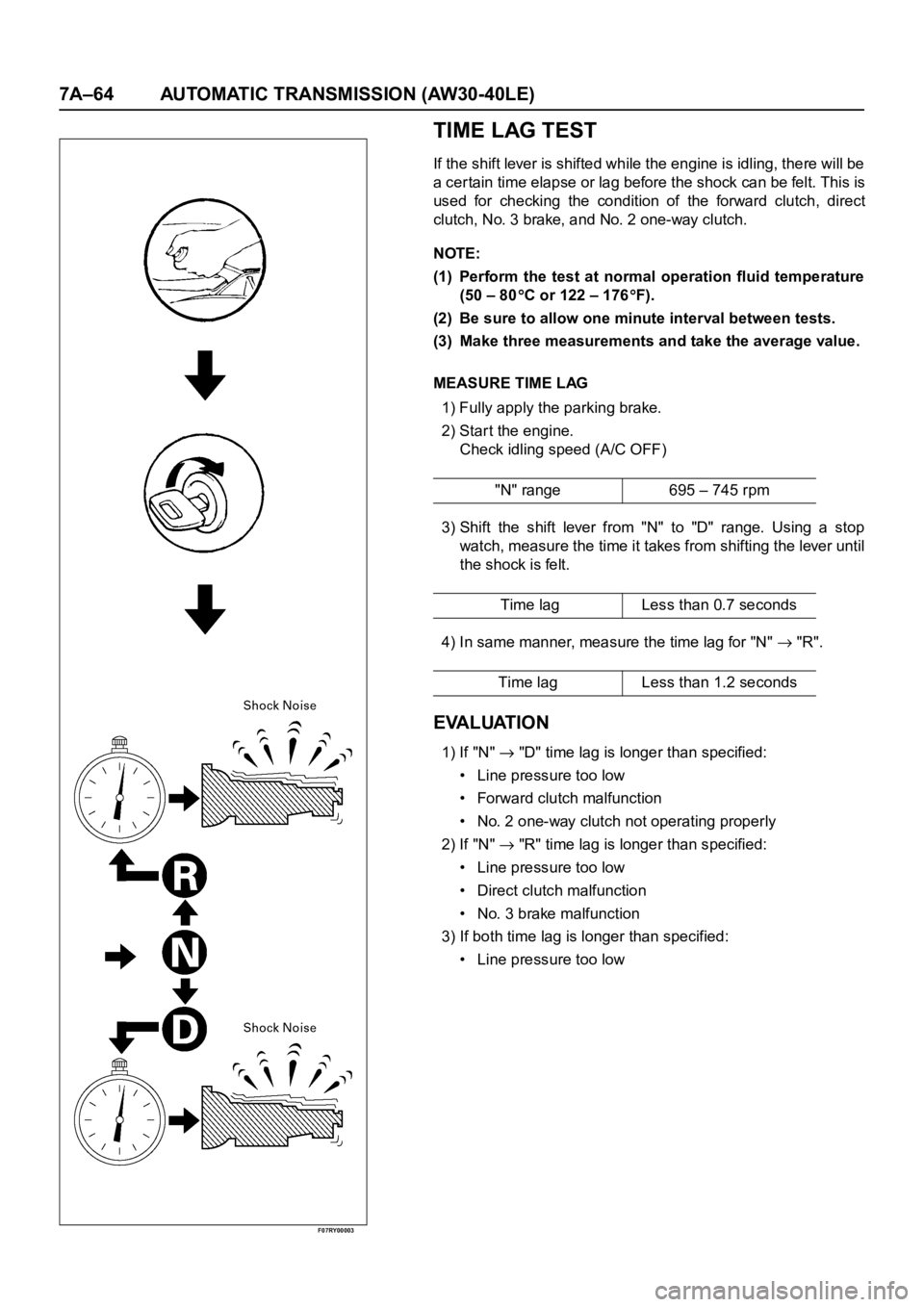
TIME LAG TEST
If the shift lever is shifted while the engine is idling, there will be
a cer tain time elapse or lag before the shock can be felt. This is
used for checking the condition of the forward clutch, direct
clutch, No. 3 brake, and No. 2 one-way clutch.
NOTE:
(1) Perform the test at normal operation fluid temperature
(50 – 80
C or 122 – 176F).
(2) Be sure to allow one minute interval between tests.
(3) Make three measurements and take the average value.
MEASURE TIME LAG
1) Fully apply the parking brake.
2) Start the engine.
Check idling speed (A/C OFF)
3) Shift the shift lever from "N" to "D" range. Using a stop
watch, measure the time it takes from shifting the lever until
the shock is felt.
4) In same manner, measure the time lag for "N"
"R".
EVALUATION
1) If "N" "D" time lag is longer than specified:
• Line pressure too low
• Forward clutch malfunction
• No. 2 one-way clutch not operating properly
2) If "N"
"R" time lag is longer than specified:
• Line pressure too low
• Direct clutch malfunction
• No. 3 brake malfunction
3) If both time lag is longer than specified:
• Line pressure too low"N" range 695 – 745 rpm
Time lag Less than 0.7 seconds
Time lag Less than 1.2 seconds
Page 5846 of 6000
AUTOMATIC TRANSMISSION (AW30-40LE) 7A–65
F07RY00004
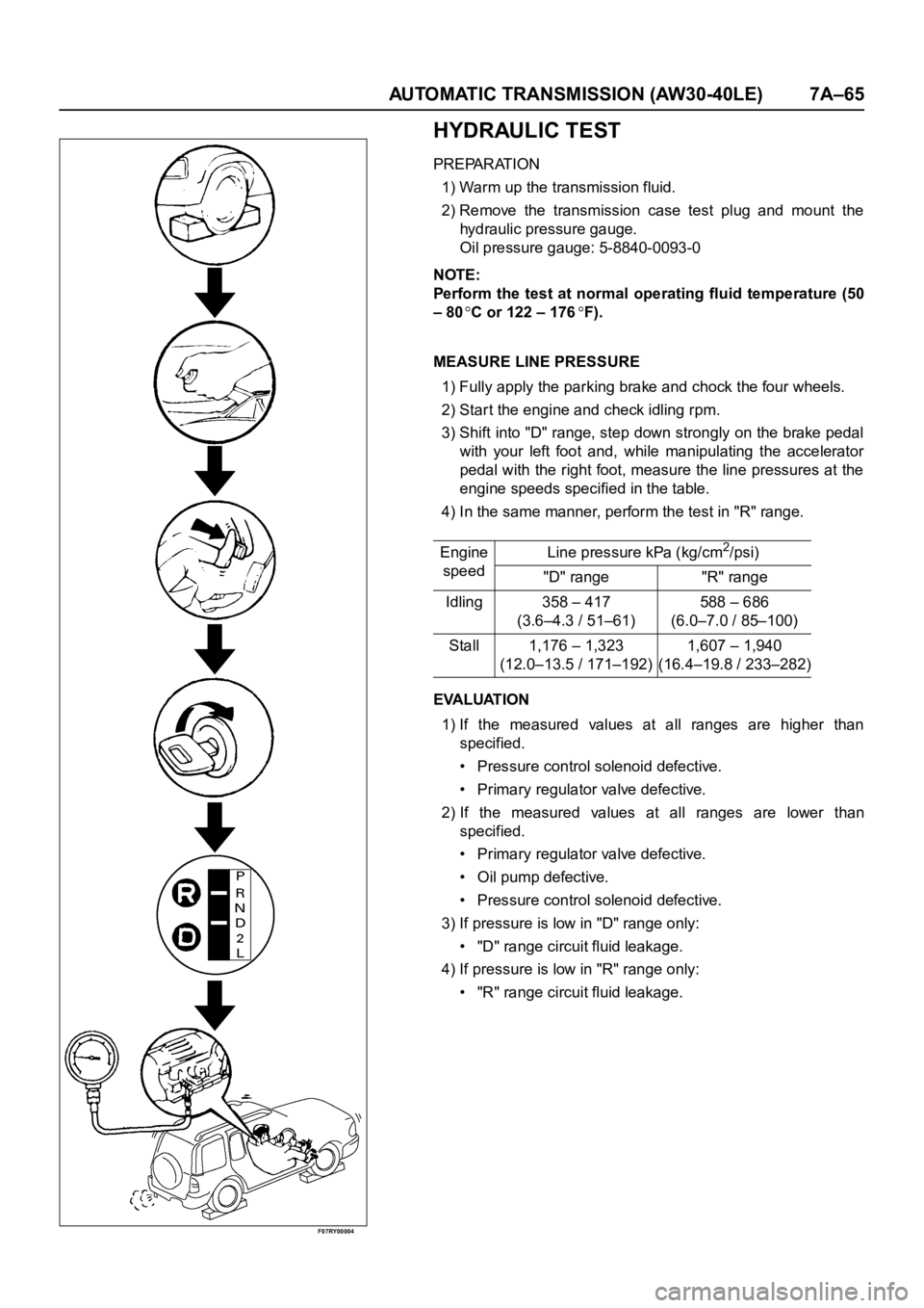
HYDRAULIC TEST
PREPARATION
1) Warm up the transmission fluid.
2) Remove the transmission case test plug and mount the
hydraulic pressure gauge.
Oil pressure gauge: 5-8840-0093-0
NOTE:
Perform the test at normal operating fluid temperature (50
– 80
C or 122 – 176F).
MEASURE LINE PRESSURE
1) Fully apply the parking brake and chock the four wheels.
2) Start the engine and check idling rpm.
3) Shift into "D" range, step down strongly on the brake pedal
with your left foot and, while manipulating the accelerator
pedal with the right foot, measure the line pressures at the
engine speeds specified in the table.
4) In the same manner, perform the test in "R" range.
EVALUATION
1) If the measured values at all ranges are higher than
specified.
• Pressure control solenoid defective.
• Primary regulator valve defective.
2) If the measured values at all ranges are lower than
specified.
• Primary regulator valve defective.
• Oil pump defective.
• Pressure control solenoid defective.
3) If pressure is low in "D" range only:
• "D" range circuit fluid leakage.
4) If pressure is low in "R" range only:
• "R" range circuit fluid leakage. Engine
speedLine pressure kPa (kg/cm
2/psi)
"D" range "R" range
Idling 358 – 417
(3.6–4.3 / 51–61)588 – 686
(6.0–7.0 / 85–100)
Stall 1,176 – 1,323
(12.0–13.5 / 171–192)1,607 – 1,940
(16.4–19.8 / 233–282)