Page 1939 of 6000
6E–46
4JX1–TC ENGINE DRIVEABILITY AND EMISSIONS
No Malfunction Indicator Lamp (MIL)
StepNo Ye s Va l u e ( s ) Action
15Locate and repair the short to ground in the ECM
ignition feed circuit or ECM battery feed circuit.
Is the action complete?
—Verify repair—
16Locate and repair the short to ground in the ignition
feed circuit to the instrument cluster, and replace the
fuse.
Is the action complete?
—Verify repair—
17Replace the ECM (Refer to the Data Programming in
Case of ECM change).
Is the action complete?
—Verify repair—
18Check the MIL driver circuit for a poor connection at the
instrument panel connector.
Was a problem found?
—Verify repair
Go to
Instrument
Panel
in
Electrical
Diagnosis
Page 1940 of 6000

6E–47 4JX1–TC ENGINE DRIVEABILITY AND EMISSIONS
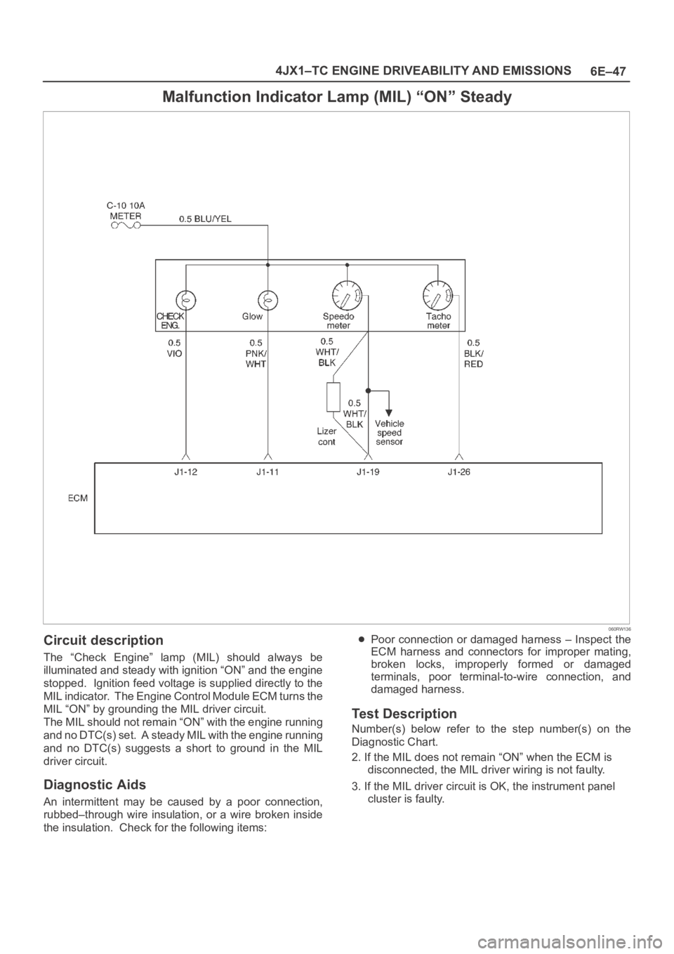
Malfunction Indicator Lamp (MIL) “ON” Steady
060RW136
Circuit description
The “Check Engine” lamp (MIL) should always be
illuminated and steady with ignition “ON” and the engine
stopped. Ignition feed voltage is supplied directly to the
MIL indicator. The Engine Control Module ECM turns the
MIL “ON” by grounding the MIL driver circuit.
The MIL should not remain “ON” with the engine running
and no DTC(s) set. A steady MIL with the engine running
and no DTC(s) suggests a short to ground in the MIL
driver circuit.
Diagnostic Aids
An intermittent may be caused by a poor connection,
rubbed–through wire insulation, or a wire broken inside
the insulation. Check for the following items:
Poor connection or damaged harness – Inspect the
ECM harness and connectors for improper mating,
broken locks, improperly formed or damaged
terminals, poor terminal-to-wire connection, and
damaged harness.
Test Description
Number(s) below refer to the step number(s) on the
Diagnostic Chart.
2. If the MIL does not remain “ON” when the ECM is
disconnected, the MIL driver wiring is not faulty.
3. If the MIL driver circuit is OK, the instrument panel
cluster is faulty.
Page 1941 of 6000

6E–48
4JX1–TC ENGINE DRIVEABILITY AND EMISSIONS
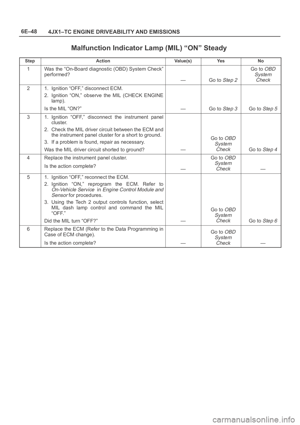
Malfunction Indicator Lamp (MIL) “ON” Steady
StepActionVa l u e ( s )Ye sNo
1Was the “On-Board diagnostic (OBD) System Check”
performed?
—Go to Step 2
Go to OBD
System
Check
21. Ignition “OFF,” disconnect ECM.
2. Ignition “ON,” observe the MIL (CHECK ENGINE
lamp).
Is the MIL “ON?”
—Go to Step 3Go to Step 5
31. Ignition “OFF,” disconnect the instrument panel
cluster.
2. Check the MIL driver circuit between the ECM and
the instrument panel cluster for a short to ground.
3. If a problem is found, repair as necessary.
Was the MIL driver circuit shorted to ground?
—
Go to OBD
System
Check
Go to Step 4
4Replace the instrument panel cluster.
Is the action complete?
—
Go to OBD
System
Check
—
51. Ignition “OFF,” reconnect the ECM.
2. Ignition “ON,” reprogram the ECM. Refer to
On-Vehicle Service in Engine Control Module and
Sensor
for procedures.
3. Using the Tech 2 output controls function, select
MIL dash lamp control and command the MIL
“OFF.”
Did the MIL turn “OFF?”
—
Go to OBD
System
Check
Go to Step 6
6Replace the ECM (Refer to the Data Programming in
Case of ECM change).
Is the action complete?
—
Go to OBD
System
Check
—
Page 2553 of 6000
8A–14LIGHTING SYSTEM
Map Light Switch/Bulb
Removal
1. Disconnect the battery ground cable.
2. Pull the map light body downward to release the lock.
3. Disconnect the connectors of the map light and the
sun roof switch.
4. Remove the map light switch.
5. Turn the socket counterclockwise to remove it.
6. Pull out the bulb from the socket.
805RS008
Installation
To install, follow the removal steps in the reverse order.
Cigarette Lighter Illumination Bulb
Removal
1. Disconnect the battery ground cable.
2. Remove eight screws to remove the instrument
cluster panel(2).
3. Turn the socket counterclockwise to remove it then
pull out the bulb(1).
826RS013
Installation
To install, follow the removal steps in the reverse order.
Page 2554 of 6000
LIGHTING SYSTEM8A–15
Ashtray Illumination Bulb
Removal
1. Disconnect the battery ground cable.
2. Removal eight screws to remove the instrument
cluster panel(1).
3. Remove the ashtray(5).
4. Remove four screws to remove the audio box(4).
5. Remove two screws to remove the ashtray guide(2).
6. Turn the socket counterclockwise to remove it then
pull out the bulb(3).
742RS001
Installation
To install, follow the removal steps in the reverse order.
Glove Box Illumination Bulb
Removal
1. Disconnect the battery ground cable.
2. Open the glove box lid, and then pull out the bulb(1).
805RS004
Installation
To install, follow the removal steps in the reverse order.
Page 2556 of 6000
LIGHTING SYSTEM8A–17
Starter Switch
Removal
1. Disconnect the battery ground cable.
2. Remove the front console assembly(1).
Refer to Instrument Panel Assembly in Body
Structure section.
3. Remove the lower cluster assembly(2).
Refer to the Instrument Panel Assembly in Body
Structure section.
4. Remove the instrument panel driver lower cover
assembly(3).
Refer to the Instrument Panel Assembly in Body
Structure section.
821RW024
5. Remove seven screws to remove the steering
cowl(6).
6. Disconnect the connector, remove the screw(4) and
then remove the starter switch(5).
431RW005
Installation
To install, follow the removal steps in the reverse order
noting the following point.
1. When installing the steering cowl(10), be sure to pass
the harnesses through the route as shown in the
figure so that the starter switch harness(7), the
combination switch harness(8) and the inflator
module harness(9) will not get caught.
431RW008
Page 2558 of 6000
LIGHTING SYSTEM8A–19
Fog Light Switch
Removal
1. Disconnect the battery ground cable.
2. Remove the front console assembly(1).
Refer to the Instrument Panel Assembly in Body
Structure section.
3. Remove the lower cluster assembly(2).
Refer to the Instrument Panel Assembly in Body
Structure section.
4. Remove the instrument panel driver lower cover
assembly(3).
Refer to the Instrument Panel Assembly in Body
Structure section.
821RW024
5. Remove the instrument panel cluster assembly(4).
Refer to the Instrument Panel Assembly in Body
Structure section.
6. Disconnect the connector and push the lock from the
back side of the instrument panel cluster assembly to
remove the fog light switch(5).
825RW027
Installation
To install, follow the removal steps in the reverse order,
noting the following point:
1. Push in the switch with your fingers until the switch is
locked securely.
Page 2561 of 6000
8A–22LIGHTING SYSTEM
Hazard Warning Switch
Removal
1. Disconnect the battery ground cable.
2. Remove the front console assembly(1).
Refer to the Instrument Panel Assembly in Body
Structure section.
3. Remove the lower cluster assembly(2).
Refer to the Instrument Panel Assembly in Body
Structure section.
4. Remove the instrument panel driver lower cover
assembly(3).
Refer to the Instrument Panel Assembly in Body
Structure section.
821RW024
5. Remove the instrument panel cluster assembly(4).
Refer to the Instrument Panel Assembly in Body
Structure section.
6. Disconnect the connector and push the lock from the
back side of the instrument panel cluster assembly to
remove the hazard warning switch(5).
825RW024
Installation
To install, follow the removal steps in the reverse order,
noting the following point.
1. Push in the switch with your fingers until it locks
securely.