1998 OPEL FRONTERA instrument cluster
[x] Cancel search: instrument clusterPage 3496 of 6000
9J1–9
RESTRAINT CONTROL SYSTEM
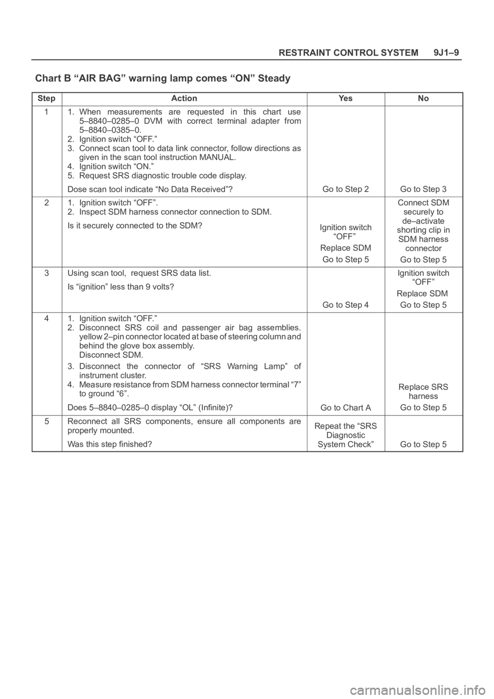
Chart B “AIR BAG” warning lamp comes “ON” Steady
StepActionYe sNo
11. When measurements are requested in this chart use
5–8840–0285–0 DVM with correct terminal adapter from
5–8840–0385–0.
2. Ignition switch “OFF.”
3. Connect scan tool to data link connector, follow directions as
given in the scan tool instruction MANUAL.
4. Ignition switch “ON.”
5. Request SRS diagnostic trouble code display.
Dose scan tool indicate “No Data Received”?
Go to Step 2Go to Step 3
21. Ignition switch “OFF”.
2. Inspect SDM harness connector connection to SDM.
Is it securely connected to the SDM?
Ignition switch
“OFF”
Replace SDM
Go to Step 5
Connect SDM
securely to
de–activate
shorting clip in
SDM harness
connector
Go to Step 5
3Using scan tool, request SRS data list.
Is “ignition” less than 9 volts?
Go to Step 4
Ignition switch
“OFF”
Replace SDM
Go to Step 5
41. Ignition switch “OFF.”
2. Disconnect SRS coil and passenger air bag assemblies.
yellow 2–pin connector located at base of steering column and
behind the glove box assembly.
Disconnect SDM.
3. Disconnect the connector of “SRS Warning Lamp” of
instrument cluster.
4. Measure resistance from SDM harness connector terminal “7”
to ground “6”.
Does 5–8840–0285–0 display “OL” (Infinite)?
Go to Chart A
Replace SRS
harness
Go to Step 5
5Reconnect all SRS components, ensure all components are
properly mounted.
Was this step finished?Repeat the “SRS
Diagnostic
System Check”
Go to Step 5
Page 3497 of 6000
RESTRAINT CONTROL SYSTEM 9J1–10
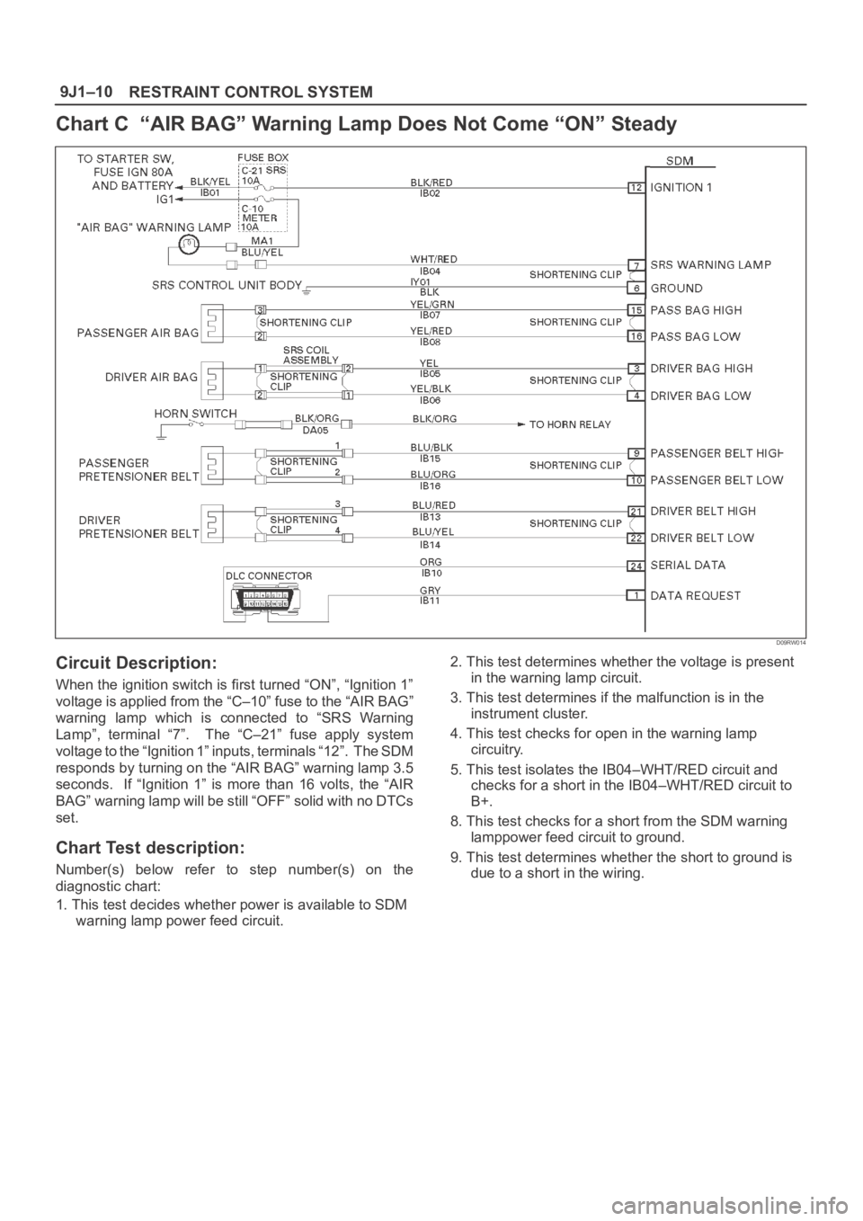
Chart C “AIR BAG” Warning Lamp Does Not Come “ON” Steady
D09RW014
Circuit Description:
When the ignition switch is first turned “ON”, “Ignition 1”
voltage is applied from the “C–10” fuse to the “AIR BAG”
warning lamp which is connected to “SRS Warning
Lamp”, terminal “7”. The “C–21” fuse apply system
voltage to the “Ignition 1” inputs, terminals “12”. The SDM
responds by turning on the “AIR BAG” warning lamp 3.5
seconds. If “Ignition 1” is more than 16 volts, the “AIR
BAG” warning lamp will be still “OFF” solid with no DTCs
set.
Chart Test description:
Number(s) below refer to step number(s) on the
diagnostic chart:
1. This test decides whether power is available to SDM
warning lamp power feed circuit.2. This test determines whether the voltage is present
in the warning lamp circuit.
3. This test determines if the malfunction is in the
instrument cluster.
4. This test checks for open in the warning lamp
circuitry.
5. This test isolates the IB04–WHT/RED circuit and
checks for a short in the IB04–WHT/RED circuit to
B+.
8. This test checks for a short from the SDM warning
lamppower feed circuit to ground.
9. This test determines whether the short to ground is
due to a short in the wiring.
Page 3498 of 6000
9J1–11
RESTRAINT CONTROL SYSTEM
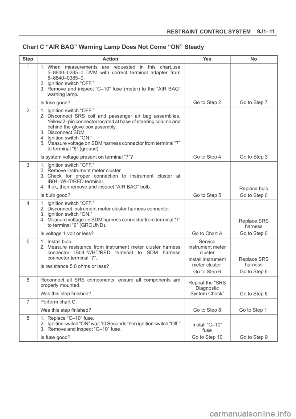
Chart C “AIR BAG” Warning Lamp Does Not Come “ON” Steady
StepActionYe sNo
11. When measurements are requested in this chart,use
5–8840–0285–0 DVM with correct terminal adapter from
5–8840–0385–0.
2. Ignition switch “OFF.”
3. Remove and inspect “C–10” fuse (meter) to the “AIR BAG”
warning lamp.
Is fuse good?
Go to Step 2Go to Step 7
21. Ignition switch “OFF.”
2. Disconnect SRS coil and passenger air bag assemblies.
Yellow 2–pin connector located at base of steering column and
behind the glove box assembly.
3. Disconnect SDM.
4. Ignition switch “ON.”
5. Measure voltage on SDM harness connector from terminal “7”
to terminal “6” (ground).
Is system voltage present on terminal “7”?
Go to Step 4Go to Step 3
31. Ignition switch “OFF.”
2. Remove instrument meter cluster.
3. Check for proper connection to instrument cluster at
IB04–WHT/RED terminal.
4. If ok, then remove and inspect “AIR BAG” bulb.
Is bulb good?
Go to Step 5
Replace bulb
Go to Step 6
41. Ignition switch “OFF.”
2. Disconnect instrument meter cluster harness connector.
3. Ignition switch “ON.”
4. Measure voltage on SDM harness connector from terminal “7”
to terminal “6” (GROUND).
Is voltage 1 volt or less?
Go to Chart A
Replace SRS
harness
Go to Step 6
51. Install bulb.
2. Measure resistance from instrument meter cluster harness
connector IB04–WHT/RED terminal to SDM harness
connector terminal “7”.
Is resistance 5.0 ohms or less?Service
instrument meter
cluster
Install instrument
meter cluster
Go to Step 6
Replace SRS
harness
Go to Step 6
6Reconnect all SRS components, ensure all components are
properly mounted.
Was this step finished?Repeat the “SRS
Diagnostic
System Check”
Go to Step 6
7Perform chart C.
Was this step finished?
Go to Step 8Go to Step 1
81. Replace “C–10” fuse.
2. Ignition switch “ON” wait 10 Seconds then ignition switch “Off.”
3. Remove and inspect “C–10” fuse.
Is fuse good?
Install “C–10”
fuse
Go to Step 10
Go to Step 9
Page 3555 of 6000
10A–4
CRUISE CONTROL SYSTEM
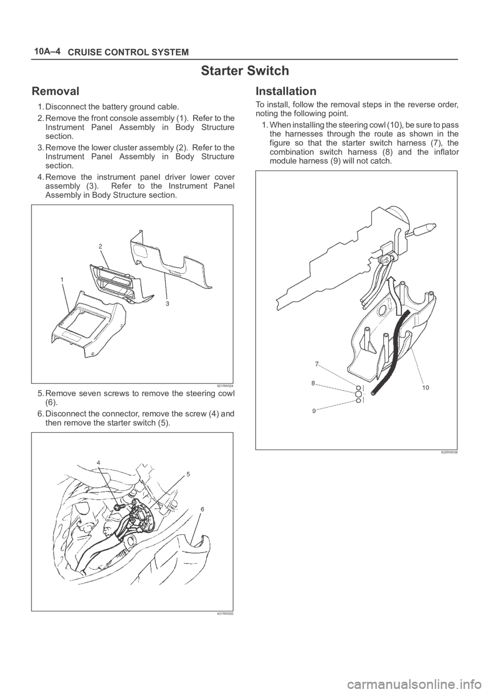
Starter Switch
Removal
1. Disconnect the battery ground cable.
2. Remove the front console assembly (1). Refer to the
Instrument Panel Assembly in Body Structure
section.
3. Remove the lower cluster assembly (2). Refer to the
Instrument Panel Assembly in Body Structure
section.
4. Remove the instrument panel driver lower cover
assembly (3). Refer to the Instrument Panel
Assembly in Body Structure section.
821RW024
5. Remove seven screws to remove the steering cowl
(6).
6. Disconnect the connector, remove the screw (4) and
then remove the starter switch (5).
431RW005
Installation
To install, follow the removal steps in the reverse order,
noting the following point.
1. When installing the steering cowl (10), be sure to pass
the harnesses through the route as shown in the
figure so that the starter switch harness (7), the
combination switch harness (8) and the inflator
module harness (9) will not catch.
825RW058
Page 3556 of 6000
10A–5
CRUISE CONTROL SYSTEM
Cruise Control Main Switch
Removal
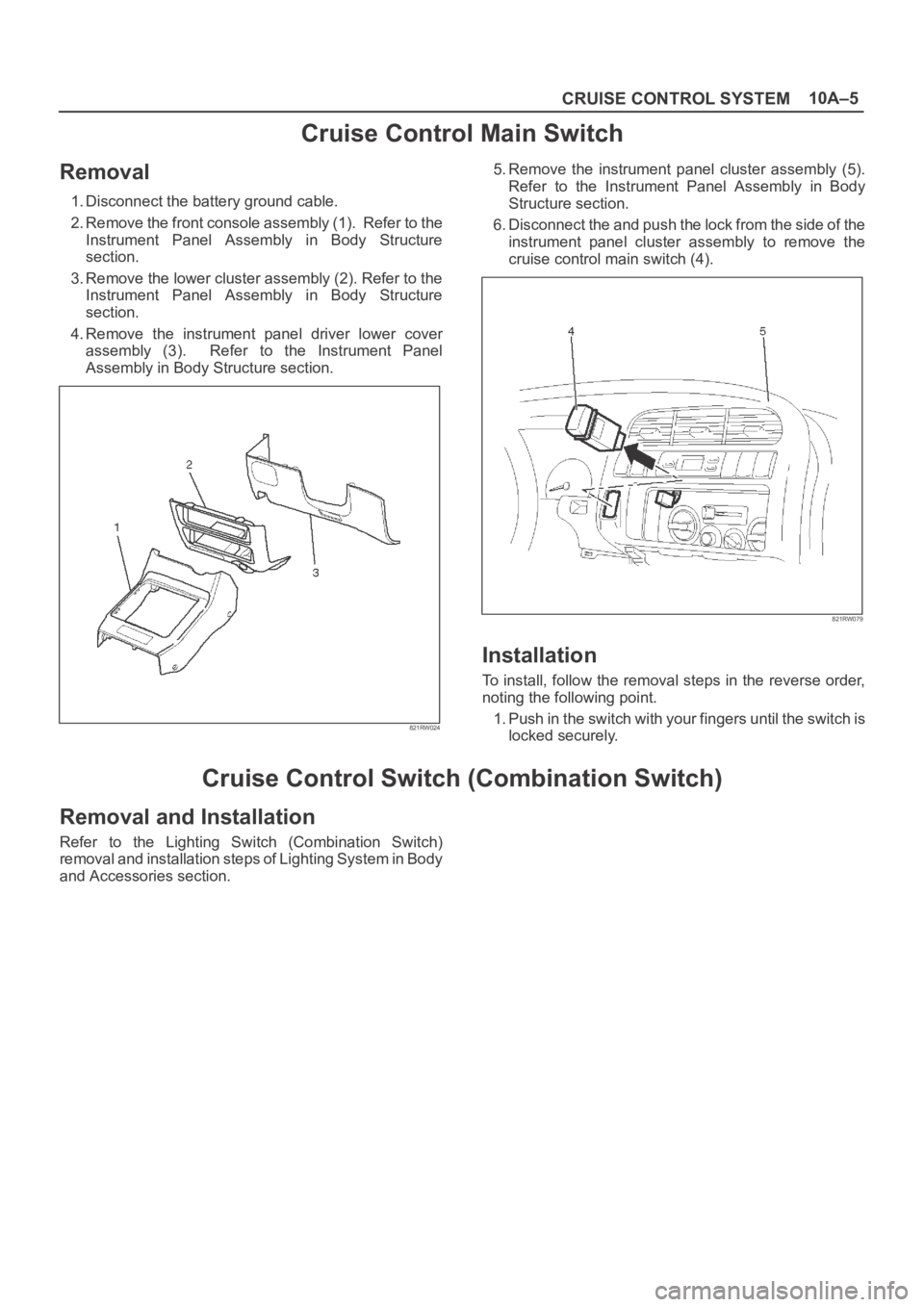
1. Disconnect the battery ground cable.
2. Remove the front console assembly (1). Refer to the
Instrument Panel Assembly in Body Structure
section.
3. Remove the lower cluster assembly (2). Refer to the
Instrument Panel Assembly in Body Structure
section.
4. Remove the instrument panel driver lower cover
assembly (3). Refer to the Instrument Panel
Assembly in Body Structure section.
821RW024
5. Remove the instrument panel cluster assembly (5).
Refer to the Instrument Panel Assembly in Body
Structure section.
6. Disconnect the and push the lock from the side of the
instrument panel cluster assembly to remove the
cruise control main switch (4).
821RW079
Installation
To install, follow the removal steps in the reverse order,
noting the following point.
1. Push in the switch with your fingers until the switch is
locked securely.
Cruise Control Switch (Combination Switch)
Removal and Installation
Refer to the Lighting Switch (Combination Switch)
removal and installation steps of Lighting System in Body
and Accessories section.
Page 4731 of 6000
6E–74
ENGINE DRIVEABILITY AND EMISSIONS
No Malfunction Indicator Lamp (MIL)
D06RW00006
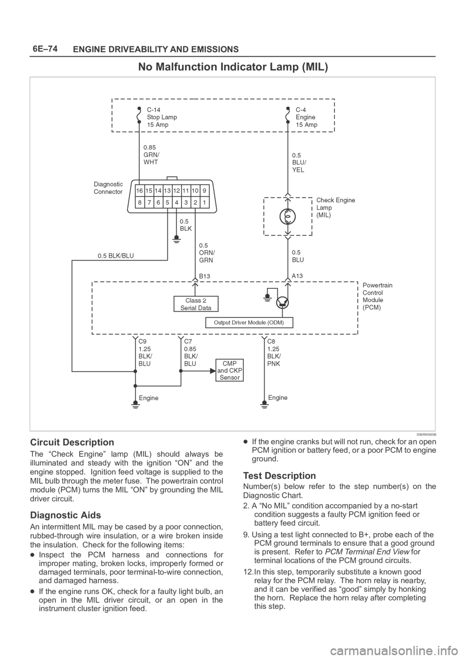
Circuit Description
The “Check Engine” lamp (MIL) should always be
illuminated and steady with the ignition “ON” and the
engine stopped. Ignition feed voltage is supplied to the
MIL bulb through the meter fuse. The powertrain control
module (PCM) turns the MIL “ON” by grounding the MIL
driver circuit.
Diagnostic Aids
An intermittent MIL may be cased by a poor connection,
rubbed-through wire insulation, or a wire broken inside
the insulation. Check for the following items:
Inspect the PCM harness and connections for
improper mating, broken locks, improperly formed or
damaged terminals, poor terminal-to-wire connection,
and damaged harness.
If the engine runs OK, check for a faulty light bulb, an
open in the MIL driver circuit, or an open in the
instrument cluster ignition feed.
If the engine cranks but will not run, check for an open
PCM ignition or battery feed, or a poor PCM to engine
ground.
Test Description
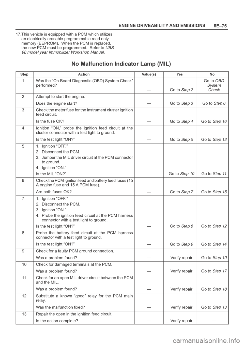
Number(s) below refer to the step number(s) on the
Diagnostic Chart.
2. A “No MIL” condition accompanied by a no-start
condition suggests a faulty PCM ignition feed or
battery feed circuit.
9. Using a test light connected to B+, probe each of the
PCM ground terminals to ensure that a good ground
is present. Refer to
PCM Terminal End View for
terminal locations of the PCM ground circuits.
12.In this step, temporarily substitute a known good
relay for the PCM relay. The horn relay is nearby,
and it can be verified as “good” simply by honking
the horn. Replace the horn relay after completing
this step.
Page 4732 of 6000
6E–75 ENGINE DRIVEABILITY AND EMISSIONS
17.This vehicle is equipped with a PCM which utilizes
an electrically erasable programmable read only
memory (EEPROM). When the PCM is replaced,
the new PCM must be programmed. Refer to
UBS
98 model year Immobilizer Workshop Manual.
No Malfunction Indicator Lamp (MIL)
StepActionVa l u e ( s )Ye sNo
1Was the “On-Board Diagnostic (OBD) System Check”
performed?
—Go to Step 2
Go to OBD
System
Check
2Attempt to start the engine.
Does the engine start?
—Go to Step 3Go to Step 6
3Check the meter fuse for the instrument cluster ignition
feed circuit.
Is the fuse OK?
—Go to Step 4Go to Step 16
4Ignition “ON,” probe the ignition feed circuit at the
cluster connector with a test light to ground.
Is the test light “ON?”
—Go to Step 5Go to Step 13
51. Ignition “OFF.”
2. Disconnect the PCM.
3. Jumper the MIL driver circuit at the PCM connector
to ground.
4. Ignition “ON.”
Is the MIL “ON?”
—Go to Step 10Go to Step 11
6Check the PCM ignition feed and battery feed fuses (15
A engine fuse and 15 A PCM fuse).
Are both fuses OK?
—Go to Step 7Go to Step 15
71. Ignition “OFF.”
2. Disconnect the PCM.
3. Ignition “ON.”
4. Probe the ignition feed circuit at the PCM harness
connector with a test light to ground.
Is the test light “ON?”
—Go to Step 8Go to Step 12
8Probe the battery feed circuit at the PCM harness
connector with a test light to ground.
Is the test light “ON?”
—Go to Step 9Go to Step 14
9Check for a faulty PCM ground connection.
Was a problem found?
—Verify repairGo to Step 10
10Check for damaged terminals at the PCM.
Was a problem found?
—Verify repairGo to Step 17
11Check for an open MIL driver circuit between the PCM
and the MIL.
Was a problem found?
—Verify repairGo to Step 18
12Substitute a known “good” relay for the PCM main
relay.
Was the malfunction fixed?
—Verify repairGo to Step 13
13Repair the open in the ignition feed circuit.
Is the action complete?
—Verify repair—
Page 4733 of 6000
6E–76
ENGINE DRIVEABILITY AND EMISSIONS
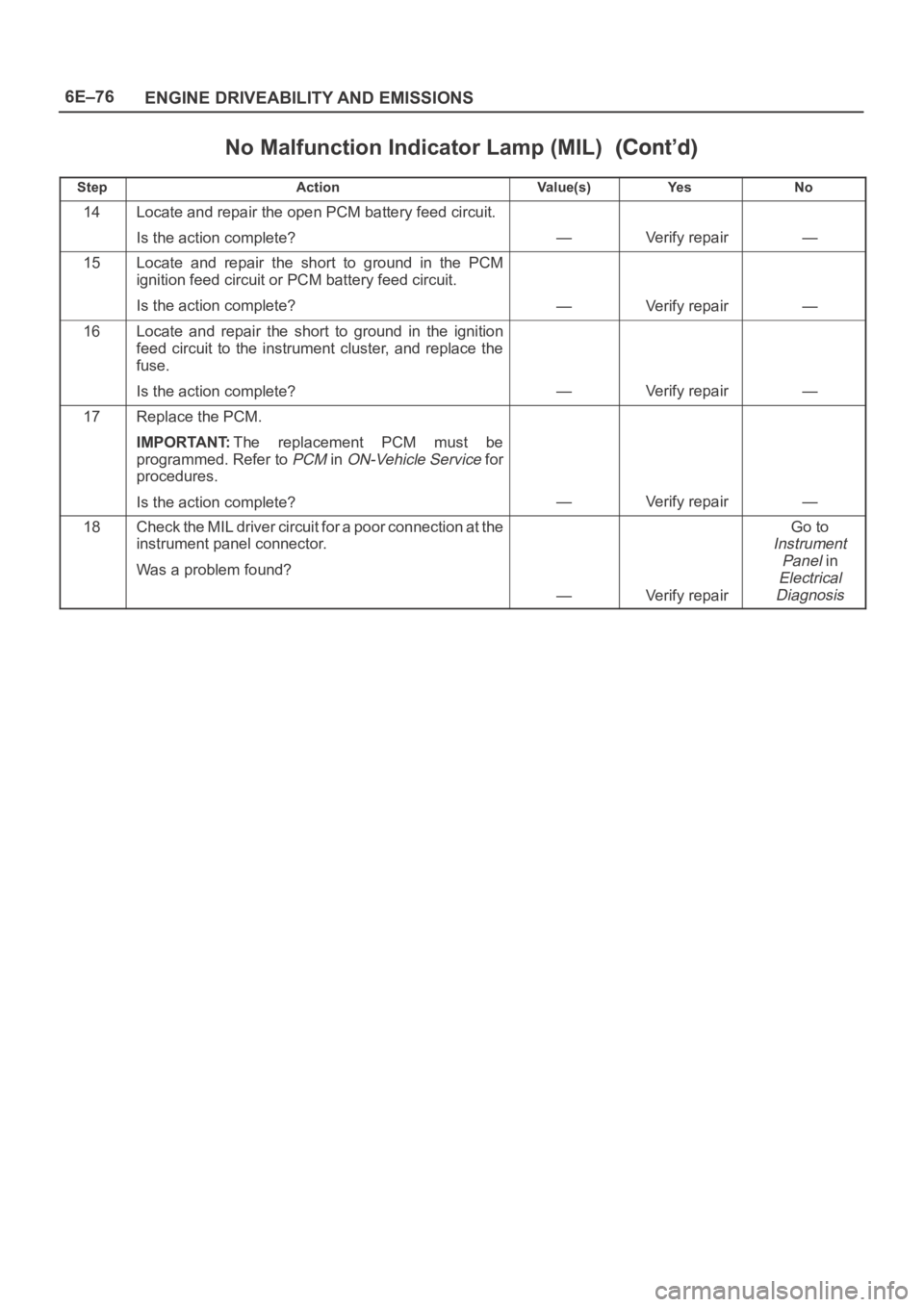
No Malfunction Indicator Lamp (MIL)
StepNo Ye s Va l u e ( s ) Action
14Locate and repair the open PCM battery feed circuit.
Is the action complete?
—Verify repair—
15Locate and repair the short to ground in the PCM
ignition feed circuit or PCM battery feed circuit.
Is the action complete?
—Verify repair—
16Locate and repair the short to ground in the ignition
feed circuit to the instrument cluster, and replace the
fuse.
Is the action complete?
—Verify repair—
17Replace the PCM.
IMPORTANT:The replacement PCM must be
programmed. Refer to
PCM in ON-Vehicle Service for
procedures.
Is the action complete?
—Verify repair—
18Check the MIL driver circuit for a poor connection at the
instrument panel connector.
Was a problem found?
—Verify repair
Go to
Instrument
Panel
in
Electrical
Diagnosis