1998 OPEL FRONTERA coolant level
[x] Cancel search: coolant levelPage 1392 of 6000
6E–275 ENGINE DRIVEABILITY AND EMISSIONS
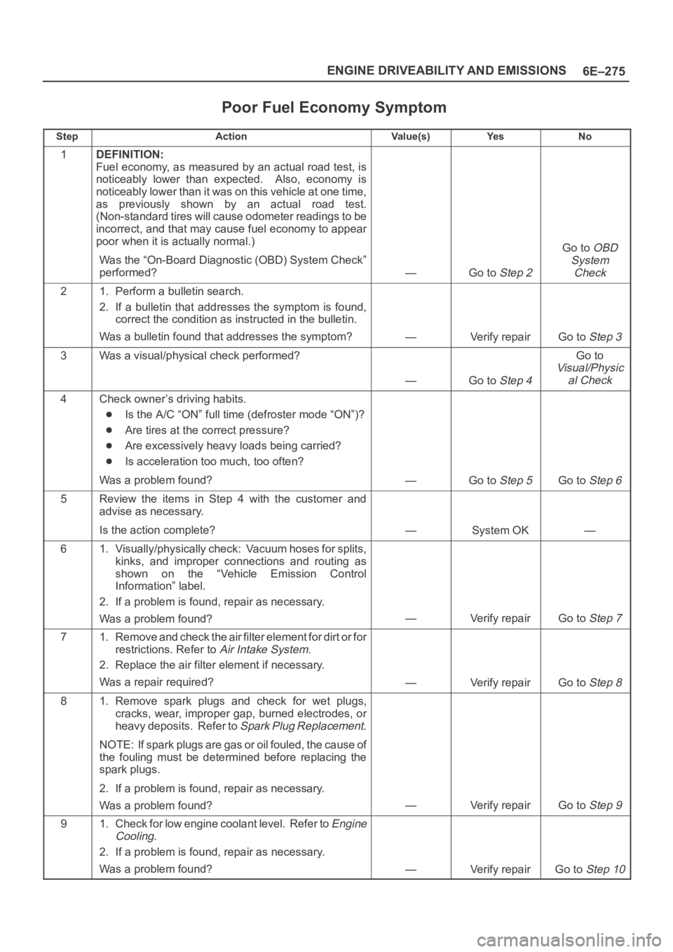
Poor Fuel Economy Symptom
StepActionVa l u e ( s )Ye sNo
1DEFINITION:
Fuel economy, as measured by an actual road test, is
noticeably lower than expected. Also, economy is
noticeably lower than it was on this vehicle at one time,
as previously shown by an actual road test.
(Non-standard tires will cause odometer readings to be
incorrect, and that may cause fuel economy to appear
poor when it is actually normal.)
Was the “On-Board Diagnostic (OBD) System Check”
performed?
—Go to Step 2
Go to OBD
System
Check
21. Perform a bulletin search.
2. If a bulletin that addresses the symptom is found,
correct the condition as instructed in the bulletin.
Was a bulletin found that addresses the symptom?
—Verify repairGo to Step 3
3Was a visual/physical check performed?
—Go to Step 4
Go to
Visual/Physic
al Check
4Check owner’s driving habits.
Is the A/C “ON” full time (defroster mode “ON”)?
Are tires at the correct pressure?
Are excessively heavy loads being carried?
Is acceleration too much, too often?
Was a problem found?
—Go to Step 5Go to Step 6
5Review the items in Step 4 with the customer and
advise as necessary.
Is the action complete?
—System OK—
61. Visually/physically check: Vacuum hoses for splits,
kinks, and improper connections and routing as
shown on the “Vehicle Emission Control
Information” label.
2. If a problem is found, repair as necessary.
Was a problem found?
—Verify repairGo to Step 7
71. Remove and check the air filter element for dirt or for
restrictions. Refer to
Air Intake System.
2. Replace the air filter element if necessary.
Was a repair required?
—Verify repairGo to Step 8
81. Remove spark plugs and check for wet plugs,
cracks, wear, improper gap, burned electrodes, or
heavy deposits. Refer to
Spark Plug Replacement.
NOTE: If spark plugs are gas or oil fouled, the cause of
the fouling must be determined before replacing the
spark plugs.
2. If a problem is found, repair as necessary.
Was a problem found?
—Verify repairGo to Step 9
91. Check for low engine coolant level. Refer to Engine
Cooling
.
2. If a problem is found, repair as necessary.
Was a problem found?
—Verify repairGo to Step 10
Page 1454 of 6000
6E–337 ENGINE DRIVEABILITY AND EMISSIONS
0018
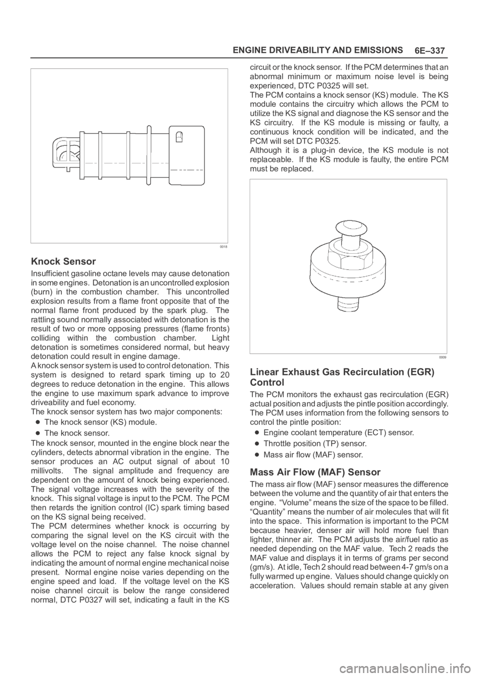
Knock Sensor
Insufficient gasoline octane levels may cause detonation
in some engines. Detonation is an uncontrolled explosion
(burn) in the combustion chamber. This uncontrolled
explosion results from a flame front opposite that of the
normal flame front produced by the spark plug. The
rattling sound normally associated with detonation is the
result of two or more opposing pressures (flame fronts)
colliding within the combustion chamber. Light
detonation is sometimes considered normal, but heavy
detonation could result in engine damage.
A knock sensor system is used to control detonation. This
system is designed to retard spark timing up to 20
degrees to reduce detonation in the engine. This allows
the engine to use maximum spark advance to improve
driveability and fuel economy.
The knock sensor system has two major components:
The knock sensor (KS) module.
The knock sensor.
The knock sensor, mounted in the engine block near the
cylinders, detects abnormal vibration in the engine. The
sensor produces an AC output signal of about 10
millivolts. The signal amplitude and frequency are
dependent on the amount of knock being experienced.
The signal voltage increases with the severity of the
knock. This signal voltage is input to the PCM. The PCM
then retards the ignition control (IC) spark timing based
on the KS signal being received.
The PCM determines whether knock is occurring by
comparing the signal level on the KS circuit with the
voltage level on the noise channel. The noise channel
allows the PCM to reject any false knock signal by
indicating the amount of normal engine mechanical noise
present. Normal engine noise varies depending on the
engine speed and load. If the voltage level on the KS
noise channel circuit is below the range considered
normal, DTC P0327 will set, indicating a fault in the KScircuit or the knock sensor. If the PCM determines that an
abnormal minimum or maximum noise level is being
experienced, DTC P0325 will set.
The PCM contains a knock sensor (KS) module. The KS
module contains the circuitry which allows the PCM to
utilize the KS signal and diagnose the KS sensor and the
KS circuitry. If the KS module is missing or faulty, a
continuous knock condition will be indicated, and the
PCM will set DTC P0325.
Although it is a plug-in device, the KS module is not
replaceable. If the KS module is faulty, the entire PCM
must be replaced.
0009
Linear Exhaust Gas Recirculation (EGR)
Control
The PCM monitors the exhaust gas recirculation (EGR)
actual position and adjusts the pintle position accordingly.
The PCM uses information from the following sensors to
control the pintle position:
Engine coolant temperature (ECT) sensor.
Throttle position (TP) sensor.
Mass air flow (MAF) sensor.
Mass Air Flow (MAF) Sensor
The mass air flow (MAF) sensor measures the difference
between the volume and the quantity of air that enters the
engine. “Volume” means the size of the space to be filled.
“Quantity” means the number of air molecules that will fit
into the space. This information is important to the PCM
because heavier, denser air will hold more fuel than
lighter, thinner air. The PCM adjusts the air/fuel ratio as
needed depending on the MAF value. Tech 2 reads the
MAF value and displays it in terms of grams per second
(gm/s). At idle, Tech 2 should read between 4-7 gm/s on a
fully warmed up engine. Values should change quickly on
acceleration. Values should remain stable at any given
Page 1456 of 6000
6E–339 ENGINE DRIVEABILITY AND EMISSIONS
0005
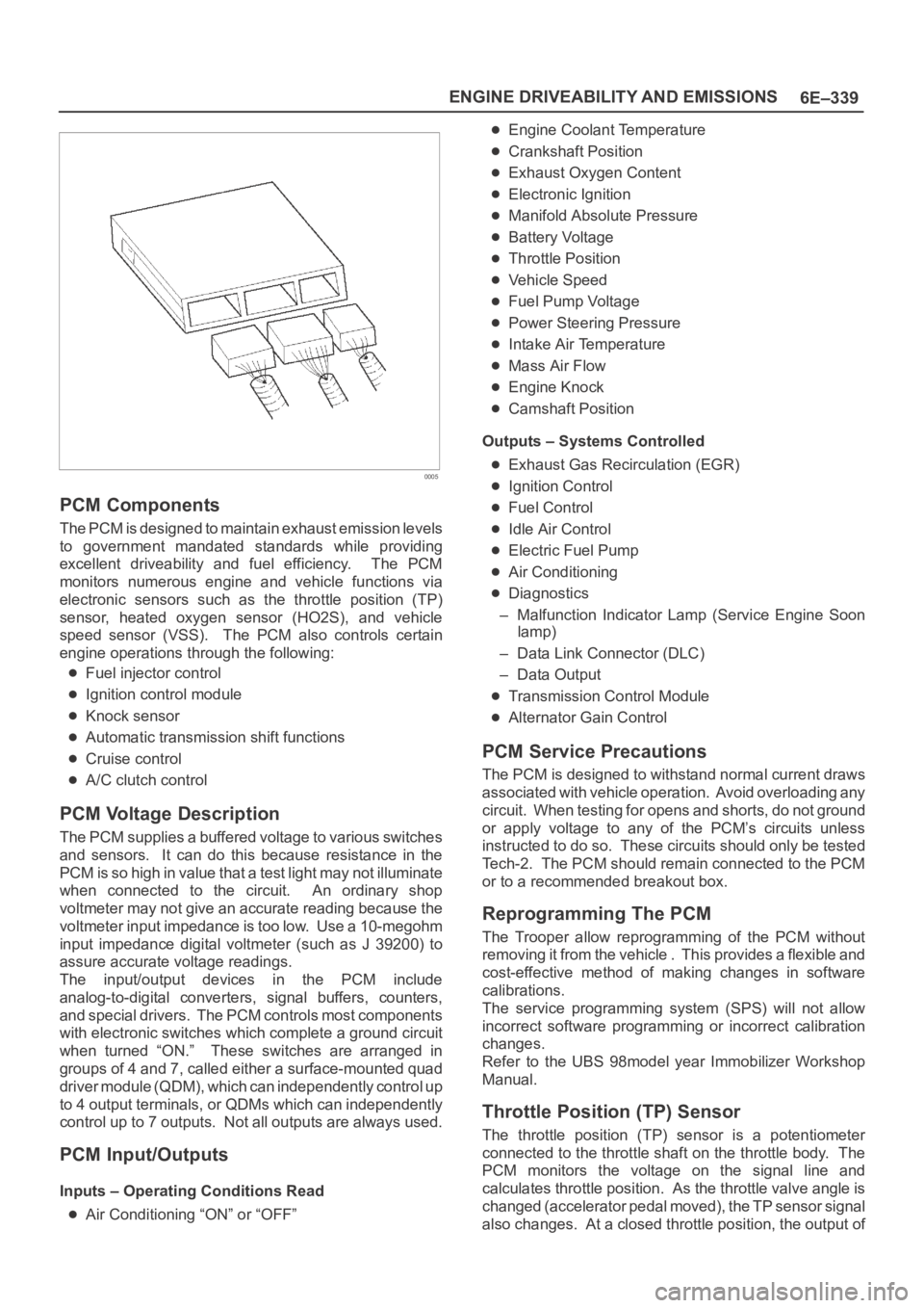
PCM Components
The PCM is designed to maintain exhaust emission levels
to government mandated standards while providing
excellent driveability and fuel efficiency. The PCM
monitors numerous engine and vehicle functions via
electronic sensors such as the throttle position (TP)
sensor, heated oxygen sensor (HO2S), and vehicle
speed sensor (VSS). The PCM also controls certain
engine operations through the following:
Fuel injector control
Ignition control module
Knock sensor
Automatic transmission shift functions
Cruise control
A/C clutch control
PCM Voltage Description
The PCM supplies a buffered voltage to various switches
and sensors. It can do this because resistance in the
PCM is so high in value that a test light may not illuminate
when connected to the circuit. An ordinary shop
voltmeter may not give an accurate reading because the
voltmeter input impedance is too low. Use a 10-megohm
input impedance digital voltmeter (such as J 39200) to
assure accurate voltage readings.
The input/output devices in the PCM include
analog-to-digital converters, signal buffers, counters,
and special drivers. The PCM controls most components
with electronic switches which complete a ground circuit
when turned “ON.” These switches are arranged in
groups of 4 and 7, called either a surface-mounted quad
driver module (QDM), which can independently control up
to 4 output terminals, or QDMs which can independently
control up to 7 outputs. Not all outputs are always used.
PCM Input/Outputs
Inputs – Operating Conditions Read
Air Conditioning “ON” or “OFF”
Engine Coolant Temperature
Crankshaft Position
Exhaust Oxygen Content
Electronic Ignition
Manifold Absolute Pressure
Battery Voltage
Throttle Position
Vehicle Speed
Fuel Pump Voltage
Power Steering Pressure
Intake Air Temperature
Mass Air Flow
Engine Knock
Camshaft Position
Outputs – Systems Controlled
Exhaust Gas Recirculation (EGR)
Ignition Control
Fuel Control
Idle Air Control
Electric Fuel Pump
Air Conditioning
Diagnostics
– Malfunction Indicator Lamp (Service Engine Soon
lamp)
– Data Link Connector (DLC)
– Data Output
Transmission Control Module
Alternator Gain Control
PCM Service Precautions
The PCM is designed to withstand normal current draws
associated with vehicle operation. Avoid overloading any
circuit. When testing for opens and shorts, do not ground
or apply voltage to any of the PCM’s circuits unless
instructed to do so. These circuits should only be tested
Tech-2. The PCM should remain connected to the PCM
or to a recommended breakout box.
Reprogramming The PCM
The Trooper allow reprogramming of the PCM without
removing it from the vehicle . This provides a flexible and
cost-effective method of making changes in software
calibrations.
The service programming system (SPS) will not allow
incorrect software programming or incorrect calibration
changes.
Refer to the UBS 98model year Immobilizer Workshop
Manual.
Throttle Position (TP) Sensor
The throttle position (TP) sensor is a potentiometer
connected to the throttle shaft on the throttle body. The
PCM monitors the voltage on the signal line and
calculates throttle position. As the throttle valve angle is
changed (accelerator pedal moved), the TP sensor signal
also changes. At a closed throttle position, the output of
Page 1466 of 6000
6E–349 ENGINE DRIVEABILITY AND EMISSIONS
Damage during re-gapping can happen if the gapping
tool is pushed against the center electrode or the
insulator around it, causing the insulator to crack.
When re-gapping a spark plug, make the adjustment
by bending only the ground side terminal, keeping the
tool clear of other parts.
”Heat shock” breakage in the lower insulator tip
generally occurs during several engine operating
conditions (high speeds or heavy loading) and may be
caused by over-advanced timing or low grade fuels.
Heat shock refers to a rapid increase in the tip
temperature that causes the insulator material to
crack.
Spark plugs with less than the recommended amount of
service can sometimes be cleaned and re-gapped , then
returned to service. However, if there is any doubt about
the serviceability of a spark plug, replace it. Spark plugs
with cracked or broken insulators should always be
replaced.
A/C Clutch Diagnosis
A/C Clutch Circuit Operation
A 12-volt signal is supplied to the A/C request input of the
PCM when the A/C is selected through the A/C control
switch.
The A/C compressor clutch relay is controlled through the
PCM. This allows the PCM to modify the idle air control
position prior to the A/C clutch engagement for better idle
quality. If the engine operating conditions are within their
specified calibrated acceptable ranges, the PCM will
enable the A/C compressor relay. This is done by
providing a ground path for the A/C relay coil within the
PCM. When the A/C compressor relay is enabled,
battery voltage is supplied to the compressor clutch coil.
The PCM will enable the A/C compressor clutch
whenever the engine is running and the A/C has been
requested. The PCM will not enable the A/C compressor
clutch if any of the following conditions are met:
The throttle is greater than 90%.
The engine speed is greater than 6315 RPM.
The ECT is greater than 119C (246F).
The IAT is less than 5C (41F).
The throttle is more than 80% open.
A/C Clutch Circuit Purpose
The A/C compressor operation is controlled by the
powertrain control module (PCM) for the following
reasons:
It improvises idle quality during compressor clutch
engagement.
It improvises wide open throttle (WOT) performance.
It provides A/C compressor protection from operation
with incorrect refrigerant pressures.
The A/C electrical system consists of the following
components:
The A/C control head.
The A/C refrigerant pressure switches.
The A/C compressor clutch.
The A/C compressor clutch relay.
The PCM.
A/C Request Signal
This signal tells the PCM when the A/C mode is selected
at the A/C control head. The PCM uses this to adjust the
idle speed before turning on the A/C clutch. The A/C
compressor will be inoperative if this signal is not
available to the PCM.
Refer to
A/C Clutch Circuit Diagnosis for A/C wiring
diagrams and diagnosis for A/C electrical system.
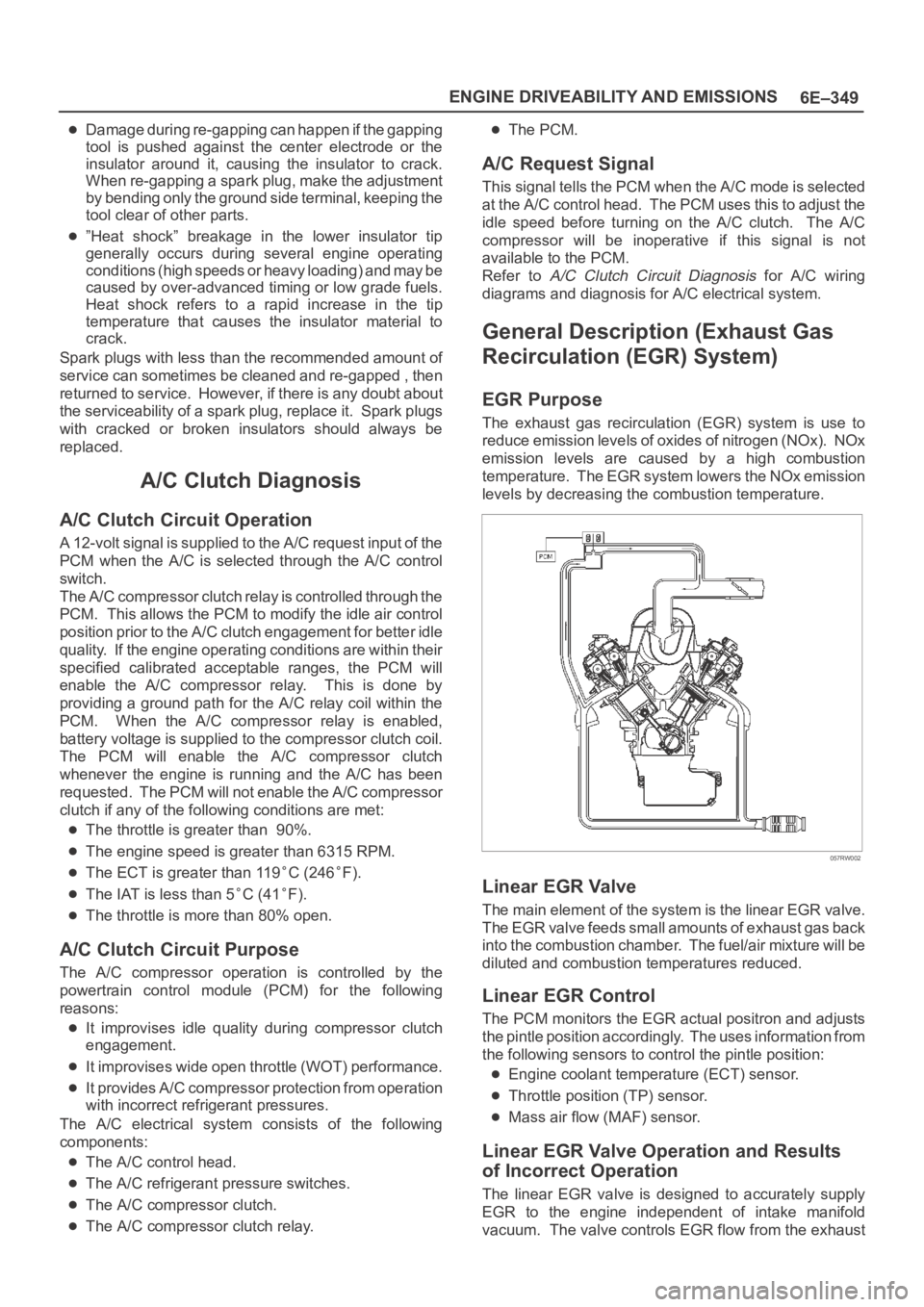
General Description (Exhaust Gas
Recirculation (EGR) System)
EGR Purpose
The exhaust gas recirculation (EGR) system is use to
reduce emission levels of oxides of nitrogen (NOx). NOx
emission levels are caused by a high combustion
temperature. The EGR system lowers the NOx emission
levels by decreasing the combustion temperature.
057RW002
Linear EGR Valve
The main element of the system is the linear EGR valve.
The EGR valve feeds small amounts of exhaust gas back
into the combustion chamber. The fuel/air mixture will be
diluted and combustion temperatures reduced.
Linear EGR Control
The PCM monitors the EGR actual positron and adjusts
the pintle position accordingly. The uses information from
the following sensors to control the pintle position:
Engine coolant temperature (ECT) sensor.
Throttle position (TP) sensor.
Mass air flow (MAF) sensor.
Linear EGR Valve Operation and Results
of Incorrect Operation
The linear EGR valve is designed to accurately supply
EGR to the engine independent of intake manifold
vacuum. The valve controls EGR flow from the exhaust
Page 1743 of 6000

6A – 10 ENGINE MECHANICAL
8. Check the engine oil level and replenish to the
specified level if required.
9. Start the engine and check for oil leakage from the
main oil filter.
FUEL SYSTEM
Fuel filter
Replacement Procedure
1. Loosen the used fuel filter by turning it
counterclockwise with the filter wrench.
Filter Wrench : 5-8840-0203-0
2. Clean the filter cover fitting faces.
This will allow the new fuel filter to seat properly.
3. Apply a light coat of engine oil to the O-ring.
4. Turn the fuel filter until the sealing face comes in
contact with the O-ring.
5. Turn the fuel filter with a filter wrench 2/3 of a turn
until sealed.
Filter Wrench: 5-8840-0203-0Legend
(1) Priming pump
6. Operate the priming pump until the air is discharged
completely from fuel system.
NOTE: The use of an Isuzu genuine fuel filter is
strongly recommended.
COOLING SYSTEM
Coolant Level
Check the coolant level and replenish the radiator
reserve tank as necessary.
If the coolant level falls below the “‘MIN” line, carefully
check the cooling system for leakage. Then add
enough coolant to bring the level up to the “MAX” line.
NOTE: Do not overfill the reserve tank.
012RW112
012RW078
1
012RW111
012RW080
Page 1744 of 6000
ENGINE MECHANICAL 6A – 11
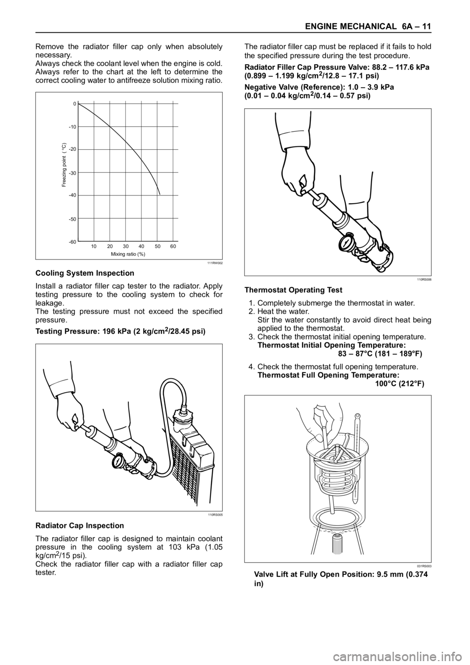
Remove the radiator filler cap only when absolutely
necessary.
Always check the coolant level when the engine is cold.
Always refer to the chart at the left to determine the
correct cooling water to antifreeze solution mixing ratio.
Cooling System Inspection
Install a radiator filler cap tester to the radiator. Apply
testing pressure to the cooling system to check for
leakage.
The testing pressure must not exceed the specified
pressure.
Testing Pressure: 196 kPa (2 kg/cm
2/28.45 psi)
Radiator Cap Inspection
The radiator filler cap is designed to maintain coolant
pressure in the cooling system at 103 kPa (1.05
kg/cm
2/15 psi).
Check the radiator filler cap with a radiator filler cap
tester.The radiator filler cap must be replaced if it fails to hold
the specified pressure during the test procedure.
Radiator Filler Cap Pressure Valve: 88.2 – 117.6 kPa
(0.899 – 1.199 kg/cm
2/12.8 – 17.1 psi)
Negative Valve (Reference): 1.0 – 3.9 kPa
(0.01 – 0.04 kg/cm
2/0.14 – 0.57 psi)
Thermostat Operating Test
1. Completely submerge the thermostat in water.
2. Heat the water.
Stir the water constantly to avoid direct heat being
applied to the thermostat.
3. Check the thermostat initial opening temperature.
Thermostat Initial Opening Temperature:
83 – 87°C (181 – 189°F)
4. Check the thermostat full opening temperature.
Thermostat Full Opening Temperature:
100°C (212°F)
Valve Lift at Fully Open Position: 9.5 mm (0.374
in)0
-10
-20
-30
-40
-50
-60
10 20 30
Mixing ratio (%)
Freezing point (
C)
40 50 60
111RW002
110RS005
110RS006
031RS003
Page 1768 of 6000

ENGINE MECHANICAL 6A – 35
INTAKE MANIFOLD
REMOVAL
1. Drain engine coolant and disconnect water hose
from thermostat hosing.
2. Remove intercooler assembly
Refer to “Intercooler” in this manual.
3. Remove bracket bolt of oil level gauge guide tube.
4. Remove PCV Hose.
5. Remove hoses from EGR, EGR vacuum sensor
and inlet/outlet of heater.
6. Disconnect harness connector form MAP sensor,
EGR vacuum sensor, ETC sensor, water
temperature unit, IAT sensor and EVRV.
7. Remove high pressure oil pipe.
8. Remove the two way valve.
9. Remove fuel pipe from between intake manifold
and high pressure oil pump.
10. Remove fixing bolts and nuts on the intake
manifold, then remove the intake manifold
assembly.
INSTALLATION
1. Install the intake manifold, tighten bolts and nuts to
the specified torque.
Torque : 20 Nꞏm (2.0 kgꞏm/14.5 lb ft) for bolt and nut
2. Install the fuel pipe and tighten to the specified
torque.To r q u e :
M16 bolt (apply engine oil) 4 Nꞏm (0.4 kgꞏm/2.9
lb ft)
Cap nut (M10) 13Nꞏm (1.3 kgꞏm/9.4 lb ft)
Fuel pipe (M10 apply engine oil) 14 Nꞏm (1.4
kgꞏm/10 lb ft)
3. Install two way valve.
Torque : 20 Nꞏm (2.0 kgꞏm/14.5 lb ft)
4. Fill with about 300 cc of engine oil from the high
pressure oil pipe installation port of the oil rail using
an oil filler. If assembled without filling the oil rail
with oil, the time for starting the engine will be
longer.
5. Install the high pressure oil pipe immediately and
tighten the sleeve nut to the specified torque.
Torque : 80 Nꞏm (8 kgꞏm/57.9 lb ft)
6. Reconnect harness connector to MAP sensor, EGR
vacuum sensor, ETC sensor, Water temperature
unit, IAT sensor and EVRV.
7. Connect the hoses to EGR valve, EGR vacuum
sensor, and water inlet/outlet pipe for heater.
8. Connect PCV hose.
9. Install the oil level gauge guide tube and tighten
bracket bolt.
10. Install the intercooler assembly.
Refer to “Intercooler” in this manual.
11. Connect the hose to the thermostat housing and fill
with engine coolant.
For Europe
2
1
3
3 1 42
025R200005
Legend
(1) Intake Manifold
(2) Throttle Valve Assembly
(3) EGR Valve
(4) Gasket
Page 1777 of 6000

6A – 44 ENGINE MECHANICAL
REMOVAL
1. Disconnect battery ground cable.
2. Drain engine coolant.
3. Remove air cleaner and air duct.
4. Remove intercooler assembly.
Refer to “Intercooler” in this manual.
5. Remove oil level gauge guide assembly.
6. Remove PCV hose.
7. Remove EGR vacuum hose.
8. Disconnect harness connector around the cylinder
head.
9. Remove A/C compressor assembly.
10. Remove A/C compressor bracket.
11. Remove generator assembly and take out fan belt.
12. Remove heat protector and remove valve
assembly.
13. Remove water hose and oil pipe from turbocharger.
14. Remove turbocharger assembly.
15. Remove water hose between thermostat and
radiator.
16. Remove cylinder head noise insulator cover.
NOTE: Do not make damage to the harness.
17. Remove high pressure pipe.
18. Remove timing belt cover.
19. Remove CMP sensor bracket.
20. Remove timing belt tensioner and remove timing
belt.
21. Remove camshaft pulley.
22. Remove front plate.
23. Remove water pipe between cylinder head and
water pump.
24. Remove fuel pipe between fuel pump and intake
manifold.
25. Remove fuel return pipe.
26. Remove intake manifold assembly.
27. Disconnect glow plug wiring and remove glow plug.
28. Remove cylinder head cover.
29. Drain oil from oil rail.
30. Disconnect injector harness connector.
31. Disconnect harness connector from oil pressure
sensor and oil temperature sensor on the oil rail.
32. Disconnect injector harness assembly.
33. Remove injector clamp.
34. Remove injector spacer (If equipped.).
35. Remove injector assembly.
36. Remove oil rail assembly.
37. Remove camshaft carrier.
38. Remove cylinder head assembly.
39. Remove cylinder gasket.
INSTALLATION
1. Install cylinder head gasket with top mark up.
NOTE: Determine cylinder head gasket grade by
measuring projection of piston head.2. Selection cylinder head gasket.
1) Measure the piston head projection by dial
gauge.
2) Measure the projection of piston head at the
nearest possible point to the cylinder bore.
3) Obtain the largest measurement from among all
cylinders.
4) Determine cylinder head gasket grade by
maximum value of measuring projection of
piston head.
Legend
(1) Top Mark
(2) Grade Mark
012RW073
2 1
011RW043