1998 OPEL FRONTERA coolant level
[x] Cancel search: coolant levelPage 2121 of 6000
6E–228
4JX1–TC ENGINE DRIVEABILITY AND EMISSIONS
General Description (Air Induction)
Air Induction System
The air induction system filters contaminants from the
outside air, and directs the progress of the air as it is
drawn into the engine. A remote-mounted air cleaner
prevents dirt and debris in the air from entering the
engine. The air duct assembly routes filtered air to the
throttle body. Air enters the engine by to following steps:
1. Through the throttle body.
2. Into the intake manifold.
3. Through the cylinder head intake ports.
4. Into the cylinders.
General Description (Fuel Metering)
Deceleration Mode
The ECM reduces the amount of fuel injected when it
detects a decrease in the Accelerator position.
Fuel Injector
Fuel injector comprises the solenoid, hydraulic line, and
fuel line. Fuel injection is controlled by the continuity time
signal and continuity start timing signal from ECM to the
solenoid
ECM determines the running conditions of engine by
input signals such as engine speed. Accelerator throttle
valve opening, and engine coolant temperature, thereby
to send the solenoid the best suited signal to the engine
status. When current is carried to the solenoid, the
armature opens the poppet valve to alow high pressure oil
to run into the injector. Under the pressure of the oil, the
piston and plunger are depressed to compress the fuel in
the combustion chamber of the plunger. Specifically, the
pressure of the fuel compressed is increased by a piston
top/ plunger bottom area ratio over the pressure of high
pressure oil, thereby lifting the fuel nozzle end needle for
injecting fuel.
Fuel Metering System Components
The fuel metering system is made up of the following
parts:
The fuel injectors.
The intake throttle body.
The Accelerator position (AP) sensor
The ECM.
The crankshaft position (CKP) sensor.
The camshaft position (CMP) sensor.
Basic System Operation
Fuel is supplied through fuel filter to the fuel pump.
The fuel pump is installed to the oil pump, and fuel is
forced, through the fuel pump outlet, pipe and cylinder
head inside, into the fuel injector.
An orifice is provided at the rear fuel outlet of cylinder
head to control the pressure of oil.The injector is controlled by ECM which gives
opening/closing commands to the solenoid installed on
the top of the injector. Opening/closing operation of the
pressurized engine oil circuit of the injector controls fuel
injection quantity, fuel injection timing, etc.
A/C Clutch Diagnosis
A/C Request Signal
This signal tells the ECM when the A/C mode is selected
at the A/C control head. The ECM uses this to adjust the
idle speed.
Refer to
A/C Clutch Circuit Diagnosis for A/C wiring
diagrams and diagnosis for A/C electrical system.
General Description Exhaust Gas
Recirculation (EGR) System
EGR Purpose
The exhaust gas recirculation (EGR) system is use to
reduce emission levels of oxides of nitrogen (NOx). NOx
emission levels are caused by a high combustion
temperature. The EGR system lowers the NOx emission
levels by decreasing the combustion temperature.
The ECM uses information from the following sensors to
control EGR valve boost pressure.
ECT
ITP
Engine Speed
AP sensor
Page 2149 of 6000

6J – 8 INDUCTION
7. Water inlet pipe.
1) Install water inlet pipe with a new gasket, tighten
bolts to the specified torque.
Torque: 9 Nꞏm (0.9 kgꞏm / 6.5 lb ft)
8. Install intercooler assembly.
Refer to “Intercooler” in this manual.
9. Install air cleaner cover with air duct.
10. Fill engine coolant to full level.
11. Install battery and connect battery cable.
For Europe
025R200007
Page 2152 of 6000

INDUCTION 6J – 11
INTAKE MANIFOLD
REMOVAL
1. Drain engine coolant and remove water hose from
thermostat housing
2. Remove intercooler assembly.
3. Remove bracket fixing bolt of oil level gauge guide
tube.
4. Remove PCV hose.
5. Remove hoses from EGR valve, EGR vacuum
sensor and outlet of heater unit.
6. Disconnect harness connector from MAP sensor,
EGR vacuum sensor, ETC sensor, Water
temperature unit, IAT sensor and EVRV.
7. Remove high pressure oil pipe.
8. Remove two way check valve.
9. Remove fuel pipe.
10. Remove fixing bolts and nuts of intake manifold,
remove intake manifold assembly.
Legend
(1) Intake manifold
(2) Fixing portion of throttle valve
(3) EGR passage
(4) EGR valve
For Europe
2
1
3
3 1 42
Legend
(1) Intake Manifold
(2) Throttle Valve Assembly
(3) EGR Valve
(4) Gasket
025R200005
3124
025RW031
Page 2153 of 6000

6J – 12 INDUCTION
INSPECTION AND RAPAIR
1. Visually check for cracks/clogs inside intake
manifold.
2. If foreign material is observed, it should be taken
out, and if there are some cracks on the intake
manifold, it must be replaced.
INSTALLATION
1. Install the intake manifold assembly, tighten bolts
and to the specified torque.
Torque: 20 Nꞏm (2.0 kgꞏm / 14.5 lb ft) for bolt
Torque: 20 Nꞏm (2.0 kgꞏm / 14.5 lb ft) for nut
2. Install fuel pipe.
Torque: 4 Nꞏm (0.4 kgꞏm / 2.9 lb ft) for M16 nut
(Apply engine oil)
Torque: 13 Nꞏm (1.3 kgꞏm / 9.4 lb ft) for M10 cap nut
Torque: 14 Nꞏm (1.4 kgꞏm / 10 lb ft) for M10
(Apply engine oil)
3. Install two way check valve.
Torque: 20 Nꞏm (2.0 kgꞏm / 14.5 lb ft)
4. Fill with about 300 cc of engine oil from the high
pressure oil pipe installation port of the oil rail using
an oil filler.
If assembled without filling the oil rail with oil, the
time for engine starting will be longer.
5. Install high pressure oil pipe, then tighten sleeve nut
to the specified torque.
Torque: 29 Nꞏm (3.0 kgꞏm / 21.7 lb ft)
6. Reconnect harness connector to MAP sensor, EGR
vacuum sensor, ETC sensor, Water thermo unit,
IAT sensor and EVRV sensor.
7. Install hoses to EGR valve, EGR vacuum sensor
and Water outlet of heater.
8. Connect PCV hose.
9. Install oil level gauge guide and fix it.
10. Install intercooler assembly.
Refer to “Intercooler” in this manual.
11. Install water hose to thermostat housing and fill with
engine coolant.
Model of Turbocharger IHI RHF5
Turbine Maximum Speed 180,000 rpm
Maximum Inlet Gas Temperature 800 °C (1472 °F)
Vibration Peak (G) criteria Maximum 4 (G) at Turbine Rotor Speed 140,000 rpm
Tolerance Limit of Compressor Blade Height Less then 0.5 mm (0.0197 in)
MAIN DATA AND SPECIFICATIONS
Page 2177 of 6000
7A–23 AUTOMATIC TRANSMISSION (4L30–E)
Stall Test
The stall test allows you to check the transmission for
internal abrasion and the one way clutch for slippage.
Torque converter performance can also be evaluated.
The stall test results together with the road test results will
identify transmission components requiring servicing or
adjustment.
Stall Test Procedure:
1. Check the level of the engine coolant, the engine oil,
and the automatic transmission fluid. Replenish if
necessary.
2. Block the wheels and set the parking brake.
3. Connect a tachometer to the engine.
4. Start the engine and allow it to idle until the engine
coolant temperature reaches 70 – 80
C (158 –
176
F).
5. Hold the brake pedal down as far as it will go.
6. Place the selector in the “D” range.
7. Gradually push the accelerator pedal to the floor.
The throttle valve will be fully open.
Note the engine speed at which the tachometer
needle stabilizes.
Stall Speed : 2,100
150 rpm
NOTE: Do not continuously run this test longer than 5
seconds.
8. Release the accelerator pedal.
9. Place the selector in the “N” range.
10. Run the engine at 1,200 rpm for one minute.
This will cool the transmission fluid.
11. Repeat Steps 7 – 10 for the “3”, “2”, “L” and “R”
ranges.
Line Pressure Test
The line pressure test checks oil pump and control valve
pressure regulator valve function. It will also detect oil
leakage.
Line Pressure Test Procedure:
1. Check the level of the engine coolant, the engine oil,
and the automatic transmission fluid.
Replenish if required.
2. Block the wheels and set the parking brake.
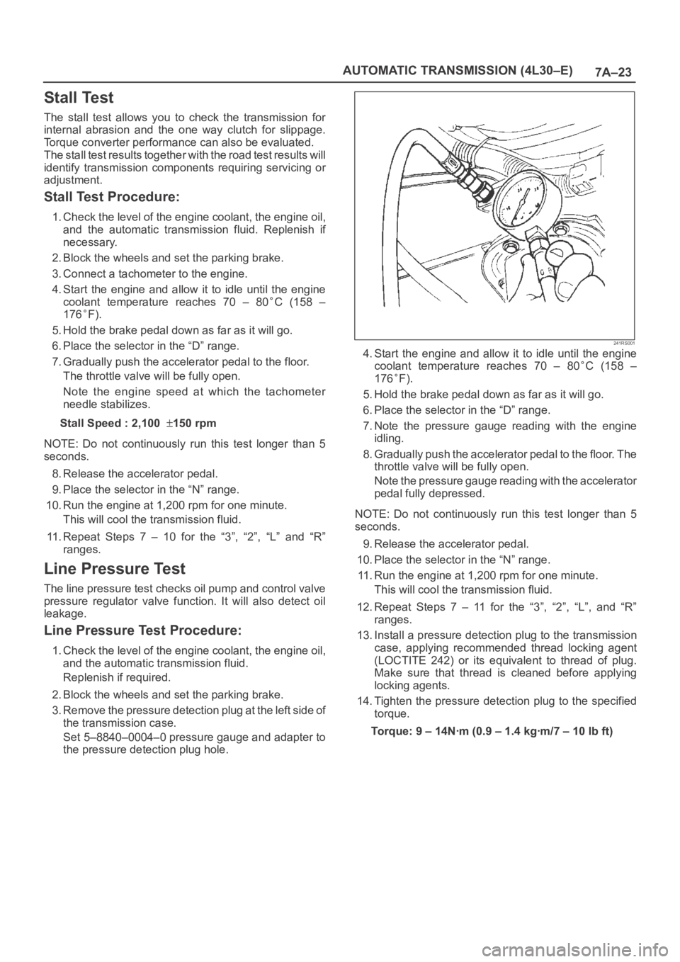
3. Remove the pressure detection plug at the left side of
the transmission case.
Set 5–8840–0004–0 pressure gauge and adapter to
the pressure detection plug hole.
241RS001
4. Start the engine and allow it to idle until the engine
coolant temperature reaches 70 – 80
C (158 –
176
F).
5. Hold the brake pedal down as far as it will go.
6. Place the selector in the “D” range.
7. Note the pressure gauge reading with the engine
idling.
8. Gradually push the accelerator pedal to the floor. The
throttle valve will be fully open.
Note the pressure gauge reading with the accelerator
pedal fully depressed.
NOTE: Do not continuously run this test longer than 5
seconds.
9. Release the accelerator pedal.
10. Place the selector in the “N” range.
11. Run the engine at 1,200 rpm for one minute.
This will cool the transmission fluid.
12. Repeat Steps 7 – 11 for the “3”, “2”, “L”, and “R”
ranges.
13. Install a pressure detection plug to the transmission
case, applying recommended thread locking agent
(LOCTITE 242) or its equivalent to thread of plug.
Make sure that thread is cleaned before applying
locking agents.
14. Tighten the pressure detection plug to the specified
torque.
Torque:9–14Nꞏm(0.9–1.4kgꞏm/7–10lbft)
Page 4507 of 6000
6A–11
ENGINE MECHANICAL
Condition CorrectionPossible cause
Engine overheatingLevel of Engine Coolant too lowReplenish
Fan clutch defectiveReplace
Incorrect fan installedReplace
Thermostat defectiveReplace
Engine Coolant pump defectiveCorrect or replace
Radiator cloggedClean or replace
Radiator filler cap defectiveReplace
Level of oil in engine crankcase too
low or wrong engine oilChange or replenish
Resistance in exhaust system
increasedClean exhaust system or replace
defective parts
Throttle Position Sensor adjustment
incorrectReplace with Throttle Valve ASM
Throttle Position Sensor circuit open
or shortedCorrect or replace
Cylinder head gasket damagedReplace
Engine overcoolingThermostat defectiveReplace (Use a thermostat set to
open at 82
C (180F))
Engine lacks compression————Refer to Hard Start
OthersTire inflation pressure abnormalAdjust to recommended pressures
Brake dragAdjust
Clutch slippingAdjust or replace
Level of oil in engine crankcase too
highCorrect level of engine oil
Exhaust Gas Recirculation Valve
defectiveReplace
Engine Noisy
Abnormal engine noise often consists of various noises
originating in rotating parts, sliding parts and othermoving parts of the engine. It is, therefore, advisable to
locate the source of noise systematically.
Condition
Possible causeCorrection
Noise from crank journals or from
crank bearings
(Faulty crank journals and crankOil clearance increased due to worn
crank journals or crank bearingsReplace crank bearings and
crankshaft or regrind crankshaft and
install the undersize bearing
yj
bearings usually make dull noise that
becomes more evident when
accelerating)Crankshaft out of roundReplace crank bearings and
crankshaft or regrind crankshaft and
install the undersize bearing
Crank bearing seizedCrank bearing seized. Replace crank
bearings and crankshaft or regrind
crankshaft and install the undersize
bearing
Troubleshooting Procedure
Short out each spark plug in sequence using insulated
spark plug wire removers. Locate cylinder with defectivebearing by listening for abnormal noise that stops when
spark plug is shorted out.
Page 4535 of 6000
6A–39
ENGINE MECHANICAL
Valve Stem Oil Controller , Valve Spring and Valve Guide
Removal
1. Disconnect battery ground cable.
2. Drain engine oil.
Drain engine coolant.
3. Remove cylinder head assembly.
Refer to removal procedure for Cylinder Head in
this manual.
4. Remove camshaft.
Refer to removal procedure for Camshaft in this
manual.
5. Remove tappets with shim.
NOTE: Do not damage shim surface.
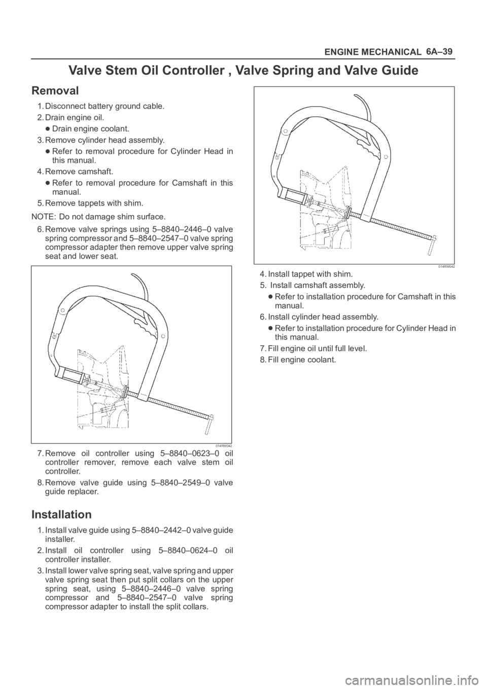
6. Remove valve springs using 5–8840–2446–0 valve
spring compressor and 5–8840–2547–0 valve spring
compressor adapter then remove upper valve spring
seat and lower seat.
014RW042
7. Remove oil controller using 5–8840–0623–0 oil
controller remover, remove each valve stem oil
controller.
8. Remove valve guide using 5–8840–2549–0 valve
guide replacer.
Installation
1. Install valve guide using 5–8840–2442–0 valve guide
installer.
2. Install oil controller using 5–8840–0624–0 oil
controller installer.
3. Install lower valve spring seat, valve spring and upper
valve spring seat then put split collars on the upper
spring seat, using 5–8840–2446–0 valve spring
compressor and 5–8840–2547–0 valve spring
compressor adapter to install the split collars.
014RW042
4. Install tappet with shim.
5. Install camshaft assembly.
Refer to installation procedure for Camshaft in this
manual.
6. Install cylinder head assembly.
Refer to installation procedure for Cylinder Head in
this manual.
7. Fill engine oil until full level.
8. Fill engine coolant.
Page 4598 of 6000
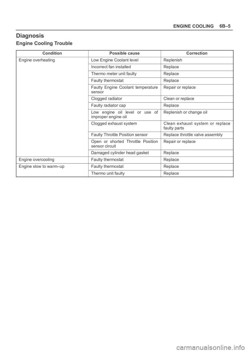
ENGINE COOLING6B–5
Diagnosis
Engine Cooling Trouble
ConditionPossible causeCorrection
Engine overheatingLow Engine Coolant levelReplenish
Incorrect fan installedReplace
Thermo meter unit faultyReplace
Faulty thermostatReplace
Faulty Engine Coolant temperature
sensorRepair or replace
Clogged radiatorClean or replace
Faulty radiator capReplace
Low engine oil level or use of
improper engine oilReplenish or change oil
Clogged exhaust systemClean exhaust system or replace
faulty parts
Faulty Throttle Position sensorReplace throttle valve assembly
Open or shorted Throttle Position
sensor circuitRepair or replace
Damaged cylinder head gasketReplace
Engine overcoolingFaulty thermostatReplace
Engine slow to warm–upFaulty thermostatReplace
Thermo unit faultyReplace