1998 OPEL FRONTERA Gas
[x] Cancel search: GasPage 1934 of 6000
6E–41 4JX1–TC ENGINE DRIVEABILITY AND EMISSIONS
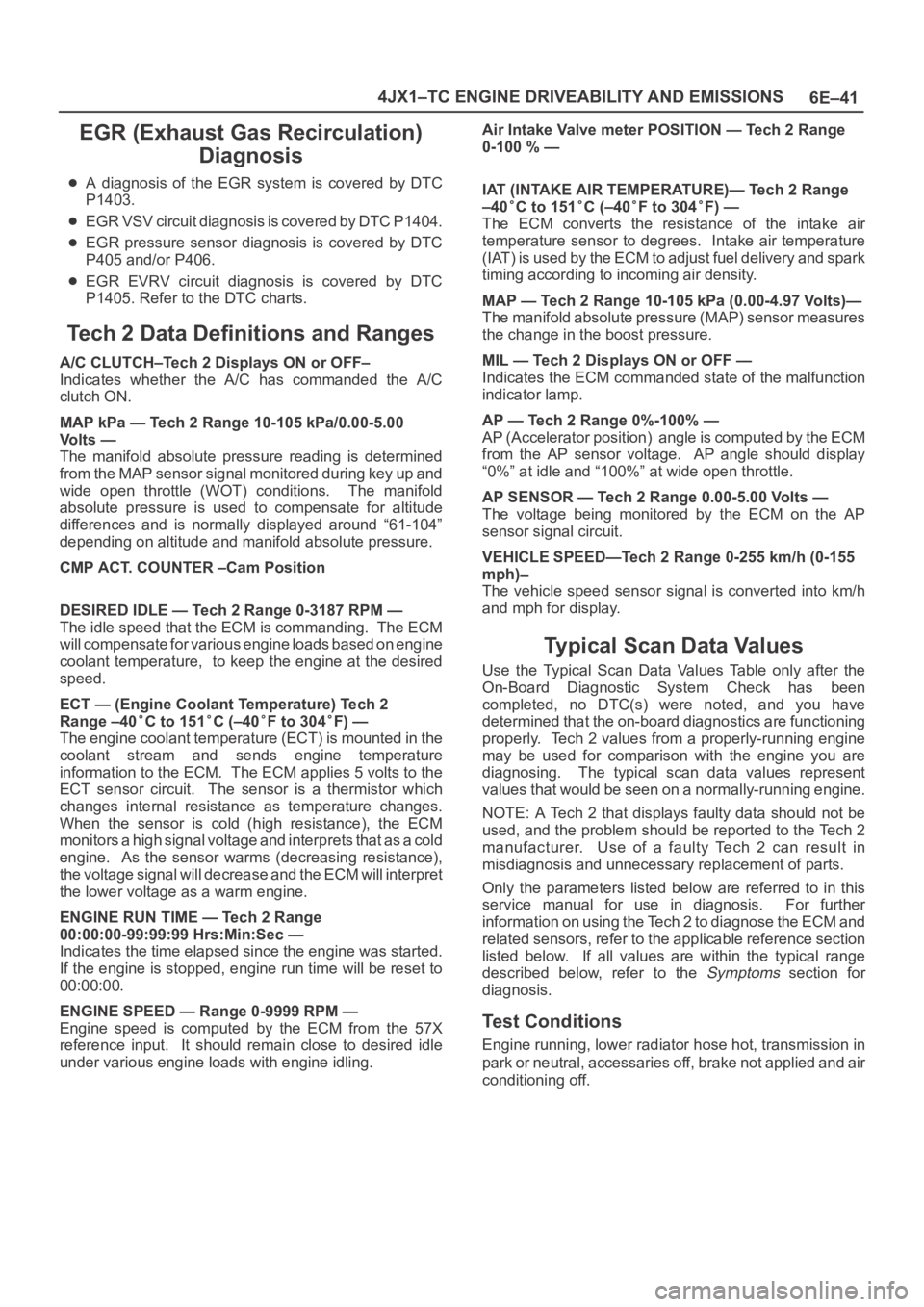
EGR (Exhaust Gas Recirculation)
Diagnosis
A diagnosis of the EGR system is covered by DTC
P1403.
EGR VSV circuit diagnosis is covered by DTC P1404.
EGR pressure sensor diagnosis is covered by DTC
P405 and/or P406.
EGR EVRV circuit diagnosis is covered by DTC
P1405. Refer to the DTC charts.
Tech 2 Data Definitions and Ranges
A/C CLUTCH–Tech 2 Displays ON or OFF–
Indicates whether the A/C has commanded the A/C
clutch ON.
MAP kPa — Tech 2 Range 10-105 kPa/0.00-5.00
Vo l t s —
The manifold absolute pressure reading is determined
from the MAP sensor signal monitored during key up and
wide open throttle (WOT) conditions. The manifold
absolute pressure is used to compensate for altitude
differences and is normally displayed around “61-104”
depending on altitude and manifold absolute pressure.
CMP ACT. COUNTER –Cam Position
DESIRED IDLE — Tech 2 Range 0-3187 RPM —
The idle speed that the ECM is commanding. The ECM
will compensate for various engine loads based on engine
coolant temperature, to keep the engine at the desired
speed.
ECT — (Engine Coolant Temperature) Tech 2
Range –40
C to 151C (–40F to 304F) —
The engine coolant temperature (ECT) is mounted in the
coolant stream and sends engine temperature
information to the ECM. The ECM applies 5 volts to the
ECT sensor circuit. The sensor is a thermistor which
changes internal resistance as temperature changes.
When the sensor is cold (high resistance), the ECM
monitors a high signal voltage and interprets that as a cold
engine. As the sensor warms (decreasing resistance),
the voltage signal will decrease and the ECM will interpret
the lower voltage as a warm engine.
ENGINE RUN TIME — Tech 2 Range
00:00:00-99:99:99 Hrs:Min:Sec —
Indicates the time elapsed since the engine was started.
If the engine is stopped, engine run time will be reset to
00:00:00.
ENGINE SPEED — Range 0-9999 RPM —
Engine speed is computed by the ECM from the 57X
reference input. It should remain close to desired idle
under various engine loads with engine idling.Air Intake Valve meter POSITION — Tech 2 Range
0-100 % —
IAT (INTAKE AIR TEMPERATURE)— Tech 2 Range
–40
C to 151C (–40F to 304F) —
The ECM converts the resistance of the intake air
temperature sensor to degrees. Intake air temperature
(IAT) is used by the ECM to adjust fuel delivery and spark
timing according to incoming air density.
MAP — Tech 2 Range 10-105 kPa (0.00-4.97 Volts)—
The manifold absolute pressure (MAP) sensor measures
the change in the boost pressure.
MIL — Tech 2 Displays ON or OFF —
Indicates the ECM commanded state of the malfunction
indicator lamp.
AP — Tech 2 Range 0%-100% —
AP (Accelerator position) angle is computed by the ECM
from the AP sensor voltage. AP angle should display
“0%” at idle and “100%” at wide open throttle.
AP SENSOR — Tech 2 Range 0.00-5.00 Volts —
The voltage being monitored by the ECM on the AP
sensor signal circuit.
VEHICLE SPEED—Tech 2 Range 0-255 km/h (0-155
mph)–
The vehicle speed sensor signal is converted into km/h
and mph for display.
Typical Scan Data Values
Use the Typical Scan Data Values Table only after the
On-Board Diagnostic System Check has been
completed, no DTC(s) were noted, and you have
determined that the on-board diagnostics are functioning
properly. Tech 2 values from a properly-running engine
may be used for comparison with the engine you are
diagnosing. The typical scan data values represent
values that would be seen on a normally-running engine.
NOTE: A Tech 2 that displays faulty data should not be
used, and the problem should be reported to the Tech 2
manufacturer. Use of a faulty Tech 2 can result in
misdiagnosis and unnecessary replacement of parts.
Only the parameters listed below are referred to in this
service manual for use in diagnosis. For further
information on using the Tech 2 to diagnose the ECM and
related sensors, refer to the applicable reference section
listed below. If all values are within the typical range
described below, refer to the
Symptoms section for
diagnosis.
Test Conditions
Engine running, lower radiator hose hot, transmission in
park or neutral, accessaries off, brake not applied and air
conditioning off.
Page 1943 of 6000
6E–50
4JX1–TC ENGINE DRIVEABILITY AND EMISSIONS
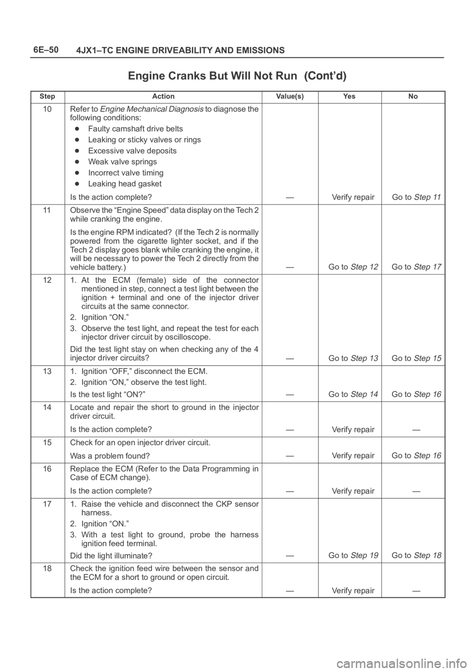
Engine Cranks But Will Not Run
StepNo Ye s Va l u e ( s ) Action
10Refer to Engine Mechanical Diagnosis to diagnose the
following conditions:
Faulty camshaft drive belts
Leaking or sticky valves or rings
Excessive valve deposits
Weak valve springs
Incorrect valve timing
Leaking head gasket
Is the action complete?
—Verify repairGo to Step 11
11Observe the “Engine Speed” data display on the Tech 2
while cranking the engine.
Is the engine RPM indicated? (If the Tech 2 is normally
powered from the cigarette lighter socket, and if the
Tech 2 display goes blank while cranking the engine, it
will be necessary to power the Tech 2 directly from the
vehicle battery.)
—Go to Step 12Go to Step 17
121. At the ECM (female) side of the connector
mentioned in step, connect a test light between the
ignition + terminal and one of the injector driver
circuits at the same connector.
2. Ignition “ON.”
3. Observe the test light, and repeat the test for each
injector driver circuit by oscilloscope.
Did the test light stay on when checking any of the 4
injector driver circuits?
—Go to Step 13Go to Step 15
131. Ignition “OFF,” disconnect the ECM.
2. Ignition “ON,” observe the test light.
Is the test light “ON?”
—Go to Step 14Go to Step 16
14Locate and repair the short to ground in the injector
driver circuit.
Is the action complete?
—Verify repair—
15Check for an open injector driver circuit.
Was a problem found?
—Verify repairGo to Step 16
16Replace the ECM (Refer to the Data Programming in
Case of ECM change).
Is the action complete?
—Verify repair—
171. Raise the vehicle and disconnect the CKP sensor
harness.
2. Ignition “ON.”
3. With a test light to ground, probe the harness
ignition feed terminal.
Did the light illuminate?
—Go to Step 19Go to Step 18
18Check the ignition feed wire between the sensor and
the ECM for a short to ground or open circuit.
Is the action complete?
—Verify repair—
Page 1945 of 6000
6E–52
4JX1–TC ENGINE DRIVEABILITY AND EMISSIONS
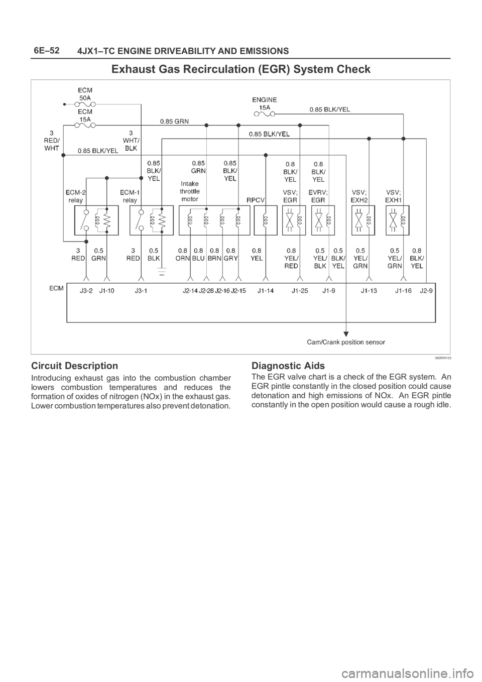
Exhaust Gas Recirculation (EGR) System Check
060RW135
Circuit Description
Introducing exhaust gas into the combustion chamber
lowers combustion temperatures and reduces the
formation of oxides of nitrogen (NOx) in the exhaust gas.
Lower combustion temperatures also prevent detonation.
Diagnostic Aids
The EGR valve chart is a check of the EGR system. An
EGR pintle constantly in the closed position could cause
detonation and high emissions of NOx. An EGR pintle
constantly in the open position would cause a rough idle.
Page 2071 of 6000
6E–178
4JX1–TC ENGINE DRIVEABILITY AND EMISSIONS
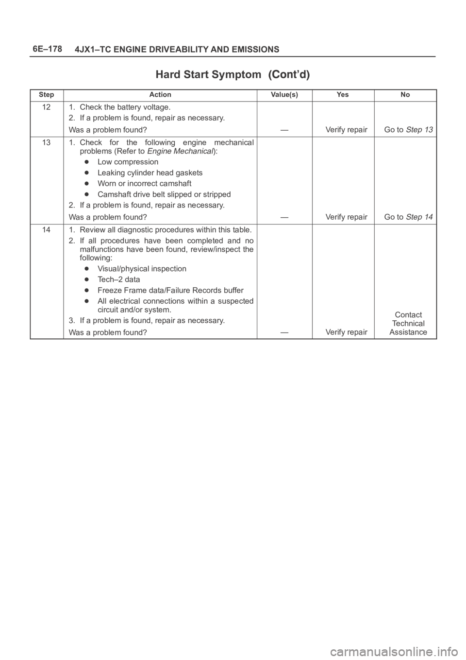
Hard Start Symptom
StepNo Ye s Va l u e ( s ) Action
121. Check the battery voltage.
2. If a problem is found, repair as necessary.
Was a problem found?
—Verify repairGo to Step 13
131. Check for the following engine mechanical
problems (Refer to
Engine Mechanical):
Low compression
Leaking cylinder head gaskets
Worn or incorrect camshaft
Camshaft drive belt slipped or stripped
2. If a problem is found, repair as necessary.
Was a problem found?
—Verify repairGo to Step 14
141. Review all diagnostic procedures within this table.
2. If all procedures have been completed and no
malfunctions have been found, review/inspect the
following:
Visual/physical inspection
Tech–2 data
Freeze Frame data/Failure Records buffer
All electrical connections within a suspected
circuit and/or system.
3. If a problem is found, repair as necessary.
Was a problem found?
—Verify repair
Contact
Te c h n i c a l
Assistance
Page 2088 of 6000
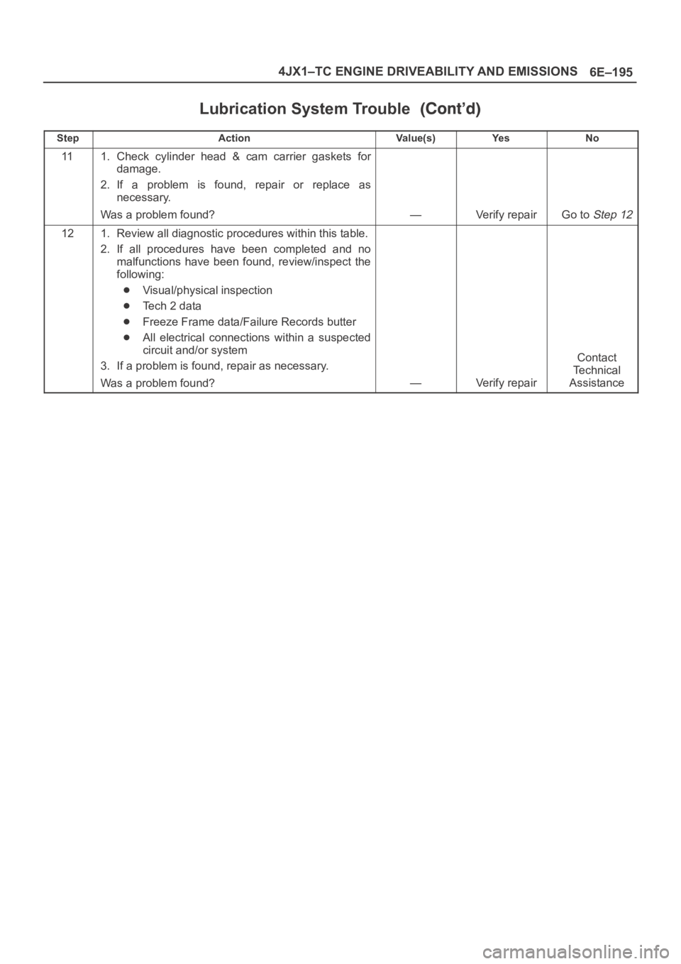
6E–195 4JX1–TC ENGINE DRIVEABILITY AND EMISSIONS
Lubrication System Trouble
StepNo Ye s Va l u e ( s ) Action
111. Check cylinder head & cam carrier gaskets for
damage.
2. If a problem is found, repair or replace as
necessary.
Was a problem found?
—Verify repairGo to Step 12
121. Review all diagnostic procedures within this table.
2. If all procedures have been completed and no
malfunctions have been found, review/inspect the
following:
Visual/physical inspection
Te c h 2 d a t a
Freeze Frame data/Failure Records butter
All electrical connections within a suspected
circuit and/or system
3. If a problem is found, repair as necessary.
Was a problem found?
—Verify repair
Contact
Te c h n i c a l
Assistance
Page 2090 of 6000
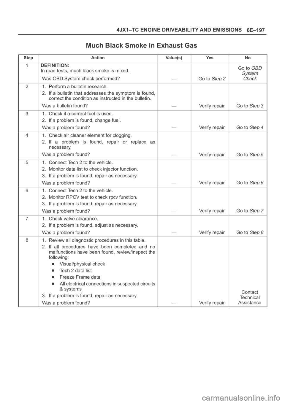
6E–197 4JX1–TC ENGINE DRIVEABILITY AND EMISSIONS
Much Black Smoke in Exhaust Gas
StepActionVa l u e ( s )Ye sNo
1DEFINITION:
In road tests, much black smoke is mixed.
Was OBD System check performed?
—Go to Step 2
Go to OBD
System
Check
21. Perform a bulletin research.
2. If a bulletin that addresses the symptom is found,
correct the condition as instructed in the bulletin.
Was a bulletin found?
—Verify repairGo to Step 3
31. Check if a correct fuel is used.
2. If a problem is found, change fuel.
Was a problem found?
—Verify repairGo to Step 4
41. Check air cleaner element for clogging.
2. If a problem is found, repair or replace as
necessary.
Was a problem found?
—Verify repairGo to Step 5
51. Connect Tech 2 to the vehicle.
2. Monitor data list to check injector function.
3. If a problem is found, repair as necessary.
Was a problem found?
—Verify repairGo to Step 6
61. Connect Tech 2 to the vehicle.
2. Monitor RPCV test to check rpcv function.
3. If a problem is found, repair as necessary.
Was a problem found?
—Verify repairGo to Step 7
71. Check valve clearance.
2. If a problem is found, adjust as necessary.
Was a problem found?
—Verify repairGo to Step 8
81. Review all diagnostic procedures in this table.
2. If all procedures have been completed and no
malfunctions have been found, review/inspect the
following:
Visual/physical check
Tech 2 data list
Freeze Frame data
All electrical connections in suspected circuits
& systems
3. If a problem is found, repair as necessary.
Was a problem found?
—Verify repair
Contact
Te c h n i c a l
Assistance
Page 2091 of 6000
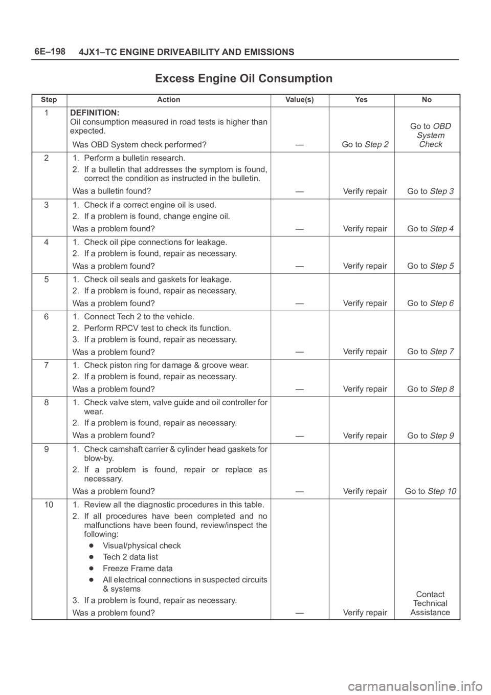
6E–198
4JX1–TC ENGINE DRIVEABILITY AND EMISSIONS
Excess Engine Oil Consumption
StepActionVa l u e ( s )Ye sNo
1DEFINITION:
Oil consumption measured in road tests is higher than
expected.
Was OBD System check performed?
—Go to Step 2
Go to OBD
System
Check
21. Perform a bulletin research.
2. If a bulletin that addresses the symptom is found,
correct the condition as instructed in the bulletin.
Was a bulletin found?
—Verify repairGo to Step 3
31. Check if a correct engine oil is used.
2. If a problem is found, change engine oil.
Was a problem found?
—Verify repairGo to Step 4
41. Check oil pipe connections for leakage.
2. If a problem is found, repair as necessary.
Was a problem found?
—Verify repairGo to Step 5
51. Check oil seals and gaskets for leakage.
2. If a problem is found, repair as necessary.
Was a problem found?
—Verify repairGo to Step 6
61. Connect Tech 2 to the vehicle.
2. Perform RPCV test to check its function.
3. If a problem is found, repair as necessary.
Was a problem found?
—Verify repairGo to Step 7
71. Check piston ring for damage & groove wear.
2. If a problem is found, repair as necessary.
Was a problem found?
—Verify repairGo to Step 8
81. Check valve stem, valve guide and oil controller for
wear.
2. If a problem is found, repair as necessary.
Was a problem found?
—Verify repairGo to Step 9
91. Check camshaft carrier & cylinder head gaskets for
blow-by.
2. If a problem is found, repair or replace as
necessary.
Was a problem found?
—Verify repairGo to Step 10
101. Review all the diagnostic procedures in this table.
2. If all procedures have been completed and no
malfunctions have been found, review/inspect the
following:
Visual/physical check
Tech 2 data list
Freeze Frame data
All electrical connections in suspected circuits
& systems
3. If a problem is found, repair as necessary.
Was a problem found?
—Verify repair
Contact
Te c h n i c a l
Assistance
Page 2107 of 6000
6E–214
4JX1–TC ENGINE DRIVEABILITY AND EMISSIONS
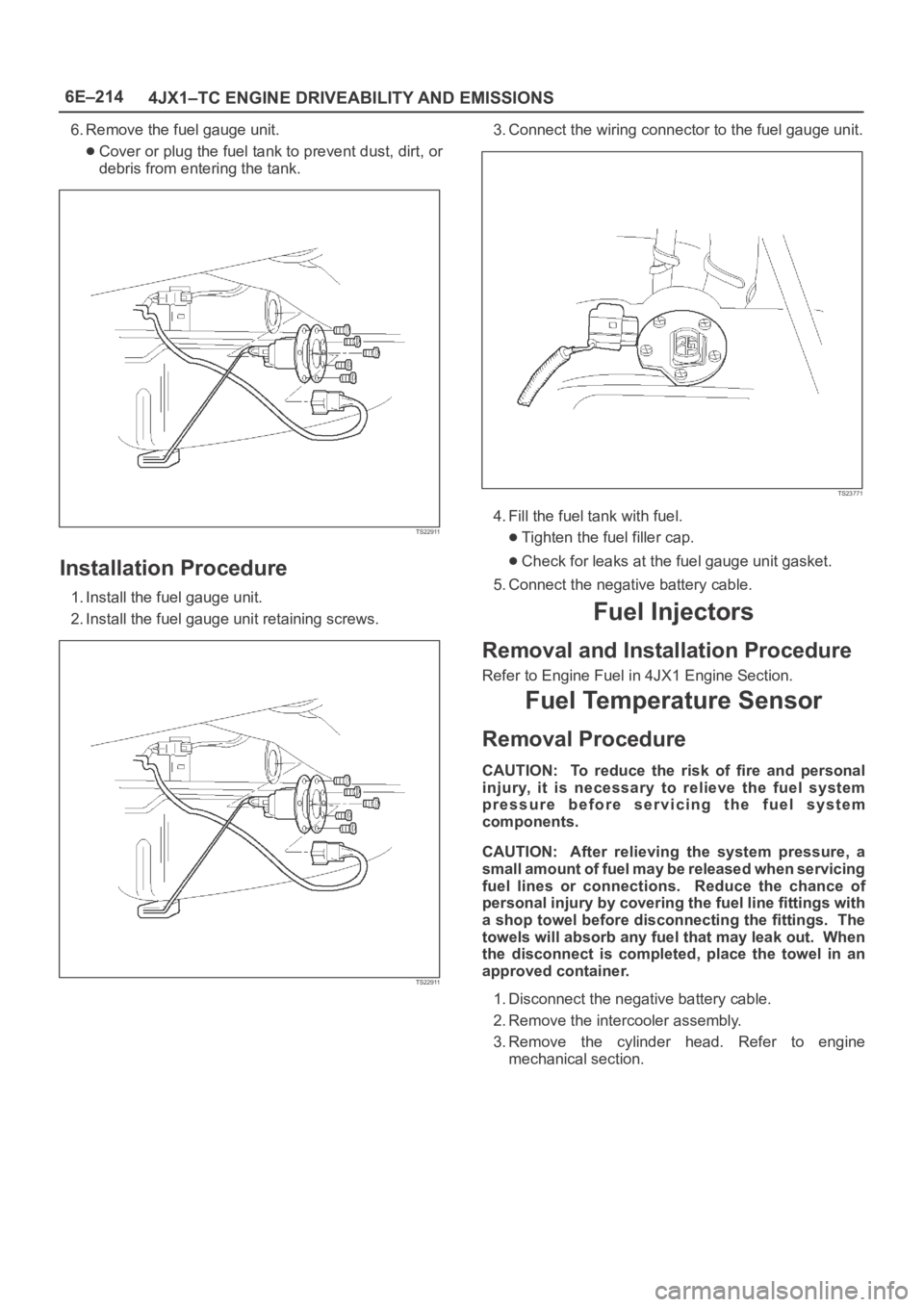
6. Remove the fuel gauge unit.
Cover or plug the fuel tank to prevent dust, dirt, or
debris from entering the tank.
TS22911
Installation Procedure
1. Install the fuel gauge unit.
2. Install the fuel gauge unit retaining screws.
TS22911
3. Connect the wiring connector to the fuel gauge unit.
TS23771
4. Fill the fuel tank with fuel.
Tighten the fuel filler cap.
Check for leaks at the fuel gauge unit gasket.
5. Connect the negative battery cable.
Fuel Injectors
Removal and Installation Procedure
Refer to Engine Fuel in 4JX1 Engine Section.
Fuel Temperature Sensor
Removal Procedure
CAUTION: To reduce the risk of fire and personal
injury, it is necessary to relieve the fuel system
pressure before servicing the fuel system
components.
CAUTION: After relieving the system pressure, a
small amount of fuel may be released when servicing
fuel lines or connections. Reduce the chance of
personal injury by covering the fuel line fittings with
a shop towel before disconnecting the fittings. The
towels will absorb any fuel that may leak out. When
the disconnect is completed, place the towel in an
approved container.
1. Disconnect the negative battery cable.
2. Remove the intercooler assembly.
3. Remove the cylinder head. Refer to engine
mechanical section.