1998 OPEL FRONTERA ECU
[x] Cancel search: ECUPage 2304 of 6000
TRANSMISSION CONTROL SYSTEM (4L30–E)7A1–59
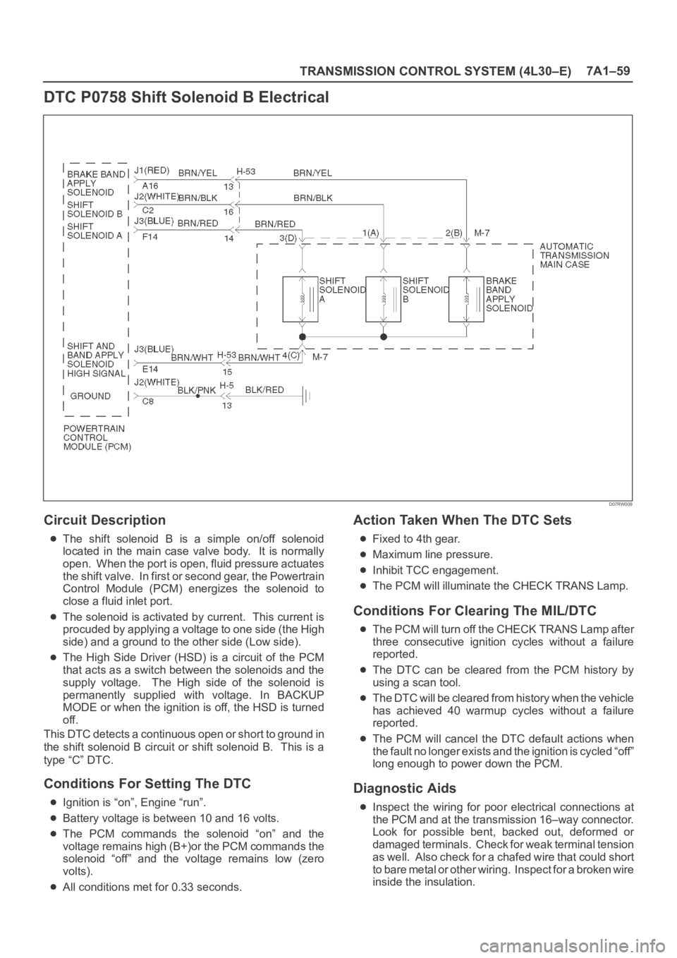
DTC P0758 Shift Solenoid B Electrical
D07RW009
Circuit Description
The shift solenoid B is a simple on/off solenoid
located in the main case valve body. It is normally
open. When the port is open, fluid pressure actuates
the shift valve. In first or second gear, the Powertrain
Control Module (PCM) energizes the solenoid to
close a fluid inlet port.
The solenoid is activated by current. This current is
procuded by applying a voltage to one side (the High
side) and a ground to the other side (Low side).
The High Side Driver (HSD) is a circuit of the PCM
that acts as a switch between the solenoids and the
supply voltage. The High side of the solenoid is
permanently supplied with voltage. In BACKUP
MODE or when the ignition is off, the HSD is turned
off.
This DTC detects a continuous open or short to ground in
the shift solenoid B circuit or shift solenoid B. This is a
type “C” DTC.
Conditions For Setting The DTC
Ignition is “on”, Engine “run”.
Battery voltage is between 10 and 16 volts.
The PCM commands the solenoid “on” and the
voltage remains high (B+)or the PCM commands the
solenoid “off” and the voltage remains low (zero
volts).
All conditions met for 0.33 seconds.
Action Taken When The DTC Sets
Fixed to 4th gear.
Maximum line pressure.
Inhibit TCC engagement.
The PCM will illuminate the CHECK TRANS Lamp.
Conditions For Clearing The MIL/DTC
The PCM will turn off the CHECK TRANS Lamp after
three consecutive ignition cycles without a failure
reported.
The DTC can be cleared from the PCM history by
using a scan tool.
The DTC will be cleared from history when the vehicle
has achieved 40 warmup cycles without a failure
reported.
The PCM will cancel the DTC default actions when
the fault no longer exists and the ignition is cycled “off”
long enough to power down the PCM.
Diagnostic Aids
Inspect the wiring for poor electrical connections at
the PCM and at the transmission 16–way connector.
Look for possible bent, backed out, deformed or
damaged terminals. Check for weak terminal tension
as we ll. A lso ch eck fo r a ch af e d w ire th at cou l d s ho r t
to bare metal or other wiring. Inspect for a broken wire
inside the insulation.
Page 2308 of 6000
TRANSMISSION CONTROL SYSTEM (4L30–E)7A1–63
DTC P1790 ROM Transmission Side
Bad Check Sum
Circuit Description
Transmission Side Read Only Memory (ROM) and
Electronically Erasable Programmable Read Only
Memory (EEPROM) is an electronic circuit that controls
the transmission control in the Powertrain Control Module
(PCM).
This DTC detects a check sum error. This is a type “C”
DTC.
Conditions For Setting The DTC
Detects check sum error for 1 second.
Action Taken When The DTC Sets
Maximum line pressure.
Immediate landing to 4th gear.
Inhibit TCC engagement.
The PCM will illuminate the CHECK TRANS Lamp.
Conditions For Clearing The MIL/DTC
The PCM will turn off the CHECK TRANS Lamp after
three consecutive ignition cycles without a failure
reported.
The DTC can be cleared from the PCM history by
using a scan tool.
The DTC will be cleared from history when the vehicle
has achieved 40 warmup cycles without a failure
reported.
The PCM will cancel the DTC default actions when
the fault no longer exists and the ignition is cycled “off”
long enough to power down the PCM.
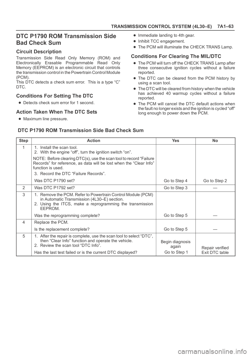
DTC P1790 ROM Transmission Side Bad Check Sum
StepActionYe sNo
11. Install the scan tool.
2. With the engine “off”, turn the ignition switch “on”.
NOTE: Before clearing DTC(s), use the scan tool to record “Failure
Records” for reference, as data will be lost when the “Clear Info”
function is used.
3. Record the DTC “Failure Records”.
Was DTC P1790 set?
Go to Step 4Go to Step 2
2Was DTC P1792 set?Go to Step 3—
31. Remove the PCM. Refer to Powertrain Control Module (PCM)
in Automatic Transmission (4L30–E) section.
2. Using the ITCS, make a reprogramming the transmission
EEPROM.
Was the reprogramming complete?
Go to Step 5—
4Replace the PCM.
Is the replacement complete?
Go to Step 5—
51. After the repair is complete, use the scan tool to select “DTC”,
then “Clear Info” function and operate the vehicle.
2. Review the scan tool “DTC Info”.
Has the last test failed or is the current DTC displayed?
Begin diagnosis
again
Go to Step 1
Repair verified
Exit DTC table
Page 2309 of 6000
7A1–64
TRANSMISSION CONTROL SYSTEM (4L30–E)
DTC P1792 EEPROM Transmission
Side Bad Check Sum
Circuit Description
Transmission Side Read Only Memory (ROM) and
Electronically Erasable Programmable Read Only
Memory (EEPROM) is an electronic circuit that controls
the transmission control in the Powertrain Control Module
(PCM).
This DTC detects a check sum error. This is a type “C”
DTC.
Conditions For Setting The DTC
Detects check sum error for 1 second.
Action Taken When The DTC Sets
Maximum line pressure.
Immediate landing to 4th gear.
Inhibit TCC engagement.
The PCM will illuminate the CHECK TRANS Lamp.
Conditions For Clearing The MIL/DTC
The PCM will turn off the CHECK TRANS Lamp after
three consecutive ignition cycles without a failure
reported.
The DTC can be cleared from the PCM history by
using a scan tool.
The DTC will be cleared from history when the vehicle
has achieved 40 warmup cycles without a failure
reported.
The PCM will cancel the DTC default actions when
the fault no longer exists and the ignition is cycled “off”
long enough to power down the PCM.
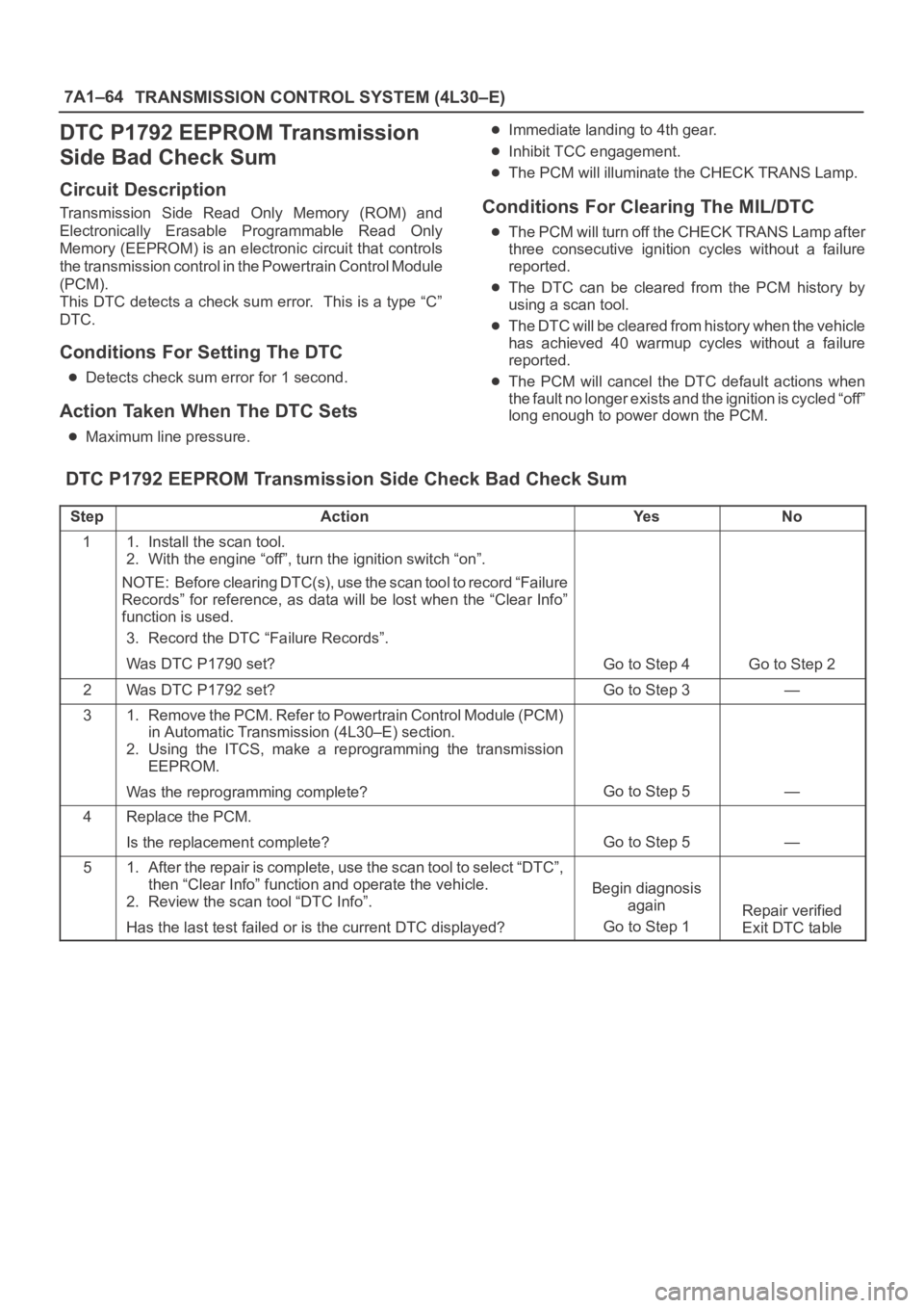
DTC P1792 EEPROM Transmission Side Check Bad Check Sum
StepActionYe sNo
11. Install the scan tool.
2. With the engine “off”, turn the ignition switch “on”.
NOTE: Before clearing DTC(s), use the scan tool to record “Failure
Records” for reference, as data will be lost when the “Clear Info”
function is used.
3. Record the DTC “Failure Records”.
Was DTC P1790 set?
Go to Step 4Go to Step 2
2Was DTC P1792 set?Go to Step 3—
31. Remove the PCM. Refer to Powertrain Control Module (PCM)
in Automatic Transmission (4L30–E) section.
2. Using the ITCS, make a reprogramming the transmission
EEPROM.
Was the reprogramming complete?
Go to Step 5—
4Replace the PCM.
Is the replacement complete?
Go to Step 5—
51. After the repair is complete, use the scan tool to select “DTC”,
then “Clear Info” function and operate the vehicle.
2. Review the scan tool “DTC Info”.
Has the last test failed or is the current DTC displayed?
Begin diagnosis
again
Go to Step 1
Repair verified
Exit DTC table
Page 2331 of 6000
MANUAL TRANSMISSION7B–13
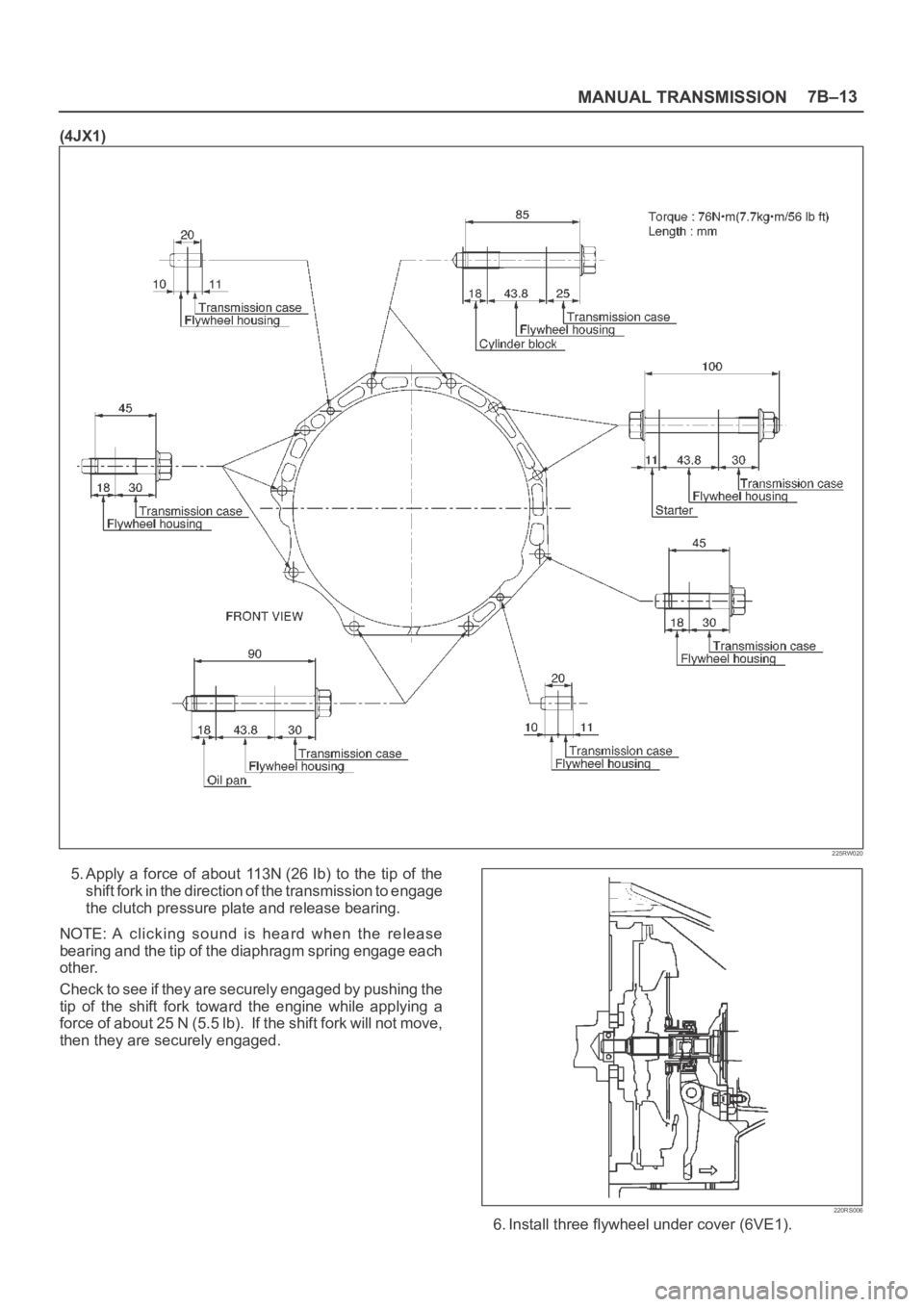
(4JX1)
225RW020
5. Apply a force of about 113N (26 Ib) to the tip of the
shift fork in the direction of the transmission to engage
the clutch pressure plate and release bearing.
NOTE: A clicking sound is heard when the release
bearing and the tip of the diaphragm spring engage each
other.
Check to see if they are securely engaged by pushing the
tip of the shift fork toward the engine while applying a
force of about 25 N (5.5 lb). If the shift fork will not move,
then they are securely engaged.
220RS006
6. Install three flywheel under cover (6VE1).
Page 2540 of 6000
LIGHTING SYSTEM8A–1
BODY AND ACCESSORIES
CONTENTS
Lighting System 8A. . . . . . . . . . . . . . . . . . . . . . . . .
Wiper/Washer System 8B. . . . . . . . . . . . . . . . . . .
Entertainment 8C. . . . . . . . . . . . . . . . . . . . . . . . . . .
Wiring System 8D. . . . . . . . . . . . . . . . . . . . . . . . . .
Meter and Gauge 8E. . . . . . . . . . . . . . . . . . . . . . . Body Structure 8F. . . . . . . . . . . . . . . . . . . . . . . . . .
Seats 8G. . . . . . . . . . . . . . . . . . . . . . . . . . . . . . . . . .
Security and Locks 8H. . . . . . . . . . . . . . . . . . . . . .
Sun Roof/Convertible Top 8I. . . . . . . . . . . . . . . .
Exterior/Interior Trim 8J. . . . . . . . . . . . . . . . . . . . .
LIGHTING SYSTEM
CONTENTS
Service Precaution 8A–2. . . . . . . . . . . . . . . . . . . . . .
Headlight Bulb 8A–3. . . . . . . . . . . . . . . . . . . . . . . . . .
Removal 8A–3. . . . . . . . . . . . . . . . . . . . . . . . . . . . .
Installation 8A–3. . . . . . . . . . . . . . . . . . . . . . . . . . . .
Headlight 8A–4. . . . . . . . . . . . . . . . . . . . . . . . . . . . . . .
Headlight and Associated Parts 8A–4. . . . . . . . .
Removal 8A–4. . . . . . . . . . . . . . . . . . . . . . . . . . . . .
Installation 8A–4. . . . . . . . . . . . . . . . . . . . . . . . . . . .
Headlight Adjustment 8A–4. . . . . . . . . . . . . . . . . .
Fog Light Bulb 8A–5. . . . . . . . . . . . . . . . . . . . . . . . . .
Removal 8A–5. . . . . . . . . . . . . . . . . . . . . . . . . . . . .
Installation 8A–5. . . . . . . . . . . . . . . . . . . . . . . . . . . .
Fog Light Assembly 8A–6. . . . . . . . . . . . . . . . . . . . .
Removal 8A–6. . . . . . . . . . . . . . . . . . . . . . . . . . . . .
Installation 8A–6. . . . . . . . . . . . . . . . . . . . . . . . . . . .
Fog Light Adjustment 8A–6. . . . . . . . . . . . . . . . . .
Clarence Light Bulb 8A–6. . . . . . . . . . . . . . . . . . . . . .
Removal 8A–6. . . . . . . . . . . . . . . . . . . . . . . . . . . . .
Installation 8A–6. . . . . . . . . . . . . . . . . . . . . . . . . . . .
Rear Fog Light Bulb (RHD) 8A–7. . . . . . . . . . . . . . .
Removal 8A–7. . . . . . . . . . . . . . . . . . . . . . . . . . . . .
Installation 8A–7. . . . . . . . . . . . . . . . . . . . . . . . . . . .
Taillight Bulb (Body) 8A–7. . . . . . . . . . . . . . . . . . . . .
Removal 8A–7. . . . . . . . . . . . . . . . . . . . . . . . . . . . .
Installation 8A–7. . . . . . . . . . . . . . . . . . . . . . . . . . . .
Taillight Bulb (Bumper) 8A–8. . . . . . . . . . . . . . . . . . .
Removal 8A–8. . . . . . . . . . . . . . . . . . . . . . . . . . . . .
Installation 8A–8. . . . . . . . . . . . . . . . . . . . . . . . . . . .
License Plate Light Bulb (Body) 8A–8. . . . . . . . . . .
Removal 8A–8. . . . . . . . . . . . . . . . . . . . . . . . . . . . .
Installation 8A–8. . . . . . . . . . . . . . . . . . . . . . . . . . . .
License Plate Light Bulb (Bumper) 8A–9. . . . . . . . .
Removal 8A–9. . . . . . . . . . . . . . . . . . . . . . . . . . . . .
Installation 8A–9. . . . . . . . . . . . . . . . . . . . . . . . . . . .
Stoplight Bulb 8A–9. . . . . . . . . . . . . . . . . . . . . . . . . . .
Removal and Installation 8A–9. . . . . . . . . . . . . . . High Mount Stoplight 8A–10. . . . . . . . . . . . . . . . . . . .
Removal 8A–10. . . . . . . . . . . . . . . . . . . . . . . . . . . . .
Installation 8A–10. . . . . . . . . . . . . . . . . . . . . . . . . . . .
Front Turn Signal Light Bulb 8A–10. . . . . . . . . . . . . .
Removal 8A–10. . . . . . . . . . . . . . . . . . . . . . . . . . . . .
Installation 8A–10. . . . . . . . . . . . . . . . . . . . . . . . . . . .
Side Turn Signal Light Bulb 8A–11. . . . . . . . . . . . . . .
Removal 8A–11. . . . . . . . . . . . . . . . . . . . . . . . . . . . .
Installation 8A–11. . . . . . . . . . . . . . . . . . . . . . . . . . . .
Rear Turn Signal Light Bulb 8A–11. . . . . . . . . . . . . .
Removal 8A–11. . . . . . . . . . . . . . . . . . . . . . . . . . . . .
Installation 8A–11. . . . . . . . . . . . . . . . . . . . . . . . . . .
Backup Light Bulb 8A–12. . . . . . . . . . . . . . . . . . . . . . .
Removal 8A–12. . . . . . . . . . . . . . . . . . . . . . . . . . . . .
Installation 8A–12
. . . . . . . . . . . . . . . . . . . . . . . . . . .
Dome Light Bulb 8A–12. . . . . . . . . . . . . . . . . . . . . . . .
Removal 8A–12. . . . . . . . . . . . . . . . . . . . . . . . . . . . .
Installation 8A–12. . . . . . . . . . . . . . . . . . . . . . . . . . . .
Luggage Room Light Bulb 8A–13. . . . . . . . . . . . . . . .
Removal 8A–13. . . . . . . . . . . . . . . . . . . . . . . . . . . . .
Installation 8A–13. . . . . . . . . . . . . . . . . . . . . . . . . . . .
Courtesy Light Bulb 8A–13. . . . . . . . . . . . . . . . . . . . . .
Removal 8A–13. . . . . . . . . . . . . . . . . . . . . . . . . . . . .
Installation 8A–13. . . . . . . . . . . . . . . . . . . . . . . . . . . .
Map Light Switch/Bulb 8A–14. . . . . . . . . . . . . . . . . . .
Removal 8A–14. . . . . . . . . . . . . . . . . . . . . . . . . . . . .
Installation 8A–14. . . . . . . . . . . . . . . . . . . . . . . . . . . .
Cigarette Lighter Illumination Bulb 8A–14. . . . . . . . .
Removal 8A–14. . . . . . . . . . . . . . . . . . . . . . . . . . . . .
Installation 8A–14. . . . . . . . . . . . . . . . . . . . . . . . . . .
Ashtray Illumination Bulb 8A–15. . . . . . . . . . . . . . . . .
Removal 8A–15. . . . . . . . . . . . . . . . . . . . . . . . . . . . .
Installation 8A–15. . . . . . . . . . . . . . . . . . . . . . . . . . . .
Glove Box Illumination Bulb 8A–15. . . . . . . . . . . . . . .
Removal 8A–15. . . . . . . . . . . . . . . . . . . . . . . . . . . . .
Installation 8A–15. . . . . . . . . . . . . . . . . . . . . . . . . . . .
Page 2558 of 6000
LIGHTING SYSTEM8A–19
Fog Light Switch
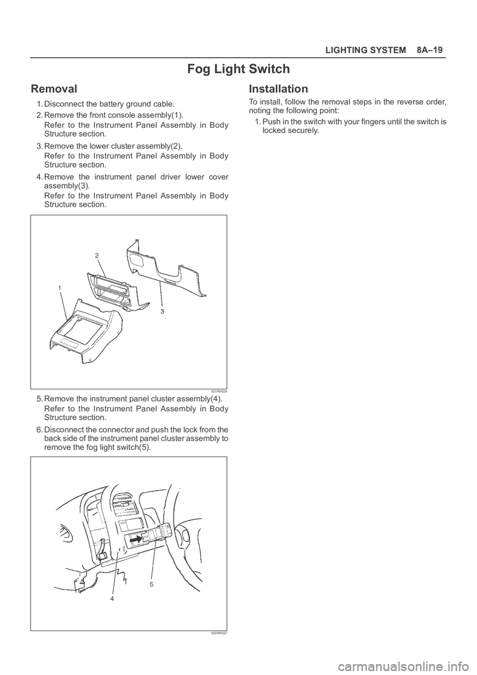
Removal
1. Disconnect the battery ground cable.
2. Remove the front console assembly(1).
Refer to the Instrument Panel Assembly in Body
Structure section.
3. Remove the lower cluster assembly(2).
Refer to the Instrument Panel Assembly in Body
Structure section.
4. Remove the instrument panel driver lower cover
assembly(3).
Refer to the Instrument Panel Assembly in Body
Structure section.
821RW024
5. Remove the instrument panel cluster assembly(4).
Refer to the Instrument Panel Assembly in Body
Structure section.
6. Disconnect the connector and push the lock from the
back side of the instrument panel cluster assembly to
remove the fog light switch(5).
825RW027
Installation
To install, follow the removal steps in the reverse order,
noting the following point:
1. Push in the switch with your fingers until the switch is
locked securely.
Page 2561 of 6000
8A–22LIGHTING SYSTEM
Hazard Warning Switch
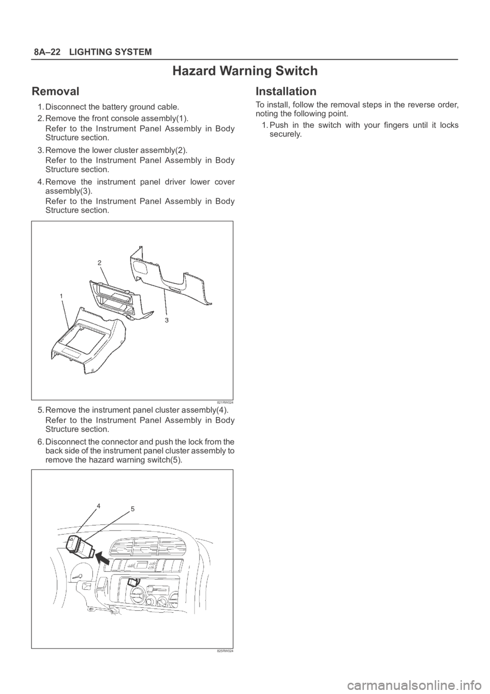
Removal
1. Disconnect the battery ground cable.
2. Remove the front console assembly(1).
Refer to the Instrument Panel Assembly in Body
Structure section.
3. Remove the lower cluster assembly(2).
Refer to the Instrument Panel Assembly in Body
Structure section.
4. Remove the instrument panel driver lower cover
assembly(3).
Refer to the Instrument Panel Assembly in Body
Structure section.
821RW024
5. Remove the instrument panel cluster assembly(4).
Refer to the Instrument Panel Assembly in Body
Structure section.
6. Disconnect the connector and push the lock from the
back side of the instrument panel cluster assembly to
remove the hazard warning switch(5).
825RW024
Installation
To install, follow the removal steps in the reverse order,
noting the following point.
1. Push in the switch with your fingers until it locks
securely.
Page 2563 of 6000
8A–24LIGHTING SYSTEM
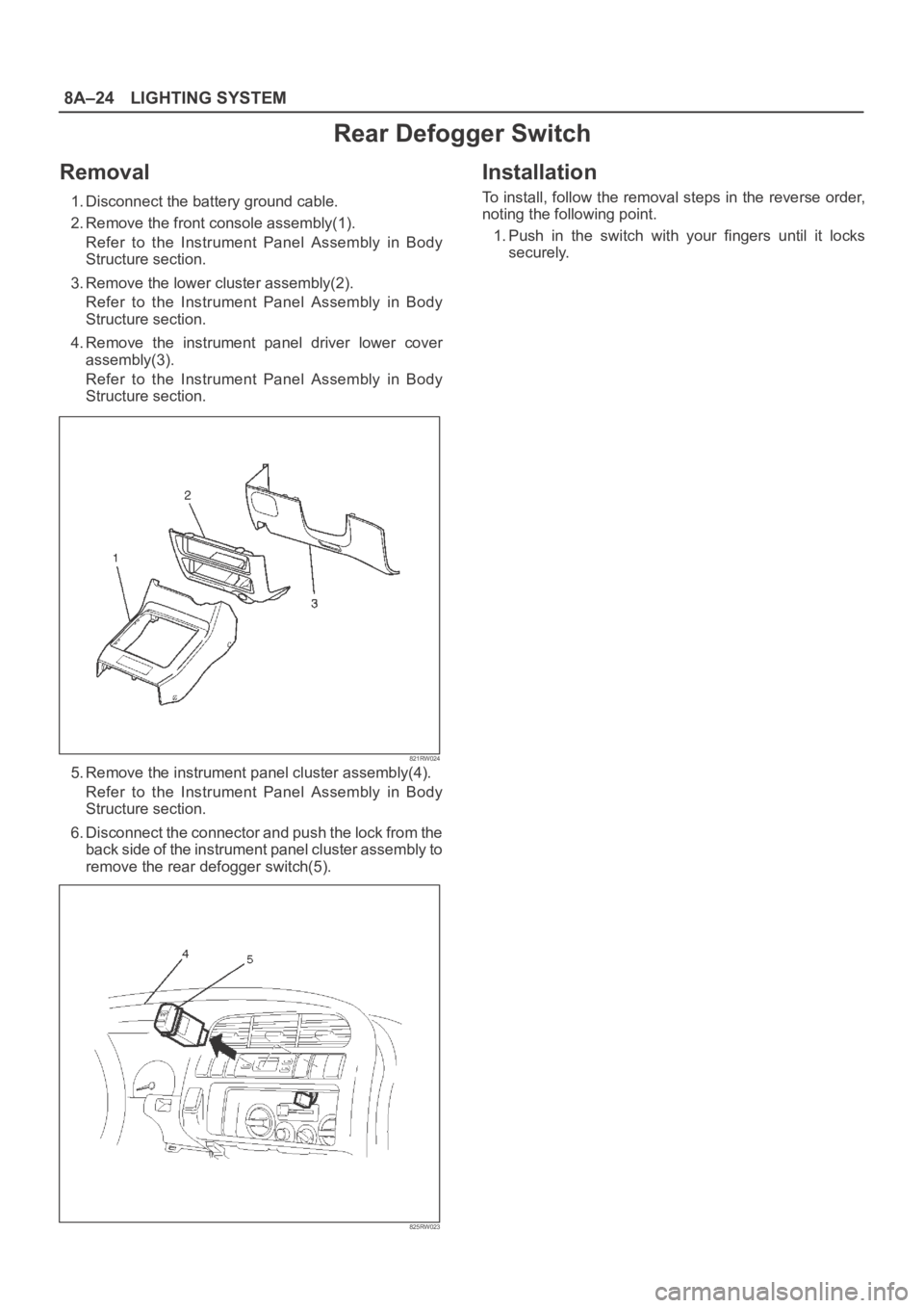
Rear Defogger Switch
Removal
1. Disconnect the battery ground cable.
2. Remove the front console assembly(1).
Refer to the Instrument Panel Assembly in Body
Structure section.
3. Remove the lower cluster assembly(2).
Refer to the Instrument Panel Assembly in Body
Structure section.
4. Remove the instrument panel driver lower cover
assembly(3).
Refer to the Instrument Panel Assembly in Body
Structure section.
821RW024
5. Remove the instrument panel cluster assembly(4).
Refer to the Instrument Panel Assembly in Body
Structure section.
6. Disconnect the connector and push the lock from the
back side of the instrument panel cluster assembly to
remove the rear defogger switch(5).
825RW023
Installation
To install, follow the removal steps in the reverse order,
noting the following point.
1. Push in the switch with your fingers until it locks
securely.