1998 OPEL FRONTERA ECU
[x] Cancel search: ECUPage 1924 of 6000
6E–31 4JX1–TC ENGINE DRIVEABILITY AND EMISSIONS
060RW120
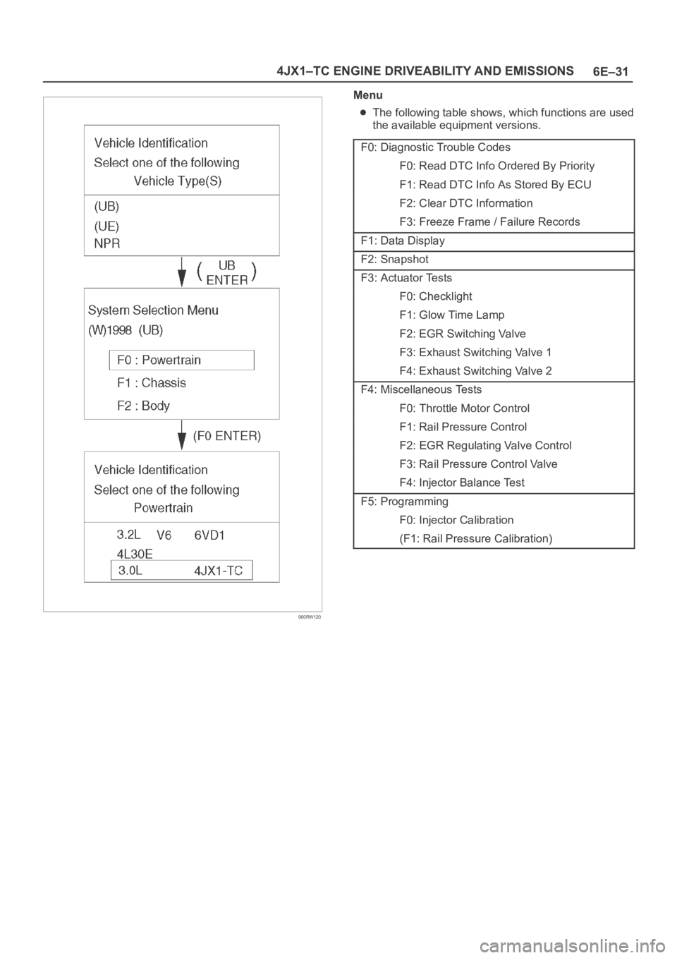
Menu
The following table shows, which functions are used
the available equipment versions.
F0: Diagnostic Trouble Codes
F0: Read DTC Info Ordered By Priority
F1: Read DTC Info As Stored By ECU
F2: Clear DTC Information
F3: Freeze Frame / Failure Records
F1: Data Display
F2: Snapshot
F3: Actuator Tests
F0: Checklight
F1: Glow Time Lamp
F2: EGR Switching Valve
F3: Exhaust Switching Valve 1
F4: Exhaust Switching Valve 2
F4: Miscellaneous Tests
F0: Throttle Motor Control
F1: Rail Pressure Control
F2: EGR Regulating Valve Control
F3: Rail Pressure Control Valve
F4: Injector Balance Test
F5: Programming
F0: Injector Calibration
(F1: Rail Pressure Calibration)
Page 1926 of 6000
6E–33 4JX1–TC ENGINE DRIVEABILITY AND EMISSIONS
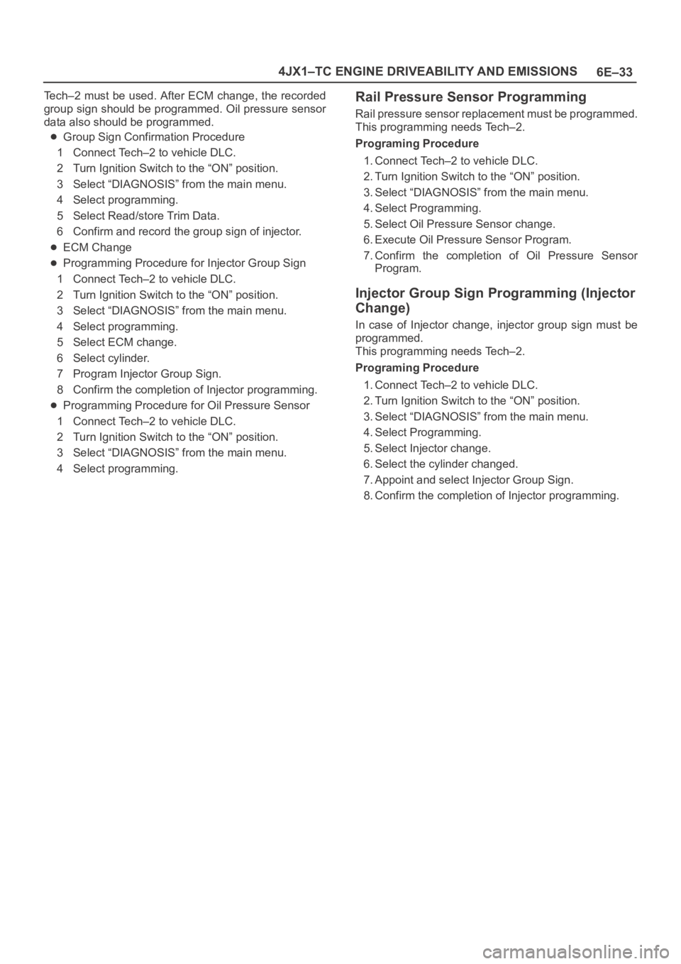
Tech–2 must be used. After ECM change, the recorded
group sign should be programmed. Oil pressure sensor
data also should be programmed.
Group Sign Confirmation Procedure
1 Connect Tech–2 to vehicle DLC.
2 Turn Ignition Switch to the “ON” position.
3 Select “DIAGNOSIS” from the main menu.
4 Select programming.
5 Select Read/store Trim Data.
6 Confirm and record the group sign of injector.
ECM Change
Programming Procedure for Injector Group Sign
1 Connect Tech–2 to vehicle DLC.
2 Turn Ignition Switch to the “ON” position.
3 Select “DIAGNOSIS” from the main menu.
4 Select programming.
5 Select ECM change.
6 Select cylinder.
7 Program Injector Group Sign.
8 Confirm the completion of Injector programming.
Programming Procedure for Oil Pressure Sensor
1 Connect Tech–2 to vehicle DLC.
2 Turn Ignition Switch to the “ON” position.
3 Select “DIAGNOSIS” from the main menu.
4 Select programming.
Rail Pressure Sensor Programming
Rail pressure sensor replacement must be programmed.
This programming needs Tech–2.
Programing Procedure
1. Connect Tech–2 to vehicle DLC.
2. Turn Ignition Switch to the “ON” position.
3. Select “DIAGNOSIS” from the main menu.
4. Select Programming.
5. Select Oil Pressure Sensor change.
6. Execute Oil Pressure Sensor Program.
7. Confirm the completion of Oil Pressure Sensor
Program.
Injector Group Sign Programming (Injector
Change)
In case of Injector change, injector group sign must be
programmed.
This programming needs Tech–2.
Programing Procedure
1. Connect Tech–2 to vehicle DLC.
2. Turn Ignition Switch to the “ON” position.
3. Select “DIAGNOSIS” from the main menu.
4. Select Programming.
5. Select Injector change.
6. Select the cylinder changed.
7. Appoint and select Injector Group Sign.
8. Confirm the completion of Injector programming.
Page 1932 of 6000
6E–39 4JX1–TC ENGINE DRIVEABILITY AND EMISSIONS
Engine Control Module ECM
Diagnosis
To read and clear diagnostic trouble codes, use a Tech 2.
IMPORTANT:Use of a Tech 2 is recommended to clear
diagnostic trouble codes from the ECM memory.
Diagnostic trouble codes can also be cleared by turning
the ignition “OFF” and disconnecting the battery power
from the ECM for 30 seconds. Turning off the ignition and
disconnecting the battery power from the ECM will cause
all diagnostic information in the ECM memory to be
cleared. Therefore, all the diagnostic tests will have to be
re-run.
Since the ECM can have a failure which may affect only
one circuit, following the diagnostic procedures in this
section will determine which circuit has a problem and
where it is.
If a diagnostic chart indicates that the ECM connections
or the ECM is the cause of a problem, and the ECM is
replaced, but this does not correct the problem, one of the
following may be the reason:
There is a problem with the ECM terminal
connections. The terminals may have to be removed
from the connector in order to check them properly.
The problem is intermittent. This means that the
problem is not present at the time the system is being
checked. In this case, refer to the
Symptoms portion
of the manual and make a careful physical inspection
of all components and wiring associated with the
affected system.
There is a shorted solenoid, relay coil, or harness.
Solenoids and relays are turned “ON” and “OFF” by
the ECM using internal electronic switches called
drivers. A shorted solenoid, relay coil, or harness will
not damage the ECM but will cause the solenoid or
relay to be inoperative.
Multiple ECM Information Sensor
DTCS Set
Circuit Description
The Engine Control Module ECM monitors various
sensors to determine the engine operating conditions.
The ECM controls fuel delivery, spark advance,
transmission operation, and emission control device
operation based on the sensor inputs.
The ECM provides a sensor ground to all of the sensors.
The ECM applies 5 volts through a pull-up resistor, and
determines the status of the following sensors by
monitoring the voltage present between the 5-volt supply
and the resistor:
The fuel temperature (FT) sensor
The engine coolant temperature (ECT) sensor
The Intake air temperature (IAT) sensor
The ECM provides the following sensors with a 5-volt
reference and a sensor ground signal:
The Intake throttle position sensor
The manifold absolute pressure sensor
The rail pressure sensor
The accelerator position sensor
The oil temperature sensor
The camshaft position sensor
The crankshaft position sensor
The EGR pressure sensor
The ECM monitors the signals from these sensors in
order to determine their operating status.
Diagnostic Aids
IMPORTANT:Be sure to inspect ECM and engine
grounds for being secure and clean.
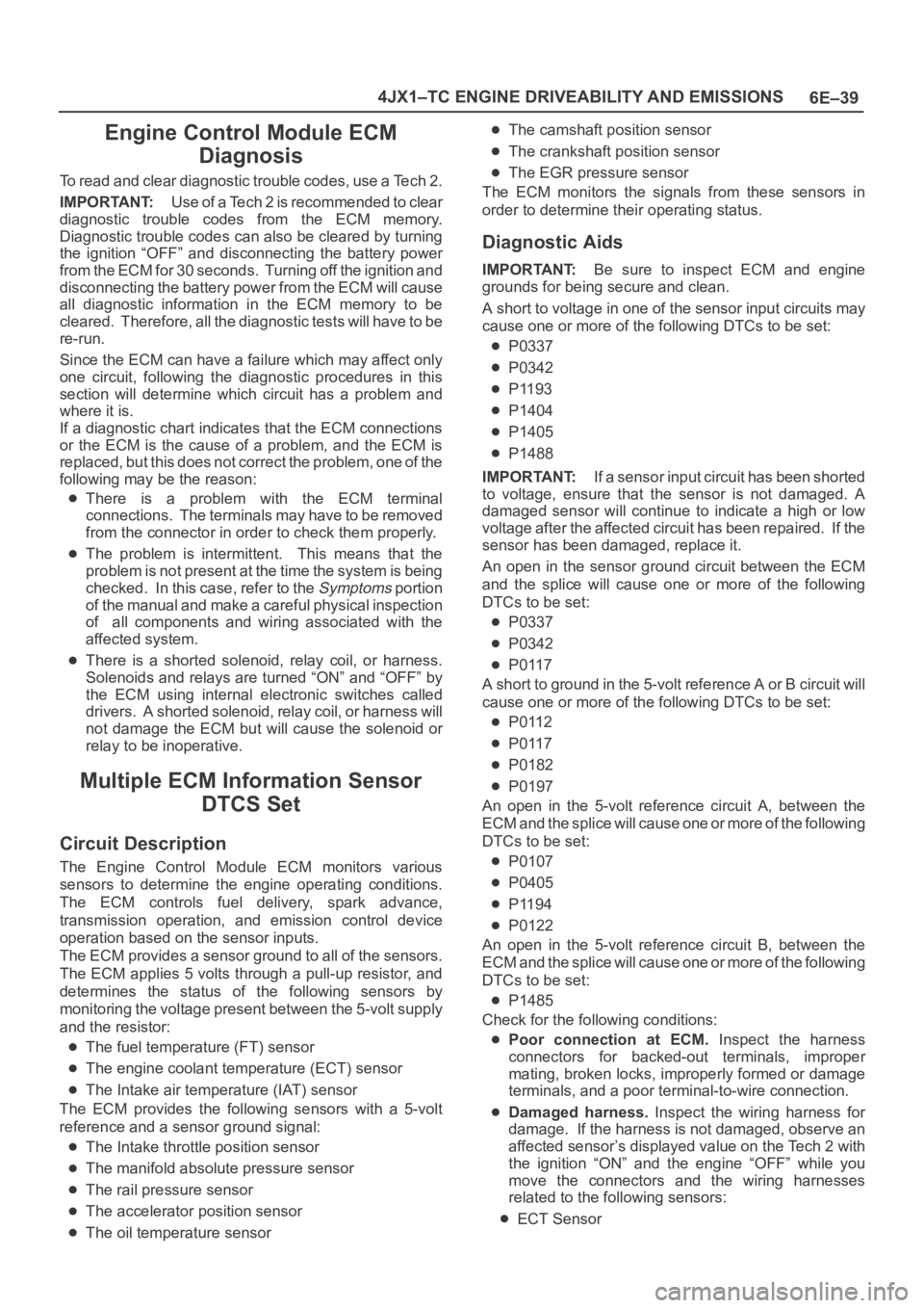
A short to voltage in one of the sensor input circuits may
cause one or more of the following DTCs to be set:
P0337
P0342
P1193
P1404
P1405
P1488
IMPORTANT:If a sensor input circuit has been shorted
to voltage, ensure that the sensor is not damaged. A
damaged sensor will continue to indicate a high or low
voltage after the affected circuit has been repaired. If the
sensor has been damaged, replace it.
An open in the sensor ground circuit between the ECM
and the splice will cause one or more of the following
DTCs to be set:
P0337
P0342
P0117
A short to ground in the 5-volt reference A or B circuit will
cause one or more of the following DTCs to be set:
P0112
P0117
P0182
P0197
An open in the 5-volt reference circuit A, between the
ECM and the splice will cause one or more of the following
DTCs to be set:
P0107
P0405
P1194
P0122
An open in the 5-volt reference circuit B, between the
ECM and the splice will cause one or more of the following
DTCs to be set:
P1485
Check for the following conditions:
Poor connection at ECM. Inspect the harness
connectors for backed-out terminals, improper
mating, broken locks, improperly formed or damage
terminals, and a poor terminal-to-wire connection.
Damaged harness. Inspect the wiring harness for
damage. If the harness is not damaged, observe an
affected sensor’s displayed value on the Tech 2 with
the ignition “ON” and the engine “OFF” while you
move the connectors and the wiring harnesses
related to the following sensors:
ECT Sensor
Page 1948 of 6000
6E–55 4JX1–TC ENGINE DRIVEABILITY AND EMISSIONS
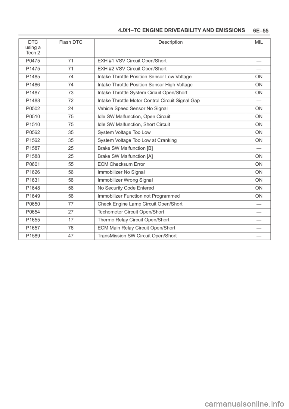
DTC
using a
Te c h 2Flash DTCDescriptionMIL
P047571EXH #1 VSV Circuit Open/Short—
P147571EXH #2 VSV Circuit Open/Short—
P148574Intake Throttle Position Sensor Low VoltageON
P148674Intake Throttle Position Sensor High VoltageON
P148773Intake Throttle System Circuit Open/ShortON
P148872Intake Throttle Motor Control Circuit Signal Gap—
P050224Vehicle Speed Sensor No SignalON
P051075Idle SW Malfunction, Open CircuitON
P151075Idle SW Malfunction, Short CircuitON
P056235System Voltage Too LowON
P156235System Voltage Too Low at CrankingON
P158725Brake SW Malfunction [B]—
P158825Brake SW Malfunction [A]ON
P060155ECM Checksum ErrorON
P162656Immobilizer No SignalON
P163156Immobilizer Wrong SignalON
P164856No Security Code EnteredON
P164956Immobilizer Function not ProgrammedON
P065077Check Engine Lamp Circuit Open/Short—
P065427Techometer Circuit Open/Short—
P165517Thermo Relay Circuit Open/Short—
P165776ECM Main Relay Circuit Open/Short—
P158947TransMission SW Circuit Open/Short—
Page 2080 of 6000
6E–187 4JX1–TC ENGINE DRIVEABILITY AND EMISSIONS
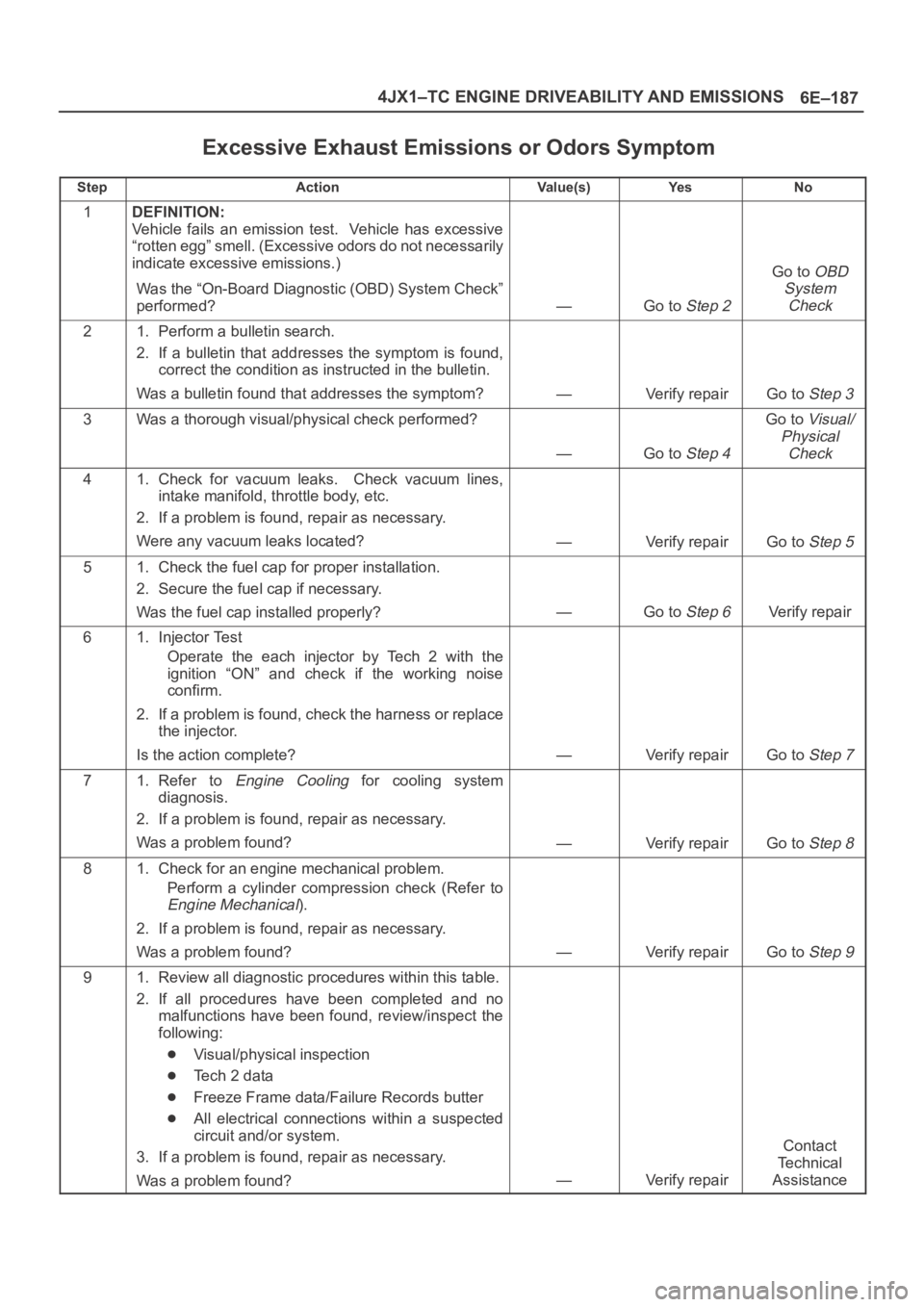
Excessive Exhaust Emissions or Odors Symptom
StepActionVa l u e ( s )Ye sNo
1DEFINITION:
Vehicle fails an emission test. Vehicle has excessive
“rotten egg” smell. (Excessive odors do not necessarily
indicate excessive emissions.)
Was the “On-Board Diagnostic (OBD) System Check”
performed?
—Go to Step 2
Go to OBD
System
Check
21. Perform a bulletin search.
2. If a bulletin that addresses the symptom is found,
correct the condition as instructed in the bulletin.
Was a bulletin found that addresses the symptom?
—Verify repairGo to Step 3
3Was a thorough visual/physical check performed?
—Go to Step 4
Go to Visual/
Physical
Check
41. Check for vacuum leaks. Check vacuum lines,
intake manifold, throttle body, etc.
2. If a problem is found, repair as necessary.
Were any vacuum leaks located?
—Verify repairGo to Step 5
51. Check the fuel cap for proper installation.
2. Secure the fuel cap if necessary.
Was the fuel cap installed properly?
—Go to Step 6Verify repair
61. Injector Test
Operate the each injector by Tech 2 with the
ignition “ON” and check if the working noise
confirm.
2. If a problem is found, check the harness or replace
the injector.
Is the action complete?
—Verify repairGo to Step 7
71. Refer to Engine Cooling for cooling system
diagnosis.
2. If a problem is found, repair as necessary.
Was a problem found?
—Verify repairGo to Step 8
81. Check for an engine mechanical problem.
Perform a cylinder compression check (Refer to
Engine Mechanical).
2. If a problem is found, repair as necessary.
Was a problem found?
—Verify repairGo to Step 9
91. Review all diagnostic procedures within this table.
2. If all procedures have been completed and no
malfunctions have been found, review/inspect the
following:
Visual/physical inspection
Te c h 2 d a t a
Freeze Frame data/Failure Records butter
All electrical connections within a suspected
circuit and/or system.
3. If a problem is found, repair as necessary.
Was a problem found?
—Verify repair
Contact
Te c h n i c a l
Assistance
Page 2103 of 6000
6E–210
4JX1–TC ENGINE DRIVEABILITY AND EMISSIONS
Vehicle Speed Sensor (VSS)
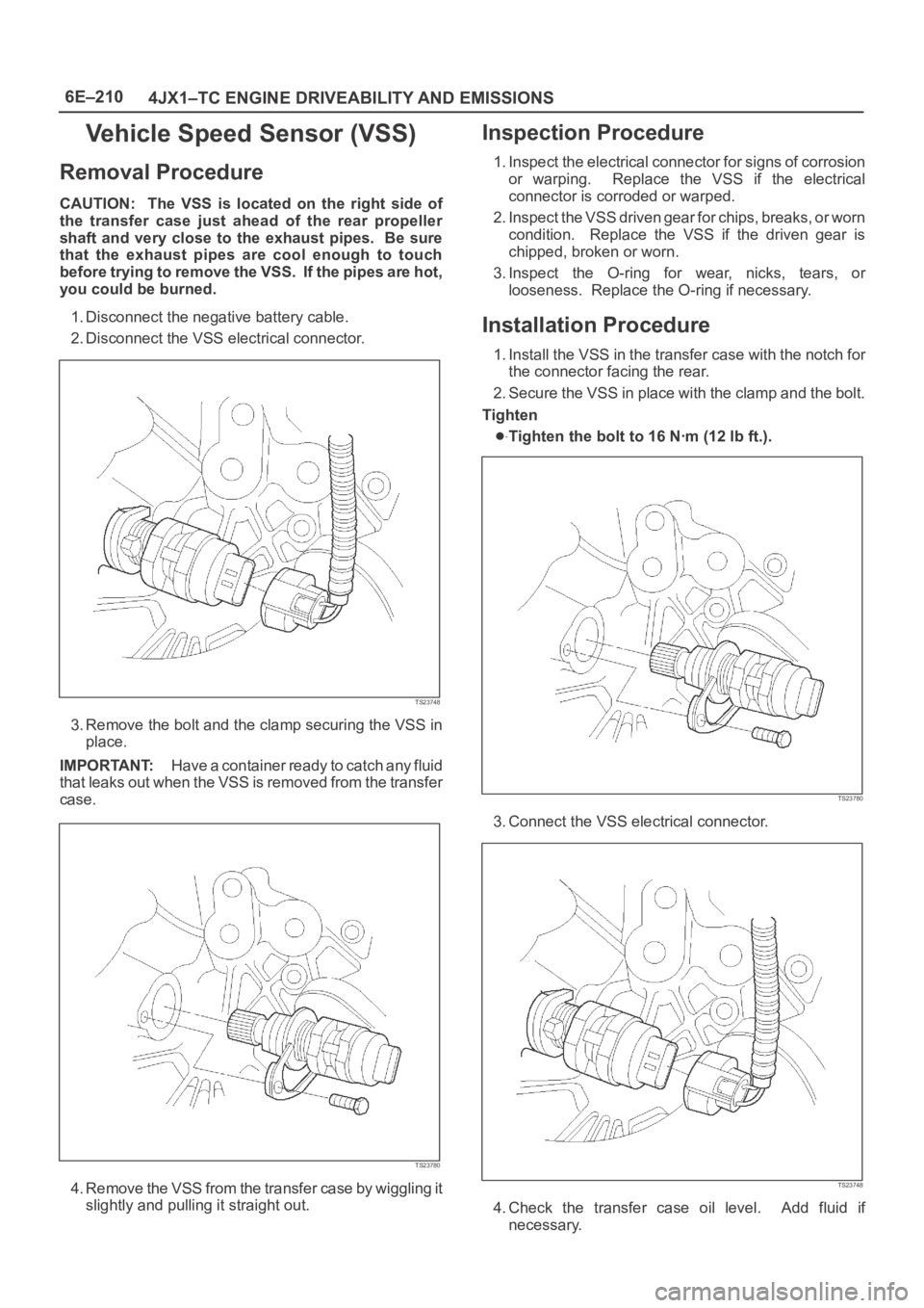
Removal Procedure
CAUTION: The VSS is located on the right side of
the transfer case just ahead of the rear propeller
shaft and very close to the exhaust pipes. Be sure
that the exhaust pipes are cool enough to touch
before trying to remove the VSS. If the pipes are hot,
you could be burned.
1. Disconnect the negative battery cable.
2. Disconnect the VSS electrical connector.
TS23748
3. Remove the bolt and the clamp securing the VSS in
place.
IMPORTANT:H a v e a c o n t a i n e r r e a d y t o c a t c h a n y f l u i d
that leaks out when the VSS is removed from the transfer
case.
TS23780
4. Remove the VSS from the transfer case by wiggling it
slightly and pulling it straight out.
Inspection Procedure
1. Inspect the electrical connector for signs of corrosion
or warping. Replace the VSS if the electrical
connector is corroded or warped.
2. Inspect the VSS driven gear for chips, breaks, or worn
condition. Replace the VSS if the driven gear is
chipped, broken or worn.
3. Inspect the O-ring for wear, nicks, tears, or
looseness. Replace the O-ring if necessary.
Installation Procedure
1. Install the VSS in the transfer case with the notch for
the connector facing the rear.
2. Secure the VSS in place with the clamp and the bolt.
Tighten
Tighten the bolt to 16 Nꞏm (12 lb ft.).
TS23780
3. Connect the VSS electrical connector.
TS23748
4. Check the transfer case oil level. Add fluid if
necessary.
Page 2104 of 6000
6E–211 4JX1–TC ENGINE DRIVEABILITY AND EMISSIONS
5. Connect the negative battery cable.
Air Cleaner/Air Filter
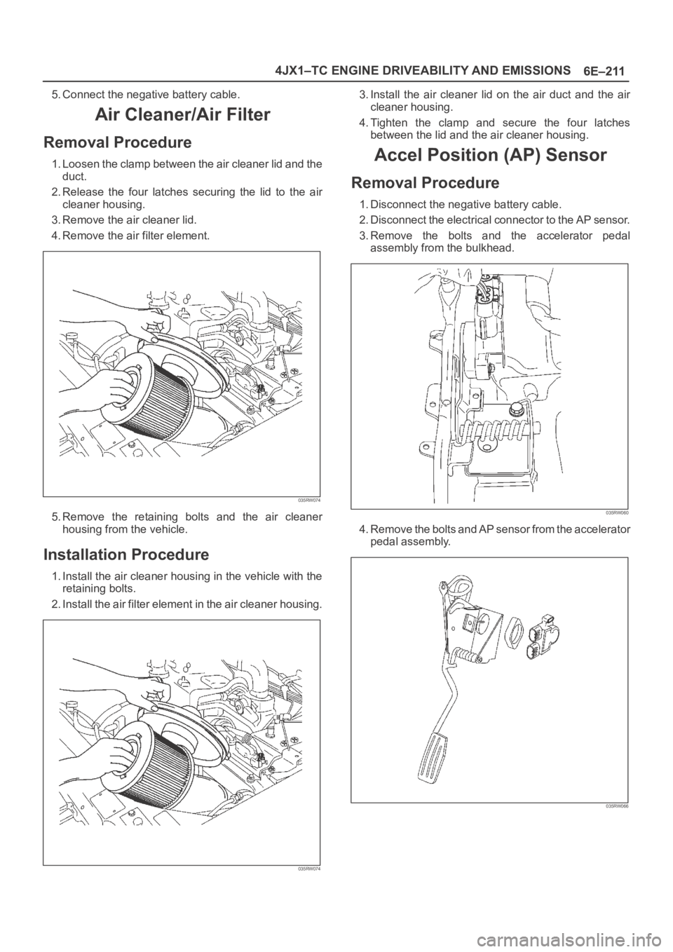
Removal Procedure
1. Loosen the clamp between the air cleaner lid and the
duct.
2. Release the four latches securing the lid to the air
cleaner housing.
3. Remove the air cleaner lid.
4. Remove the air filter element.
035RW074
5. Remove the retaining bolts and the air cleaner
housing from the vehicle.
Installation Procedure
1. Install the air cleaner housing in the vehicle with the
retaining bolts.
2. Install the air filter element in the air cleaner housing.
035RW074
3. Install the air cleaner lid on the air duct and the air
cleaner housing.
4. Tighten the clamp and secure the four latches
between the lid and the air cleaner housing.
Accel Position (AP) Sensor
Removal Procedure
1. Disconnect the negative battery cable.
2. Disconnect the electrical connector to the AP sensor.
3.Remove the bolts and the accelerator pedal
assembly from the bulkhead.
035RW060
4. Remove the bolts and AP sensor from the accelerator
pedal assembly.
035RW066
Page 2114 of 6000
6E–221 4JX1–TC ENGINE DRIVEABILITY AND EMISSIONS
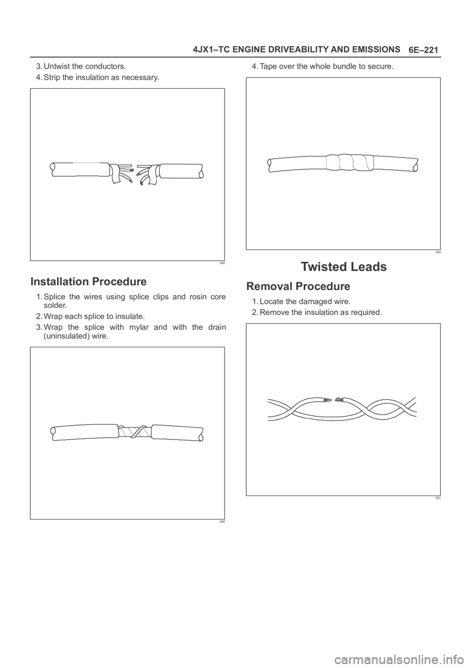
3. Untwist the conductors.
4. Strip the insulation as necessary.
048
Installation Procedure
1. Splice the wires using splice clips and rosin core
solder.
2. Wrap each splice to insulate.
3. Wrap the splice with mylar and with the drain
(uninsulated) wire.
049
4. Tape over the whole bundle to secure.
050
Twisted Leads
Removal Procedure
1. Locate the damaged wire.
2. Remove the insulation as required.
051