Page 1434 of 6000

6E–317 ENGINE DRIVEABILITY AND EMISSIONS
Installation Procedure
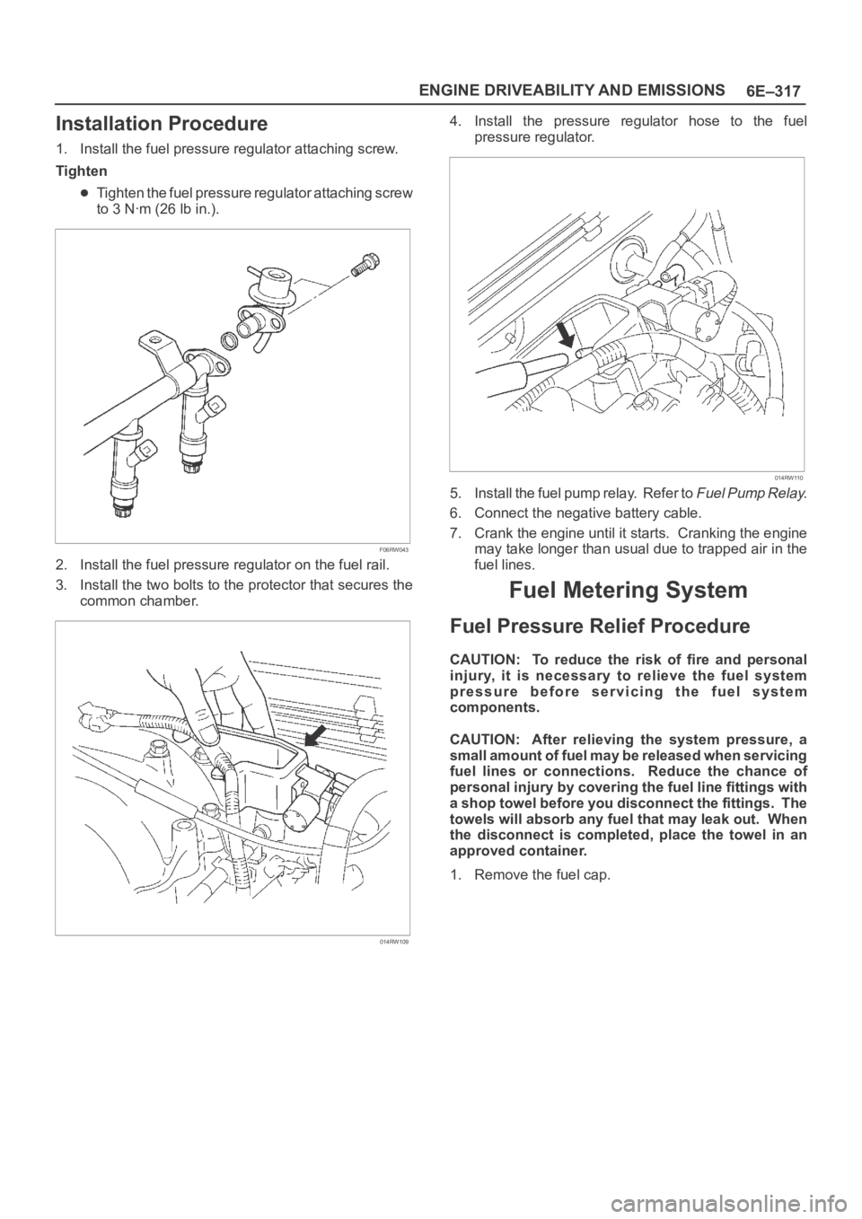
1. Install the fuel pressure regulator attaching screw.
Tighten
Tighten the fuel pressure regulator attaching screw
to 3 Nꞏm (26 lb in.).
F06RW043
2. Install the fuel pressure regulator on the fuel rail.
3. Install the two bolts to the protector that secures the
common chamber.
014RW109
4. Install the pressure regulator hose to the fuel
pressure regulator.
014RW110
5. Install the fuel pump relay. Refer to Fuel Pump Relay.
6. Connect the negative battery cable.
7. Crank the engine until it starts. Cranking the engine
may take longer than usual due to trapped air in the
fuel lines.
Fuel Metering System
Fuel Pressure Relief Procedure
CAUTION: To reduce the risk of fire and personal
injury, it is necessary to relieve the fuel system
pressure before servicing the fuel system
components.
CAUTION: After relieving the system pressure, a
small amount of fuel may be released when servicing
fuel lines or connections. Reduce the chance of
personal injury by covering the fuel line fittings with
a shop towel before you disconnect the fittings. The
towels will absorb any fuel that may leak out. When
the disconnect is completed, place the towel in an
approved container.
1. Remove the fuel cap.
Page 1439 of 6000
6E–322
ENGINE DRIVEABILITY AND EMISSIONS
15. Remove the fuel tank retaining bolts on both sides.
16. Remove the fuel tank.
TS23770
Installation Procedure
1. Install the fuel tank.
Place the flanges on the left and right side of the
tank on the bracket.
2. Install the fuel tank retaining bolts.
Tighten
Tighten the fuel tank retaining bolts to 36 Nꞏm (27 lb
ft.).
TS23770
3. Connect the fuel return hose.
4. Connect the fuel supply hose.
5. Connect the EVAP vapor hose.
6. Connect the wiring connector for the fuel gauge unit.
7. Connect the fuel gauge wiring connector to the
bracket.
8. Connect the wiring connector for the fuel pump.
TS23769
9. Install the undercover.
10. Secure the undercover with the retaining bolts.
TS23797
Page 1441 of 6000

6E–324
ENGINE DRIVEABILITY AND EMISSIONS
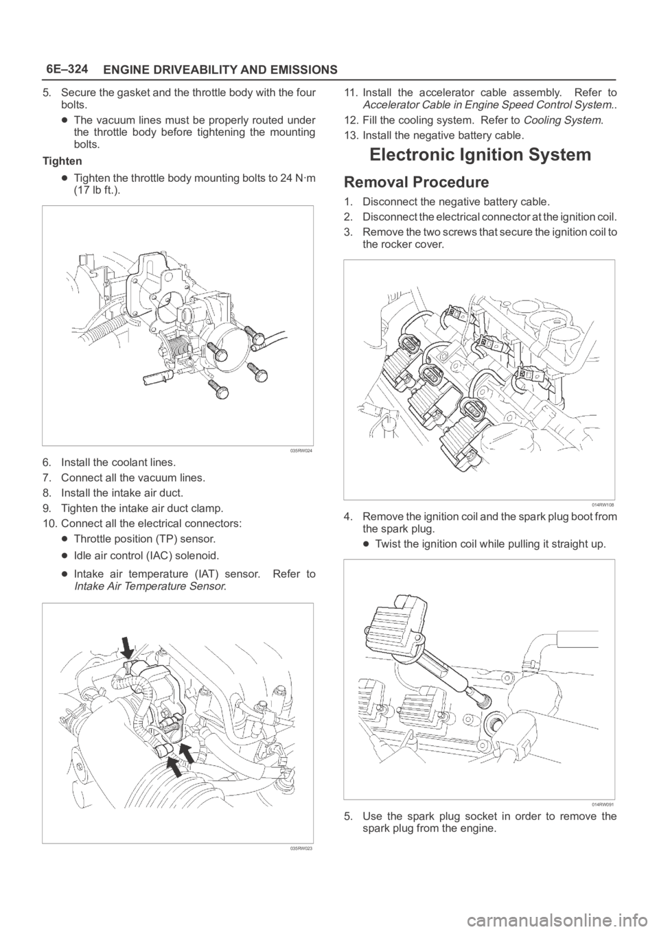
5. Secure the gasket and the throttle body with the four
bolts.
The vacuum lines must be properly routed under
the throttle body before tightening the mounting
bolts.
Tighten
Tighten the throttle body mounting bolts to 24 Nꞏm
(17 lb ft.).
035RW024
6. Install the coolant lines.
7. Connect all the vacuum lines.
8. Install the intake air duct.
9. Tighten the intake air duct clamp.
10. Connect all the electrical connectors:
Throttle position (TP) sensor.
Idle air control (IAC) solenoid.
Intake air temperature (IAT) sensor. Refer to
Intake Air Temperature Sensor.
035RW023
11. Install the accelerator cable assembly. Refer to
Accelerator Cable in Engine Speed Control System..
12. Fill the cooling system. Refer to
Cooling System.
13. Install the negative battery cable.
Electronic Ignition System
Removal Procedure
1. Disconnect the negative battery cable.
2. Disconnect the electrical connector at the ignition coil.
3. Remove the two screws that secure the ignition coil to
the rocker cover.
014RW108
4. Remove the ignition coil and the spark plug boot from
the spark plug.
Twist the ignition coil while pulling it straight up.
014RW091
5. Use the spark plug socket in order to remove the
spark plug from the engine.
Page 1442 of 6000

6E–325 ENGINE DRIVEABILITY AND EMISSIONS
Spark Plug Gap Check
Check the gap of all spark plugs before installation.
Use a round wire feeler gauge to ensure an accurate
check.
Plugs installed with the wrong gap can cause poor
engine performance and excessive emissions.
Installation Procedure
NOTE: The plug must thread smoothly into the cylinder
head and be fully seated. Use a thread chaser if
necessary to clean the threads in the cylinder head.
Cross-threading or failure to fully seat the spark plug can
cause plug overheating, exhaust blow-by gas, or thread
damage. Do not overtighten the spark plugs. Over
tightening can cause aluminum threads to strip.
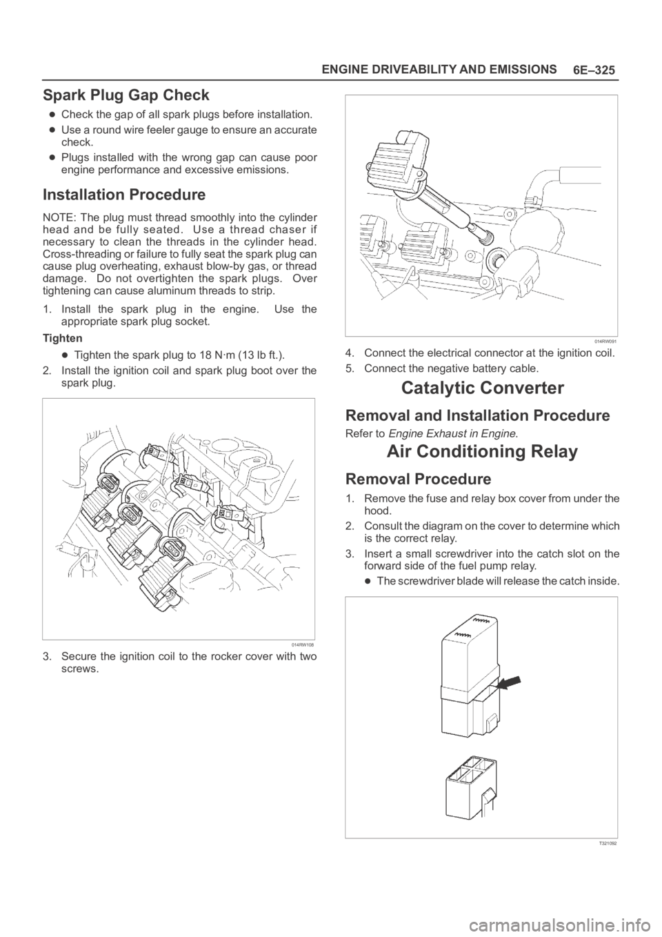
1. Install the spark plug in the engine. Use the
appropriate spark plug socket.
Tighten
Tighten the spark plug to 18 Nꞏm (13 lb ft.).
2. Install the ignition coil and spark plug boot over the
spark plug.
014RW108
3. Secure the ignition coil to the rocker cover with two
screws.
014RW091
4. Connect the electrical connector at the ignition coil.
5. Connect the negative battery cable.
Catalytic Converter
Removal and Installation Procedure
Refer to Engine Exhaust in Engine.
Air Conditioning Relay
Removal Procedure
1. Remove the fuse and relay box cover from under the
hood.
2. Consult the diagram on the cover to determine which
is the correct relay.
3. Insert a small screwdriver into the catch slot on the
forward side of the fuel pump relay.
The screwdriver blade will release the catch inside.
T321092
Page 1445 of 6000
6E–328
ENGINE DRIVEABILITY AND EMISSIONS
3. Connect the vacuum hoses to the EVAP canister
purge solenoid.
014RW137
4. Connect the electrical connector to the EVAP canister
purge solenoid.
014RW138
Fuel Tank Vent Valve
Removal and Installation Procedure
Refer to Fuel Pump
Linear Exhaust Gas
Recirculation (EGR) Valve
Removal Procedure
1. Disconnect the negative battery cable.2. Disconnect the electrical connector at the EGR valve.
014RW139
3. Remove the bolt and the nut from the upper intake
manifold.
014RW098
4. Remove the EGR valve from the upper intake
manifold.
5. Remove the gasket from the upper intake manifold.
Installation Procedure
1. Install the gasket on the upper intake manifold.
2. Install the EGR valve on the upper intake manifold.
3. Secure the EGR valve and the gasket with the bolt
and the nut.
Page 1446 of 6000
6E–329 ENGINE DRIVEABILITY AND EMISSIONS
NOTE: It is possible to install the EGR valve rotated 180
from the correct position. Make sure that the base of the
valve is placed so that it aligns with the mounting flange.
014RW098
4. Connect the electrical connector at the EGR valve.
014RW139
5. Connect the negative battery cable.
Positive Crankcase Ventilation
(PCV) Valve
Removal Procedure
1. Remove the vacuum hose at the PCV valve.
Slide the clamp back to release the hose.2. Pull the PCV valve from the rubber grommet in the
right valve cover.
014RW097
Inspection Procedure
1. Shake the valve and listen for the rattle of the needle
inside the valve.
2. If the valve does not rattle, replace the valve.
Installation Procedure
1. Push the PCV valve into the rubber grommet in the
left valve cover.
2. Install the vacuum hose on the PCV valve and secure
the vacuum hose with the clamp.
014RW097
Page 1448 of 6000
6E–331 ENGINE DRIVEABILITY AND EMISSIONS
Installation Procedure
1. Splice the wires using splice clips and rosin core
solder.
2. Wrap each splice to insulate.
3. Wrap the splice with mylar and with the drain
(uninsulated) wire.
049
4. Tape over the whole bundle to secure.
050
Twisted Leads
Removal Procedure
1. Locate the damaged wire.
2. Remove the insulation as required.
051
Installation Procedure
1. Use splice clips and rosin core solder in order to splice
the two wires together.
052
Page 1454 of 6000

6E–337 ENGINE DRIVEABILITY AND EMISSIONS
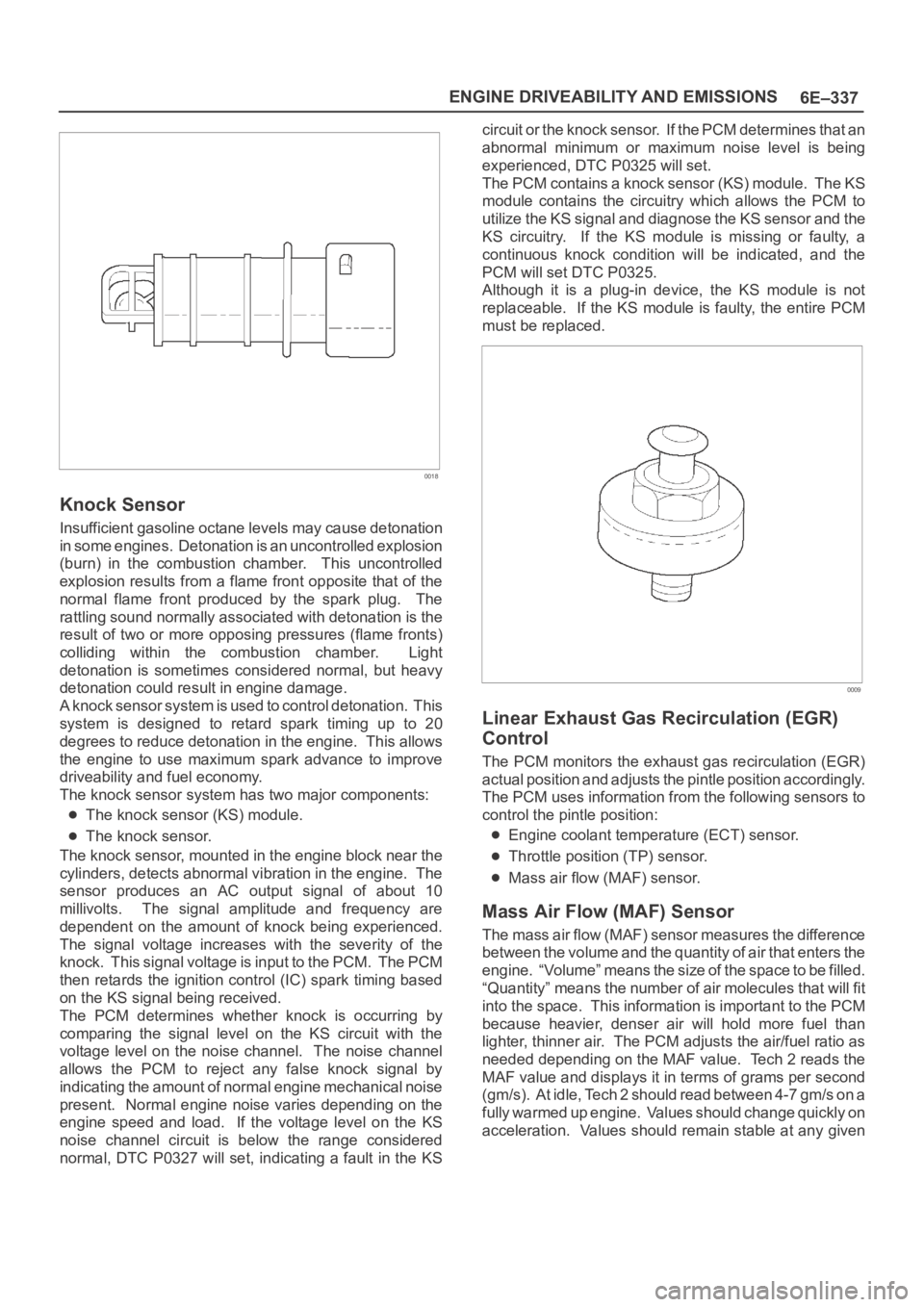
0018
Knock Sensor
Insufficient gasoline octane levels may cause detonation
in some engines. Detonation is an uncontrolled explosion
(burn) in the combustion chamber. This uncontrolled
explosion results from a flame front opposite that of the
normal flame front produced by the spark plug. The
rattling sound normally associated with detonation is the
result of two or more opposing pressures (flame fronts)
colliding within the combustion chamber. Light
detonation is sometimes considered normal, but heavy
detonation could result in engine damage.
A knock sensor system is used to control detonation. This
system is designed to retard spark timing up to 20
degrees to reduce detonation in the engine. This allows
the engine to use maximum spark advance to improve
driveability and fuel economy.
The knock sensor system has two major components:
The knock sensor (KS) module.
The knock sensor.
The knock sensor, mounted in the engine block near the
cylinders, detects abnormal vibration in the engine. The
sensor produces an AC output signal of about 10
millivolts. The signal amplitude and frequency are
dependent on the amount of knock being experienced.
The signal voltage increases with the severity of the
knock. This signal voltage is input to the PCM. The PCM
then retards the ignition control (IC) spark timing based
on the KS signal being received.
The PCM determines whether knock is occurring by
comparing the signal level on the KS circuit with the
voltage level on the noise channel. The noise channel
allows the PCM to reject any false knock signal by
indicating the amount of normal engine mechanical noise
present. Normal engine noise varies depending on the
engine speed and load. If the voltage level on the KS
noise channel circuit is below the range considered
normal, DTC P0327 will set, indicating a fault in the KScircuit or the knock sensor. If the PCM determines that an
abnormal minimum or maximum noise level is being
experienced, DTC P0325 will set.
The PCM contains a knock sensor (KS) module. The KS
module contains the circuitry which allows the PCM to
utilize the KS signal and diagnose the KS sensor and the
KS circuitry. If the KS module is missing or faulty, a
continuous knock condition will be indicated, and the
PCM will set DTC P0325.
Although it is a plug-in device, the KS module is not
replaceable. If the KS module is faulty, the entire PCM
must be replaced.
0009
Linear Exhaust Gas Recirculation (EGR)
Control
The PCM monitors the exhaust gas recirculation (EGR)
actual position and adjusts the pintle position accordingly.
The PCM uses information from the following sensors to
control the pintle position:
Engine coolant temperature (ECT) sensor.
Throttle position (TP) sensor.
Mass air flow (MAF) sensor.
Mass Air Flow (MAF) Sensor
The mass air flow (MAF) sensor measures the difference
between the volume and the quantity of air that enters the
engine. “Volume” means the size of the space to be filled.
“Quantity” means the number of air molecules that will fit
into the space. This information is important to the PCM
because heavier, denser air will hold more fuel than
lighter, thinner air. The PCM adjusts the air/fuel ratio as
needed depending on the MAF value. Tech 2 reads the
MAF value and displays it in terms of grams per second
(gm/s). At idle, Tech 2 should read between 4-7 gm/s on a
fully warmed up engine. Values should change quickly on
acceleration. Values should remain stable at any given