1998 OPEL FRONTERA ECU
[x] Cancel search: ECUPage 1216 of 6000
6E–99 ENGINE DRIVEABILITY AND EMISSIONS
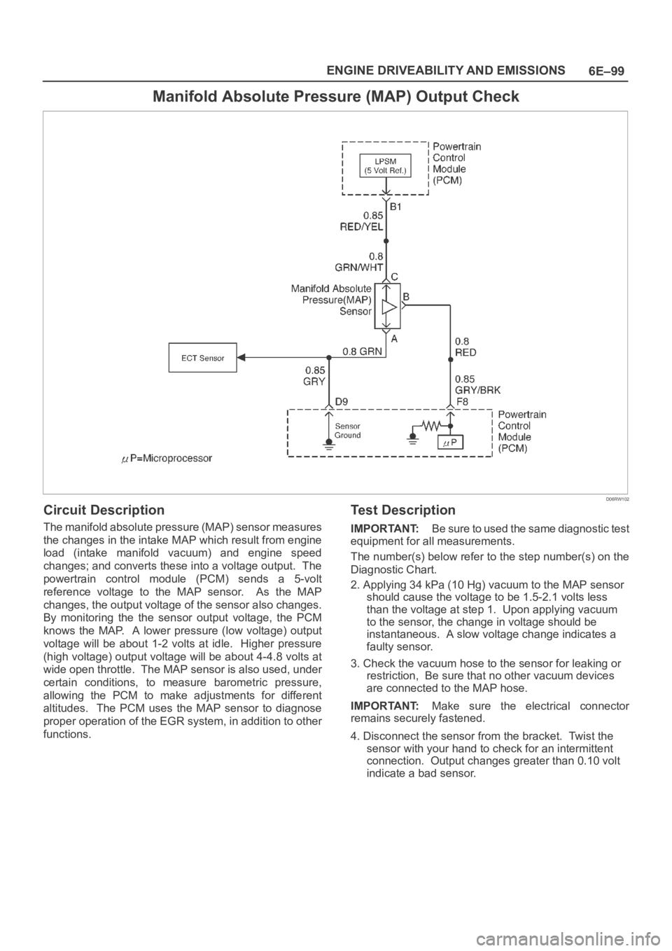
Manifold Absolute Pressure (MAP) Output Check
D06RW102
Circuit Description
The manifold absolute pressure (MAP) sensor measures
the changes in the intake MAP which result from engine
load (intake manifold vacuum) and engine speed
changes; and converts these into a voltage output. The
powertrain control module (PCM) sends a 5-volt
reference voltage to the MAP sensor. As the MAP
changes, the output voltage of the sensor also changes.
By monitoring the the sensor output voltage, the PCM
knows the MAP. A lower pressure (low voltage) output
voltage will be about 1-2 volts at idle. Higher pressure
(high voltage) output voltage will be about 4-4.8 volts at
wide open throttle. The MAP sensor is also used, under
certain conditions, to measure barometric pressure,
allowing the PCM to make adjustments for different
altitudes. The PCM uses the MAP sensor to diagnose
proper operation of the EGR system, in addition to other
functions.
Test Description
IMPORTANT:Be sure to used the same diagnostic test
equipment for all measurements.
The number(s) below refer to the step number(s) on the
Diagnostic Chart.
2. Applying 34 kPa (10 Hg) vacuum to the MAP sensor
should cause the voltage to be 1.5-2.1 volts less
than the voltage at step 1. Upon applying vacuum
to the sensor, the change in voltage should be
instantaneous. A slow voltage change indicates a
faulty sensor.
3. Check the vacuum hose to the sensor for leaking or
restriction, Be sure that no other vacuum devices
are connected to the MAP hose.
IMPORTANT:Make sure the electrical connector
remains securely fastened.
4. Disconnect the sensor from the bracket. Twist the
sensor with your hand to check for an intermittent
connection. Output changes greater than 0.10 volt
indicate a bad sensor.
Page 1218 of 6000

6E–101 ENGINE DRIVEABILITY AND EMISSIONS
PCM Diagnostic Trouble Codes
The following table lists the diagnostic trouble codes
supported by this vehicle application. If any DTCs not
listed here are displayed by a Tech 2, the Tech 2 data may
be faulty; notify the Tech 2 manufacturer of any DTCs
displayed that are not included in the following table.
A - Emission related P-code, check engine light on as
soon as a failure detected.
B - Emission related P-code, check engine light on if a
failure detected in two consecutive trips.
C - Non emission related P-code, check engine light on
if a failure detected in one trip.
D - Non emission related P-code, no check engine
light, but P-code will be set if a failure detected.
X - Do not check.
Page 1221 of 6000
6E–104
ENGINE DRIVEABILITY AND EMISSIONS
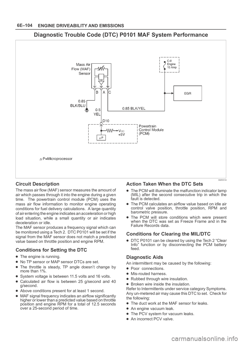
Diagnostic Trouble Code (DTC) P0101 MAF System Performance
D06RW103
Circuit Description
The mass air flow (MAF) sensor measures the amount of
air which passes through it into the engine during a given
time. The powertrain control module (PCM) uses the
mass air flow information to monitor engine operating
conditions for fuel delivery calculations. A large quantity
of air entering the engine indicates an acceleration or high
load situation, while a small quantity or air indicates
deceleration or idle.
The MAF sensor produces a frequency signal which can
be monitored using a Tech 2. DTC P0101 will be set if the
signal from the MAF sensor does not match a predicted
value based on throttle position and engine RPM.
Conditions for Setting the DTC
The engine is running.
No TP sensor or MAP sensor DTCs are set.
The throttle is steady, TP angle doesn’t change by
more than 1%.
System voltage is between 11.5 volts and 16 volts.
Calculated air flow is between 25 g/second and 40
g/second.
Above conditions present for at least 1 second.
MAF signal frequency indicates an airflow significantly
higher or lower than a predicted value based on throttle
position and engine RPM for a total of 12.5 seconds
over a 25-second period of time.
Action Taken When the DTC Sets
The PCM will illuminate the malfunction indicator lamp
(MIL) after the second consecutive trip in which the
fault is detected.
The PCM calculates an airflow value based on idle air
control valve position, throttle position, RPM and
barometric pressure.
The PCM will store conditions which were present
when the DTC was set as Freeze Frame and in the
Failure Records data.
Conditions for Clearing the MIL/DTC
DTC P0101 can be cleared by using the Tech 2 “Clear
Info” function or by disconnecting the PCM battery
feed.
Diagnostic Aids
An intermittent may be caused by the following:
Poor connections.
Mis-routed harness.
Rubbed through wire insulation.
Broken wire inside the insulation.
Refer to Intermittents under service category Symptoms.
Any un-metered air may cause this DTC to set. Check for
the following:
The duct work at the MAF sensor for leaks.
An engine vacuum leak.
The PCV system for vacuum leaks.
An incorrect PCV valve.
Page 1247 of 6000
6E–130
ENGINE DRIVEABILITY AND EMISSIONS
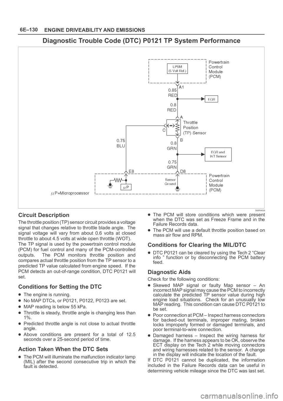
Diagnostic Trouble Code (DTC) P0121 TP System Performance
D06RW028
Circuit Description
The throttle position (TP) sensor circuit provides a voltage
signal that changes relative to throttle blade angle. The
signal voltage will vary from about 0.6 volts at closed
throttle to about 4.5 volts at wide open throttle (WOT).
The TP signal is used by the powertrain control module
(PCM) for fuel control and many of the PCM-controlled
outputs. The PCM monitors throttle position and
compares actual throttle position from the TP sensor to a
predicted TP value calculated from engine speed. If the
PCM detects an out-of-range condition, DTC P0121 will
set.
Conditions for Setting the DTC
The engine is running.
No MAP DTCs, or P0121, P0122, P0123 are set.
MAP reading is below 55 kPa.
Throttle is steady, throttle angle is changing less than
1%.
Predicted throttle angle is not close to actual throttle
angle.
Above conditions are present for a total of 12.5
seconds over a 25-second period of time.
Action Taken When the DTC Sets
The PCM will illuminate the malfunction indicator lamp
(MIL) after the second consecutive trip in which the
fault is detected.
The PCM will store conditions which were present
when the DTC was set as Freeze Frame and in the
Failure Records data.
The PCM will use a default throttle position based on
mass air flow and RPM.
Conditions for Clearing the MIL/DTC
DTC P0121 can be cleared by using the Tech 2 “Clear
info ” function or by disconnecting the PCM battery
feed.
Diagnostic Aids
Check for the following conditions:
Skewed MAP signal or faulty Map sensor – An
incorrect MAP signal may cause the PCM to incorrectly
calculate the predicted TP sensor value during high
engine load situations. Check for an unusually low
MAP reading. This condition can cause DTC P0121 to
be set.
Poor connection at PCM – Inspect harness connectors
for backed-out terminals, improper mating, broken
locks improperly formed or damaged terminals, and
poor terminal-to-wire connection.
Damaged harness – Inspect the wiring harness for
damage. If the harness appears to be OK, observe the
ECT display on the Tech 2 while moving connectors
and wiring harnesses related to the sensor. A change
in the display will indicate the location of the fault.
If DTC P0121 cannot be duplicated, the information
included in the Failure Records data can be useful in
determining vehicle mileage since the DTC was last set.
Page 1272 of 6000
6E–155 ENGINE DRIVEABILITY AND EMISSIONS
Mass air flow is between 2 g/second and 200 g/second.
Ignition voltage is above 9.5 volts.
Fuel system is in “closed loop.”
Action Taken When the DTC Sets
The PCM will illuminate the malfunction indicator lamp
(MIL) after the second consecutive trip in which the
fault is detected.
The PCM will store conditions which were present
when the DTC was set as Freeze Frame and in the
Failure Records data.
Conditions for Clearing the MIL/DTC
DTC P0171 can be cleared by using the Tech 2 “Clear
Info” function or by disconnecting the PCM battery
feed.
Diagnostic Aids
Check for the following conditions:
Poor connection at PCM – Inspect harness connectors
for backed-out terminals, improper mating, broken
locks, improperly formed or damaged terminals, and
poor terminal-to-wire connection.
Damaged harness – Inspect the wiring harness for
damage. If the harness appears to be OK, observe the
Bank 1 HO2S 1 display on the Tech 2 while moving
connectors and wiring harnesses related to the engine
harness. A change in the display will indicate the
location of the fault.
Reviewing the Failure Records vehicle mileage since the
diagnostic test last failed may help determine how often
the condition that caused the DTC to be set occurs. This
may assist in diagnosing the condition.
Test Description
Number(s) below refer to the step number(s) on the
Diagnostic Chart.
2. DTCs other than P0171 and P0174 may indicate a
condition present which may cause a lean condition.
If this is the case, repairing the condition which
caused the other DTC will most likely correct the
DTC P0171/P0174.
4. If the DTC P0171 test passes while the Failure
Records conditions are being duplicated, the lean
condition is intermittent. Refer to
Diagnostic Aids or
Symptoms for additional information on diagnosing
intermittent problems.
Page 1274 of 6000
6E–157 ENGINE DRIVEABILITY AND EMISSIONS
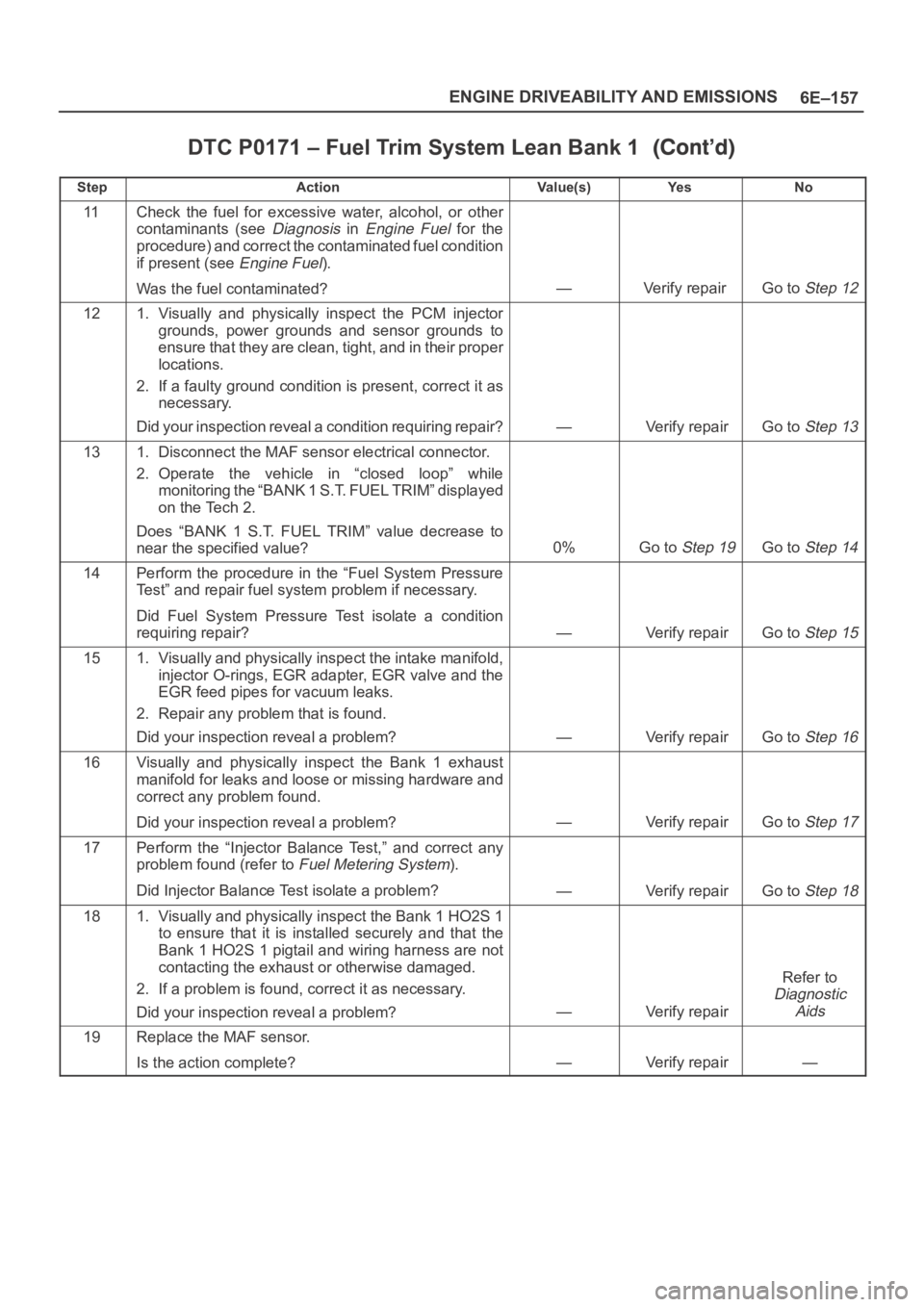
DTC P0171 – Fuel Trim System Lean Bank 1
StepNo Ye s Va l u e ( s ) Action
11Check the fuel for excessive water, alcohol, or other
contaminants (see
Diagnosis in Engine Fuel for the
procedure) and correct the contaminated fuel condition
if present (see
Engine Fuel).
Was the fuel contaminated?
—Verify repair Go to Step 12
121. Visually and physically inspect the PCM injector
grounds, power grounds and sensor grounds to
ensure that they are clean, tight, and in their proper
locations.
2. If a faulty ground condition is present, correct it as
necessary.
Did your inspection reveal a condition requiring repair?
—Verify repairGo to Step 13
131. Disconnect the MAF sensor electrical connector.
2. Operate the vehicle in “closed loop” while
monitoring the “BANK 1 S.T. FUEL TRIM” displayed
on the Tech 2.
Does “BANK 1 S.T. FUEL TRIM” value decrease to
near the specified value?
0%Go to Step 19Go to Step 14
14Perform the procedure in the “Fuel System Pressure
Test” and repair fuel system problem if necessary.
Did Fuel System Pressure Test isolate a condition
requiring repair?
—Verify repairGo to Step 15
151. Visually and physically inspect the intake manifold,
injector O-rings, EGR adapter, EGR valve and the
EGR feed pipes for vacuum leaks.
2. Repair any problem that is found.
Did your inspection reveal a problem?
—Verify repairGo to Step 16
16Visually and physically inspect the Bank 1 exhaust
manifold for leaks and loose or missing hardware and
correct any problem found.
Did your inspection reveal a problem?
—Verify repairGo to Step 17
17Perform the “Injector Balance Test,” and correct any
problem found (refer to
Fuel Metering System).
Did Injector Balance Test isolate a problem?
—Verify repairGo to Step 18
181. Visually and physically inspect the Bank 1 HO2S 1
to ensure that it is installed securely and that the
Bank 1 HO2S 1 pigtail and wiring harness are not
contacting the exhaust or otherwise damaged.
2. If a problem is found, correct it as necessary.
Did your inspection reveal a problem?
—Verify repair
Refer to
Diagnostic
Aids
19Replace the MAF sensor.
Is the action complete?
—Verify repair—
Page 1276 of 6000
6E–159 ENGINE DRIVEABILITY AND EMISSIONS
Vehicle speed is below 136 km/h (85 mph).
Engine speed is between 400 and 6,000 RPM.
Barometric pressure is greater than 72.5 kPa.
Mass air flow is between 2 g/second and 200 g/second.
Ignition voltage is above 9.5 volts.
Fuel system is in “closed loop.”
Action Taken When the DTC Sets
The PCM will illuminate the malfunction indicator lamp
(MIL) after the second consecutive trip in which the
fault is detected.
The PCM will store conditions which were present
when the DTC was set as Freeze Frame and in the
Failure Records data.
Conditions for Clearing the MIL/DTC
DTC P0172 can be cleared by using the Tech 2 “Clear
Info” function or by disconnecting the PCM battery
feed.
Diagnostic Aids
Check for the following conditions:
Poor connection at PCM – Inspect harness connectors
for backed-out terminals, improper mating, broken
locks, improperly formed or damaged terminals, and
poor terminal-to-wire connection.
Damaged harness – Inspect the wiring harness for
damage. If the harness appears to be OK, observe the
Bank 1 HO2S 1 display on the Tech 2 while moving
connectors and wiring harnesses related to the engine
harness. A change in the display will indicate the
location of the fault.
Reviewing the Failure Records vehicle mileage since the
diagnostic test last failed may help determine how often
the condition that caused the DTC to be set occurs. This
may assist in diagnosing the condition.
Test Description
Number(s) below refer to the step number(s) on the
Diagnostic Chart.
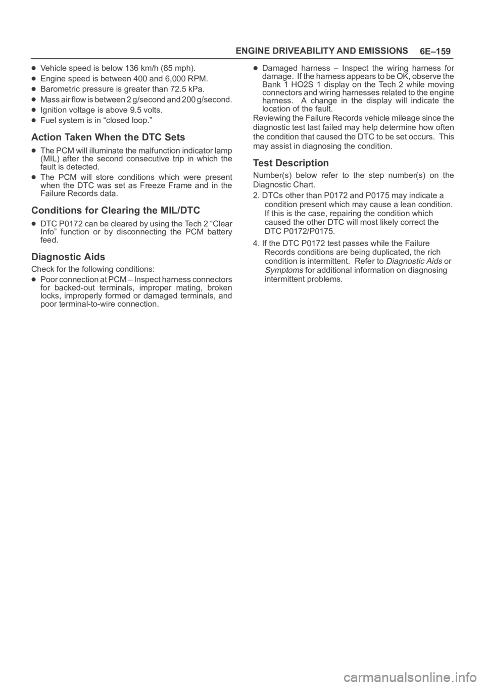
2. DTCs other than P0172 and P0175 may indicate a
condition present which may cause a lean condition.
If this is the case, repairing the condition which
caused the other DTC will most likely correct the
DTC P0172/P0175.
4. If the DTC P0172 test passes while the Failure
Records conditions are being duplicated, the rich
condition is intermittent. Refer to
Diagnostic Aids or
Symptoms for additional information on diagnosing
intermittent problems.
Page 1280 of 6000
6E–163 ENGINE DRIVEABILITY AND EMISSIONS
Ignition voltage is above 9.5 volts.
Fuel system is in “closed loop.”
Action Taken When the DTC Sets
The PCM will illuminate the malfunction indicator lamp
(MIL) after the second consecutive trip in which the
failure is detected.
The PCM will store conditions which were present
when the DTC was set as Freeze Frame and in the
Failure Records data.
Conditions for Clearing the MIL/DTC
DTC P0174 can be cleared by using the Tech 2 “Clear
Info” function or by disconnecting the PCM battery
feed.
Diagnostic Aids
Check for the following conditions:
Poor connection at PCM – Inspect harness connectors
for backed-out terminals, improper mating, broken
locks, improperly formed or damaged terminals, and
poor terminal-to-wire connection.
Damaged harness – Inspect the wiring harness for
damage. If the harness appears to be OK, observe theBank 2 HO2S 1 display on the Tech 2 while moving
connectors and wiring harnesses related to the engine
harness. A change in the display will indicate the
location of the fault.
Reviewing the Failure Records vehicle mileage since the
diagnostic test last failed may help determine how often
the condition that caused the DTC to be set occurs. This
may assist in diagnosing the condition.
Test Description
Number(s) below refer to the step number(s) on the
Diagnostic Chart.
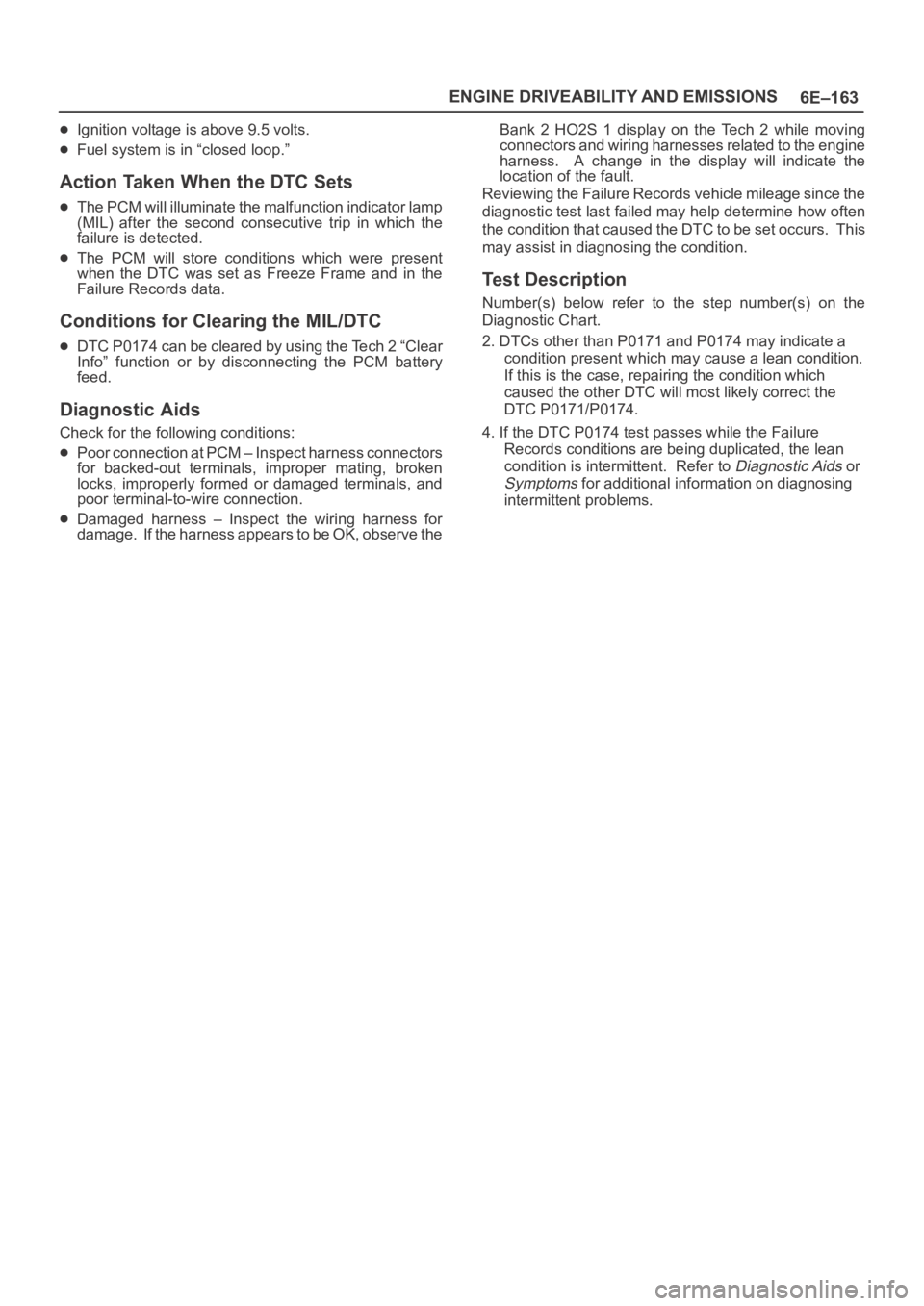
2. DTCs other than P0171 and P0174 may indicate a
condition present which may cause a lean condition.
If this is the case, repairing the condition which
caused the other DTC will most likely correct the
DTC P0171/P0174.
4. If the DTC P0174 test passes while the Failure
Records conditions are being duplicated, the lean
condition is intermittent. Refer to
Diagnostic Aids or
Symptoms for additional information on diagnosing
intermittent problems.