Page 2269 of 6000

7A1–24
TRANSMISSION CONTROL SYSTEM (4L30–E)
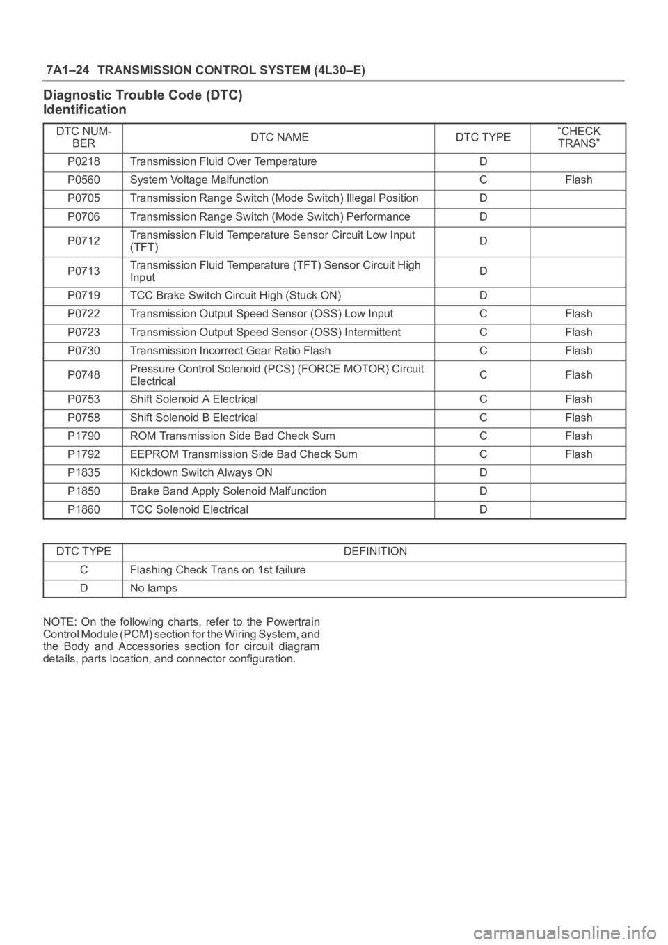
Diagnostic Trouble Code (DTC)
Identification
DTC NUM-
BERDTC NAMEDTC TYPE“CHECK
TRANS”
P0218Transmission Fluid Over TemperatureD
P0560System Voltage MalfunctionCFlash
P0705Transmission Range Switch (Mode Switch) Illegal PositionD
P0706Transmission Range Switch (Mode Switch) PerformanceD
P0712Transmission Fluid Temperature Sensor Circuit Low Input
(TFT)D
P0713Transmission Fluid Temperature (TFT) Sensor Circuit High
InputD
P0719TCC Brake Switch Circuit High (Stuck ON)D
P0722Transmission Output Speed Sensor (OSS) Low InputCFlash
P0723Transmission Output Speed Sensor (OSS) IntermittentCFlash
P0730Transmission Incorrect Gear Ratio FlashCFlash
P0748Pressure Control Solenoid (PCS) (FORCE MOTOR) Circuit
ElectricalCFlash
P0753Shift Solenoid A ElectricalCFlash
P0758Shift Solenoid B ElectricalCFlash
P1790ROM Transmission Side Bad Check SumCFlash
P1792EEPROM Transmission Side Bad Check SumCFlash
P1835Kickdown Switch Always OND
P1850Brake Band Apply Solenoid MalfunctionD
P1860TCC Solenoid ElectricalD
DTC TYPEDEFINITION
CFlashing Check Trans on 1st failure
DNo lamps
NOTE: On the following charts, refer to the Powertrain
Control Module (PCM) section for the Wiring System, and
the Body and Accessories section for circuit diagram
details, parts location, and connector configuration.
Page 2597 of 6000

The chassis electrical system is a 12–volt system with a
negative ground polarity.
Wire size are appropriate to respective circuits, and
classified by color. (The classification of harnesses by
color is shown on the circuit diagram for ease of harness
identification.)
The wire size is determined by load capacity and the
length of wire required.
The vehicle harnesses are: body harness, chassis
harness, engine room harness, instrument harness,
transmission harness, engine ECGI harness, dome light
harness, door harness, rear body harness, tailgate
harness, SRS harness and battery cables.
The harnesses are protected either by tape or corrugated
tube, depending on harness location.
The circuit for each system consists of the power source,
wire, fuse, relay, switch, load parts and ground, all of
which are shown on the circuit diagram.
In this section, each electrical device is classified by
system.
For major parts shown on the circuit based on the circuit
diagram for each system, a summary, diagnosis of
troubles and inspection procedures are detailed.
Notes for Working on Electrical
Items
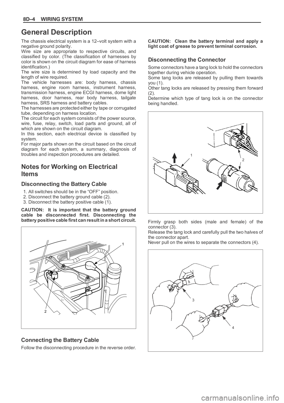
Disconnecting the Battery Cable
1. All switches should be in the “OFF” position.
2. Disconnect the battery ground cable (2).
3. Disconnect the battery positive cable (1).
CAUTION: It is important that the battery ground
cable be disconnected first. Disconnecting the
battery positive cable first can result in a short circuit.
Connecting the Battery Cable
Follow the disconnecting procedure in the reverse order.CAUTION: Clean the battery terminal and apply a
light coat of grease to prevent terminal corrosion.
Disconnecting the Connector
Some connectors have a tang lock to hold the connectors
together during vehicle operation.
Some tang locks are released by pulling them towards
you (1).
Other tang locks are released by pressing them forward
(2).
Determine which type of tang lock is on the connector
being handled.
Firmly grasp both sides (male and female) of the
connector (3).
Release the tang lock and carefully pull the two halves of
the connector apart.
Never pull on the wires to separate the connectors (4).
2
1
General Description
1
2
3
4
Page 2605 of 6000
Parts for Electrical Circuit
Wiring – Wire color
All wires have color–coded insulation.
Wires belonging to a system’s main harness will have a
single color (1). Wires belonging to a system’s subcircuits
will have a colored stripe (2). Striped wires use the
following code to show wire size and colors.
Example: 0.5 G / R
Red (Stripe color)
Green (Base color)
Wire size (0.5 mm
2)
Wiring – Wire Color Coding
Abbreviations are used to indicate wire color within a circuit diagram.
Refer to the following table.
Color Coding Meaning Color Coding Meaning
B Black BR Brown
W White LG Light green
RRedGRGrey
G Green P Pink
Y Yellow LB Light blue
LBlue VViolet
OOrange
1
2
Page 2610 of 6000
Relay Specifications and Configurations
* Relay contact shown in the wiring diagram indicates condition before actuation.
Page 2613 of 6000

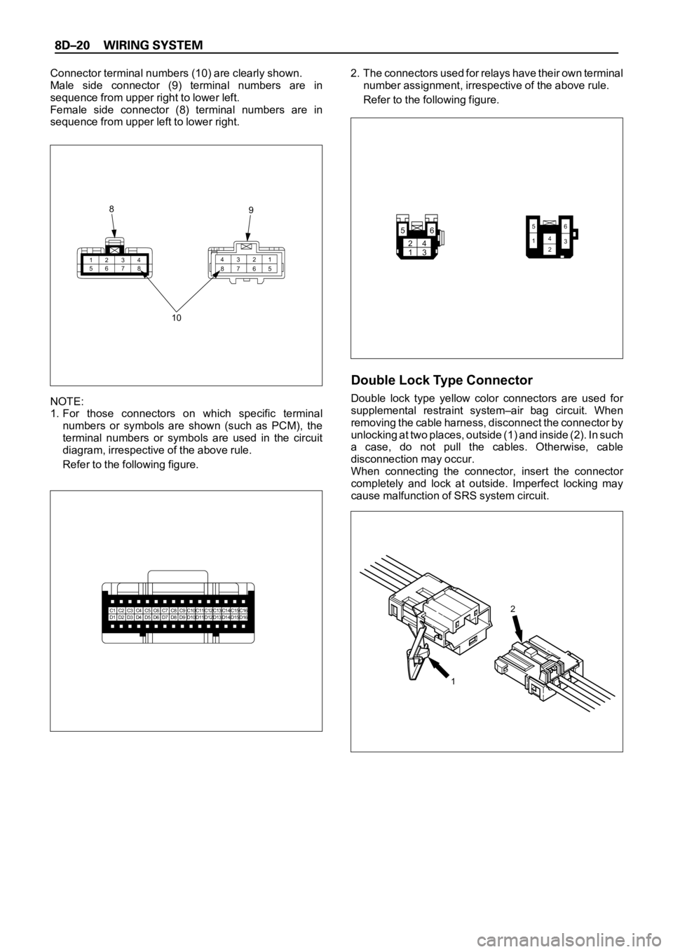
Connector terminal numbers (10) are clearly shown.
Male side connector (9) terminal numbers are in
sequence from upper right to lower left.
Female side connector (8) terminal numbers are in
sequence from upper left to lower right.
NOTE:
1. For those connectors on which specific terminal
numbers or symbols are shown (such as PCM), the
terminal numbers or symbols are used in the circuit
diagram, irrespective of the above rule.
Refer to the following figure.2. The connectors used for relays have their own terminal
number assignment, irrespective of the above rule.
Refer to the following figure.
Double Lock Type Connector
Double lock type yellow color connectors are used for
supplemental restraint system–air bag circuit. When
removing the cable harness, disconnect the connector by
unlocking at two places, outside (1) and inside (2). In such
a case, do not pull the cables. Otherwise, cable
disconnection may occur.
When connecting the connector, insert the connector
completely and lock at outside. Imperfect locking may
cause malfunction of SRS system circuit.
1234
56781 2 3 4
5 6 7 8
10 8
9
C1C2C3C4C5C6C7C8C9C10C11C12C13C14C15C16D1D2D3D4D5D6D7D8D9D10D11D12D13D14D15D162
1
24
136 5
65
1423
Page 2614 of 6000
Reading the Circuit Diagram
In this section, each system has its own parts location
illustration and circuit diagram.
And harness connector faces used in the circuit diagram
are shown at the end of this section.
Parts Location
The parts location shows the location of the connectors
(1) and the harness (2) used in each harness routing.
12
D08RWB11
Page 2615 of 6000
Circuit Diagram
The circuit diagram shows the power supply (1), the load
or loads (2) and the grounding point(s) (3).
5.0
W BATT.(+)
C-17 15A
RR DEF
RR DEFOGGER RELAY
3.0
L/O
3.0
B/L
3.0
B/L
3.0
B/L
B-38
4
I-17
5I-17
ILLUMINATION
CONTROLLER(3)
RR DEFOGGER
SW
RR DEFOGGER
2
H-37
G-7
1 2
B-38
2
2
H-31
1
G-3
3.0
B/Y
0.5
L/W
0.5
L/W
0.5
L/W 0.5
O/L
0.5
O/L STARTER SW
(IG1)
C-4 10A
ELEC.IGN.
3
B-38
4
I-17
15
H-48TIMER6
I-17 0.85
G/R TAIL RELAY(4)
B-38
1
H-253
H-255
1
I-17
B-2 2.0
B 3.0
B 3.0
B
2.0
B 0.3
B0.3
R/G
BODY-RHR-3
BODY-RR4
H-37
1
2
3
D08RW425
Page 2747 of 6000
Circuit Diagram
3.0
B/Y
0.5
L/W
0.5
L/W
HEADLIGHT
LEVELING
SWITCH
HEADLIGHT LEVELING
ACTUATOR-RH
0.85
L/W
0.5
P/L
0.5
P/L0.5
O/L
0.5
O/L0.5
L/O
0.5
L/O0.5
O/B
0.5
O/B STARTER SW
(IG1)
C-4 10A
ELEC. IG
I-30
6 20
1
C-763I-30
12
H-24
6
C-16
6 C-766 C-77
FENDER-LH
7
A
D
C-762
C
C-761
B
C-765 0.5
L/W0.5
P/L0.5
O/L0.5
L/O0.5
O/B
0.5
B 0.5
B
A
C-764
HEADLIGHT LEVELING
ACTUATOR-LH
C-773C-772C-771C-775 0.5
L/W0.5
L/W
0.85
L/W
0.5
P/L0.5
O/L0.5
L/O0.5
O/BC-774
H-127
I-30
2
3
H-24
B
I-30
3
13
H-9
C
I-30
4
11
H-9
D
H-25
0.85
G/R
0.3
R/G
I-30
7 9
I-30 TA I L
RELAY(4)
ILLUMINATION
CONTROLLER(3)
C-16
FENDER-LH
D08RW998