1998 OPEL FRONTERA diagram
[x] Cancel search: diagramPage 3358 of 6000
SECURITY AND LOCKS8H–19
Key
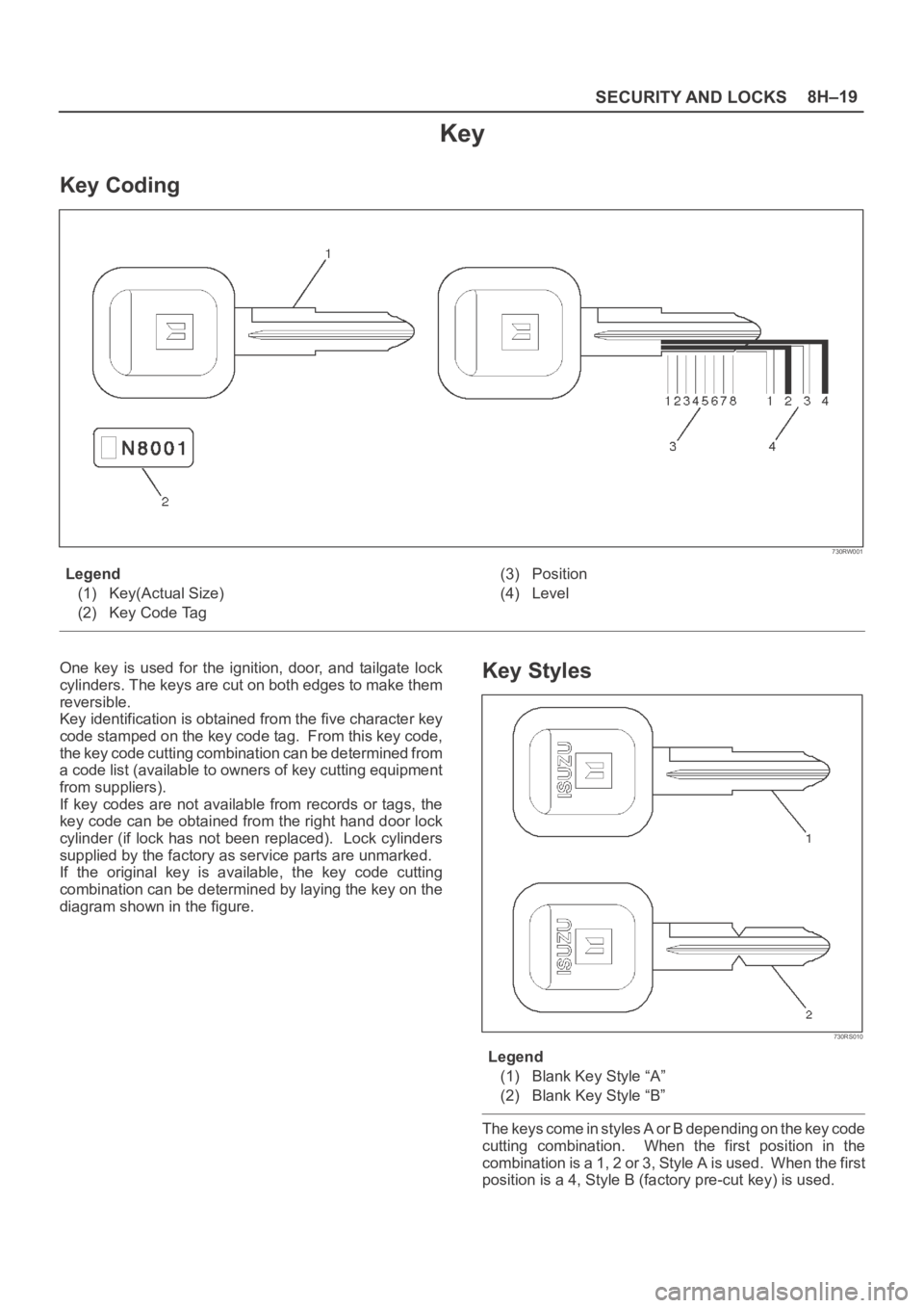
Key Coding
730RW001
Legend
(1) Key(Actual Size)
(2) Key Code Tag(3) Position
(4) Level
One key is used for the ignition, door, and tailgate lock
cylinders. The keys are cut on both edges to make them
reversible.
Key identification is obtained from the five character key
code stamped on the key code tag. From this key code,
the key code cutting combination can be determined from
a code list (available to owners of key cutting equipment
from suppliers).
If key codes are not available from records or tags, the
key code can be obtained from the right hand door lock
cylinder (if lock has not been replaced). Lock cylinders
supplied by the factory as service parts are unmarked.
If the original key is available, the key code cutting
combination can be determined by laying the key on the
diagram shown in the figure.Key Styles
730RS010
Legend
(1) Blank Key Style “A”
(2) Blank Key Style “B”
The keys come in styles A or B depending on the key code
cutting combination. When the first position in the
combination is a 1, 2 or 3, Style A is used. When the first
position is a 4, Style B (factory pre-cut key) is used.
Page 3489 of 6000
RESTRAINT CONTROL SYSTEM 9J1–2
Diagnostic Information
CAUTION: When fasteners are removed, always
reinstall them at the same location from which they
were removed. if a fastener needs to be replaced, use
the correct part number fastener for that application.
if the correct part number fastener is not available, a
fastener of equal size and strength (or stronger) may
be used. fasteners that are not reused, and those
requiring thread locking compound will be called
out. the correct torque value must be used when
installing fasteners that require it. if the above
conditions are not followed, parts or system damage
could result.
Diagnostic Procedures
WARNING: TO AVOID DEPLOYMENT WHEN
TROUBLESHOOTING THE SRS, DO NOT USE
ELECTRICAL TEST EQUIPMENT SUCH AS A
BATTERY–POWERED OR AC–POWERED
VOLTMETER, OHMMETER, ETC., OR ANY TYPE OF
ELECTRICAL EQUIPMENT OTHER THAN THAT
SPECIFIED IN THIS MANUAL. DO NOT USE A NON
POWERED, PROBE–TYPE TESTER.
INSTRUCTIONS IN THIS MANUAL MUST BE
FOLLOWED CAREFULLY, OTHERWISE PERSONAL
INJURY MAY RESULT.
The diagnostic procedures used in this section are
designed to aid in finding and repairing SRS problems.
Outlined below are the steps to find and repair SRS
problems quickly and effectively. Failure to carefully
follow these procedures may result in extended
diagnostic time, incorrect diagnosis and incorrect parts
replacement.
1.Perform The “SRS Diagnostic System Check”.
The “SRS Diagnostic System Check” should always
be the starting point of any SRS diagnostics. The
“SRS Diagnostic System Check” checks for proper
“AIR BAG” warning lamp operation and checks for
SRS trouble codes using both “Flash Code” and
“Scan Tool” Methods.
2.Refer To The Proper Diagnostic Chart As Directed
By The “SRS Diagnostic System Check”.
The “SRS Diagnostic System Check” will lead you to
the correct chart to diagnose any SRS problems.
Bypassing these procedures may result in extended
diagnostic time, incorrect diagnosis and incorrect
parts replacement.
3.Repeat The “SRS Diagnostic System Check”
After Any Repair Or Diagnostic Procedures Have
Been Performed.
Preforming the “SRS Diagnostic System Check” after
all repair or diagnostic procedures will assure that the
repair has been made correctly and that no other
conditions exist.
Diagnostic Codes
The Sensing and Diagnostic Module (SDM) maintains a
history record of all diagnostic codes that have beendetected since the SRS codes were last cleared during
service.
1. Active Codes — Faults that are presently detected
this ignition cycle. Active codes are stored in RAM
(Random Access Memory).
2. History Codes — All faults detected since the last
time the history fault memory was cleared. History
codes are stored in EEPROM. (Electronically
Erasable Programmable Read only Memory)
How To Read Trouble Codes
All codes (Active and history) can be read (or cleared) by
using a scan tool or equivalent.
If a PDT is not available, have the vehicle serviced by
ISUZU dealer.
How To Clear Trouble Codes
Trouble codes can only be cleared by using a Scan Tool.
If a “scan tool” is not available then inform the owner of the
stored codes and suggest that the codes are cleared
upon the next visit to an Isuzu dealership.
Scan Tool Diagnostics
A scan tool can be used to read current and history codes
and to clear all history codes after a repair is complete.
The scan tool must be updated to communicate with the
SRS through a memory card or a manufacturer’s update
before it can be used for SRS diagnostics. To use the
scan tool, connect it to the DLC connector and turn the
ignition switch “ON”. Then follow the manufacturer’s
directions for communication with the SRS. The scan tool
reads serial data from the SDM “Serial Data” output
(terminal 24) to the DLC connector (terminal 9).
Basic Knowledge Required
Before using this section of the Service Manual, there is
some basic knowledge which will be required. Without
this knowledge, you will have trouble using the diagnostic
procedures in this section. Use care to prevent harm or
unwanted deployment. Read all cautions in the service
manual and on warning labels attached to SRS
components.
Basic Electrical Circuits
You should understand the basic theory of electricity
including series and parallel circuits, and understand the
voltage drops across series resistors. You should know
the meaning of voltage (volts), current (amps), and
resistance (ohms). You should understand what happens
in a circuit with an open or a shorted wire. You should be
able to read and understand a wiring diagram.
“Flash Code” Diagnostics
Flash code diagnostics can be used to read active codes
and to determine if history codes are present but cannot
be used to clear codes or read history codes. Flash code
diagnostics is enabled by grounding by terminal 4
shorting to terminal 13 of the DLC connector with the
ignition switch “ON”. Grounding terminal 4 of the DLC
connector pulls the “Diagnostics Request” input (Terminal
1) of the SDM low and signals the SDM to enter the flash
code diagnostic display mode.
Page 3552 of 6000
10A–1
CRUISE CONTROL SYSTEM
CONTROL SYSTEM
CRUISE CONTROL SYSTEM
CONTENTS
Service Precaution 10A–1. . . . . . . . . . . . . . . . . . . . . .
General Description 10A–1. . . . . . . . . . . . . . . . . . . . .
Diagnosis 10A–2. . . . . . . . . . . . . . . . . . . . . . . . . . . . . .
Brake Switch 10A–2. . . . . . . . . . . . . . . . . . . . . . . . . . .
Removal 10A–2. . . . . . . . . . . . . . . . . . . . . . . . . . . . .
Installation 10A–2. . . . . . . . . . . . . . . . . . . . . . . . . . . .
Adjustment 10A–3. . . . . . . . . . . . . . . . . . . . . . . . . . .
Clutch Switch 10A–3. . . . . . . . . . . . . . . . . . . . . . . . . . .
Removal and Installation 10A–3. . . . . . . . . . . . . . .
Adjustment 10A–3. . . . . . . . . . . . . . . . . . . . . . . . . . .
Starter Switch 10A–4. . . . . . . . . . . . . . . . . . . . . . . . . . .
Removal 10A–4. . . . . . . . . . . . . . . . . . . . . . . . . . . . .
Installation 10A–4. . . . . . . . . . . . . . . . . . . . . . . . . . . .
Cruise Control Main Switch 10A–5. . . . . . . . . . . . . . . Removal 10A–5. . . . . . . . . . . . . . . . . . . . . . . . . . . . .
Installation 10A–5. . . . . . . . . . . . . . . . . . . . . . . . . . . .
Cruise Control Switch (Combination Switch) 10A–5
Removal and Installation 10A–5. . . . . . . . . . . . . . .
Cruise Control Unit 10A–6. . . . . . . . . . . . . . . . . . . . . .
Removal 10A–6. . . . . . . . . . . . . . . . . . . . . . . . . . . . .
Installation 10A–6. . . . . . . . . . . . . . . . . . . . . . . . . . . .
Cruise Actuator 10A–7. . . . . . . . . . . . . . . . . . . . . . . . .
Actuator Cable Diagram (LHD) 10A–7. . . . . . . . . .
Actuator Cable Diagram (RHD) 10A–7. . . . . . . . . .
Removal 10A–8. . . . . . . . . . . . . . . . . . . . . . . . . . . . .
Installation 10A–8. . . . . . . . . . . . . . . . . . . . . . . . . . . .
Mode Switch 10A–8. . . . . . . . . . . . . . . . . . . . . . . . . . . .
Removal and Installation 10A–8. . . . . . . . . . . . . . .
Service Precaution
WARNING: IF SO EQUIPPED WITH A
SUPPLEMENTAL RESTRAINT SYSTEM (SRS),
REFER TO THE SRS COMPONENT AND WIRING
LOCATION VIEW IN ORDER TO DETERMINE
WHETHER YOU ARE PERFORMING SERVICE ON OR
NEAR THE SRS COMPONENTS OR THE SRS
WIRING. WHEN YOU ARE PERFORMING SERVICE
ON OR NEAR THE SRS COMPONENTS OR THE SRS
WIRING, REFER TO THE SRS SERVICE
INFORMATION. FAILURE TO FOLLOW WARNINGS
COULD RESULT IN POSSIBLE AIR BAG
DEPLOYMENT, PERSONAL INJURY, OR
OTHERWISE UNNEEDED SRS SYSTEM REPAIRS.
CAUTION: Always use the correct fastener in the
proper location. When you replace a fastener, use
ONLY the exact part number for that application.
ISUZU will call out those fasteners that require a
replacement after removal. ISUZU will also call out
the fasteners that require thread lockers or thread
sealant. UNLESS OTHERWISE SPECIFIED, do not
use supplemental coatings (Paints, greases, or other
corrosion inhibitors) on threaded fasteners or
fastener joint interfaces. Generally, such coatings
adversely affect the fastener torque and the joint
clamping force, and may damage the fastener. When
you install fasteners, use the correct tightening
sequence and specifications. Following these
instructions can help you avoid damage to parts and
systems.
General Description
The cruise control keeps the vehicle running at a fixed
speed until a signal canceling this fixed speed is received .
When the main switch “AUTO CRUISE” is turned on with
the vehicle in the running mode, the battery voltage is
applied to the control unit. When a signal from the control
switch is input to the control unit while the vehicle is in this
state, the cruise control actuator is activated to operate
the system. Also, while the system is operating, the
“AUTO CRUISE” indicator light in the meter assembly
lights up.
1. SET/COAST Switch Function
1.Set Function: When the SET/COAST switch is
pressed and released with the main switch on, the
speed at which the vehicle is running at that moment
is stored in the memory, and the vehicle automatically
runs at the stored speed.
2.Coast-down Function: When the SET/COAST
switch is kept on while the vehicle in running, the
vehicle decelerates during that time. The speed at
which vehicle is running when the control switch is
turned off is stored in the memory, and the vehicle
automatically returns to the stored speed.
3.Tap-down Function: When the SET/COAST switch
is turned on and off instantaneously while the vehicle
is running, the vehicle decelerates a mile for each
on/off operation. The vehicle speed at which the
vehicle was running when the SET/COAST was
turned off last is stored in the memory, and the vehicle
automatically returns to this stored speed.
Page 3558 of 6000
10A–7
CRUISE CONTROL SYSTEM
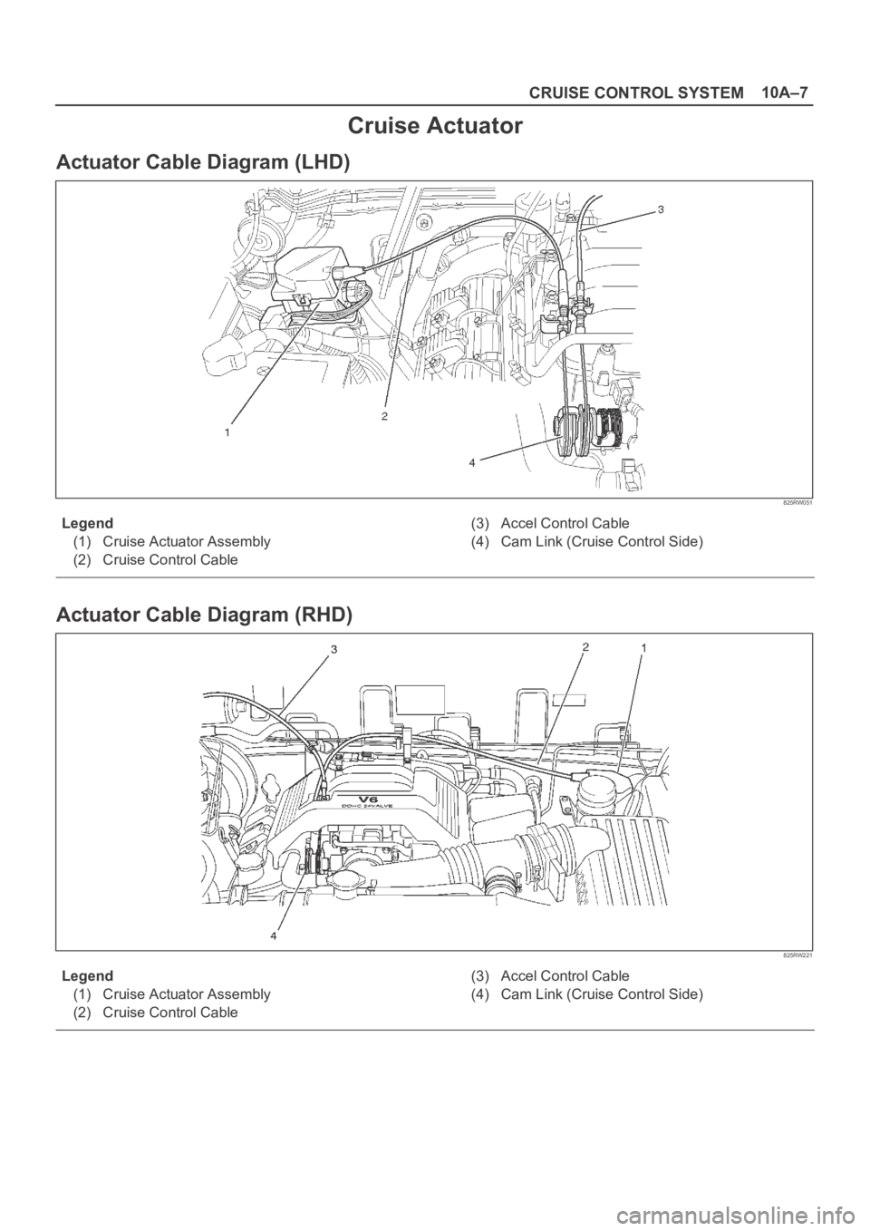
Cruise Actuator
Actuator Cable Diagram (LHD)
825RW051
Legend
(1) Cruise Actuator Assembly
(2) Cruise Control Cable(3) Accel Control Cable
(4) Cam Link (Cruise Control Side)
Actuator Cable Diagram (RHD)
825RW221
Legend
(1) Cruise Actuator Assembly
(2) Cruise Control Cable(3) Accel Control Cable
(4) Cam Link (Cruise Control Side)
Page 4046 of 6000
4B1–1 DRIVE LINE CONTROL SYSTEM (SHIFT ON THE FLY)
DRIVELINE/AXLE
DRIVELINE CONTROL SYSTEM (SHIFT ON THE FLY)
CONTENTS
Service Precaution 4B1–1. . . . . . . . . . . . . . . . . . . . . .
Shift on the Fly System (Lever Type) 4B1–2. . . . . . .
Outline of Shift on the Fly System
(Lever Type) 4B1–2. . . . . . . . . . . . . . . . . . . . . . . . . . .
Shift on the Fly Vacuum Piping and Electric
Equipment (For Lever Control Type) 4B1–3. . . . . .
Vacuum Piping Diagram 4B1–3. . . . . . . . . . . . . . . .
Inspection and Repair 4B1–4. . . . . . . . . . . . . . . . . .
Shift on the Fly System (Push Button Type) 4B1–7.
Outline of Shift on the Fly System
(Push Button Type) 4B1–7. . . . . . . . . . . . . . . . . . . . Functions of Indicator Lamp 4B1–11. . . . . . . . . . . . . . .
Diagnosis 4B1–11. . . . . . . . . . . . . . . . . . . . . . . . . . . . .
Front Axle Diagnosis 4B1–30. . . . . . . . . . . . . . . . . . .
Shift on the Fly Vacuum Piping and Electric
Equipment (For Push Button Type) 4B1–32. . . . . . . .
Vacuum Piping Diagram 4B1–32. . . . . . . . . . . . . . . .
Inspection and Repair 4B1–33. . . . . . . . . . . . . . . . . .
4WD Control Unit (For Push Button Type) 4B1–36. .
4WD Control Unit Associated Parts 4B1–36. . . . . .
Removal 4B1–37. . . . . . . . . . . . . . . . . . . . . . . . . . . . .
Installation 4B1–37. . . . . . . . . . . . . . . . . . . . . . . . . . . .
Service Precaution
WARNING: IF SO EQUIPPED WITH A
SUPPLEMENTAL RESTRAINT SYSTEM (SRS),
REFER TO THE SRS COMPONENT AND WIRING
LOCATION VIEW IN ORDER TO DETERMINE
WHETHER YOU ARE PERFORMING SERVICE ON OR
NEAR THE SRS COMPONENTS OR THE SRS
WIRING. WHEN YOU ARE PERFORMING SERVICE
ON OR NEAR THE SRS COMPONENTS OR THE SRS
WIRING, REFER TO THE SRS SERVICE
INFORMATION. FAILURE TO FOLLOW WARNINGS
COULD RESULT IN POSSIBLE AIR BAG
DEPLOYMENT, PERSONAL INJURY, OR
OTHERWISE UNNEEDED SRS SYSTEM REPAIRS.
CAUTION: Always use the correct fastener in the
proper location. When you replace a fastener, use
ONLY the exact part number for that application.
ISUZU will call out those fasteners that require a
replacement after removal. ISUZU will also call out
the fasteners that require thread lockers or thread
sealant. UNLESS OTHERWISE SPECIFIED, do not
use supplemental coatings (Paints, greases, or other
corrosion inhibitors) on threaded fasteners or
fastener joint interfaces. Generally, such coatings
adversely affect the fastener torque and the joint
clamping force, and may damage the fastener. When
you install fasteners, use the correct tightening
sequence and specifications. Following these
instructions can help you avoid damage to parts and
systems.
Page 4048 of 6000
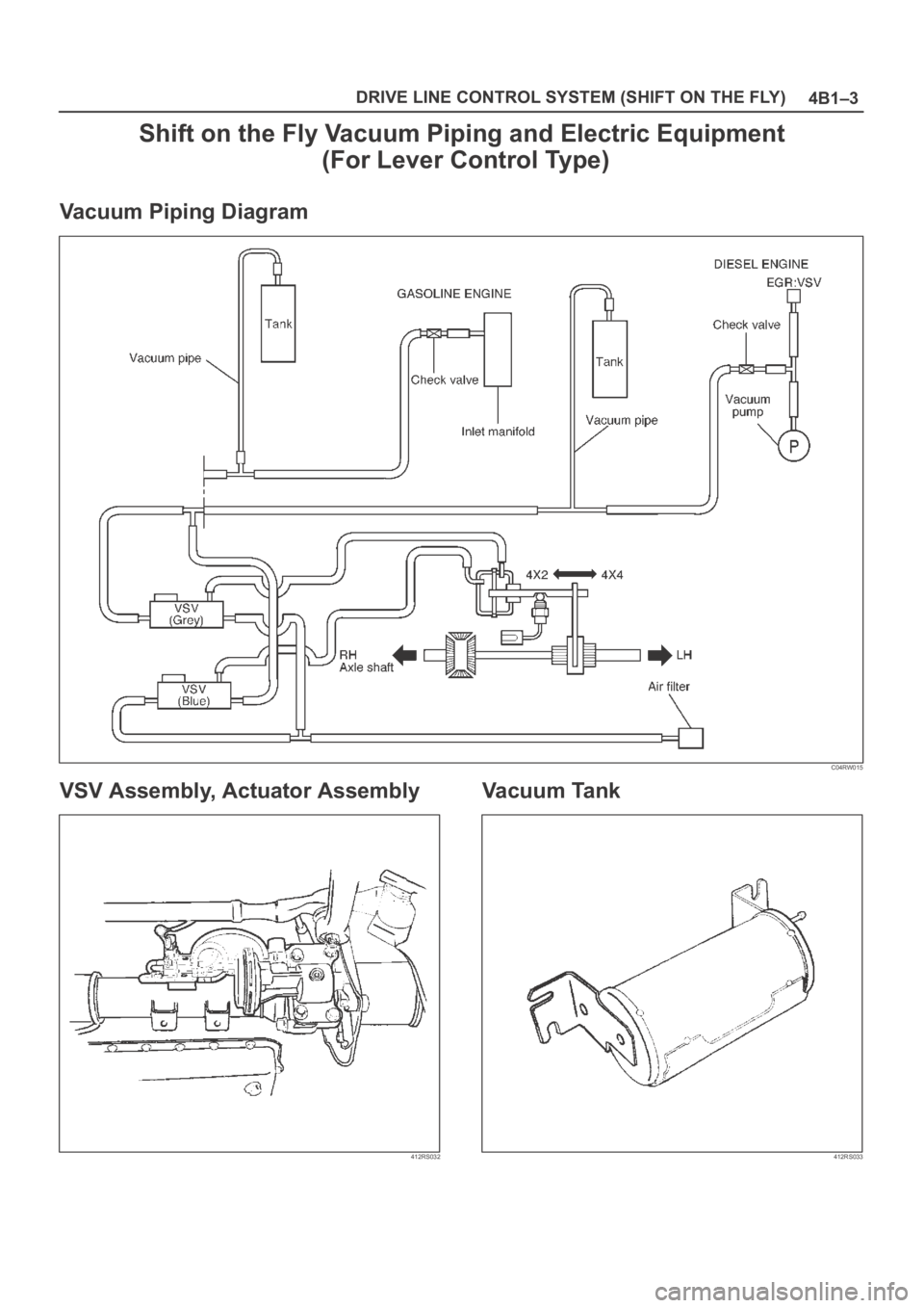
4B1–3 DRIVE LINE CONTROL SYSTEM (SHIFT ON THE FLY)
Shift on the Fly Vacuum Piping and Electric Equipment
(For Lever Control Type)
Vacuum Piping Diagram
C04RW015
VSV Assembly, Actuator Assembly
412RS032
Vacuum Tank
412RS033
Page 4052 of 6000
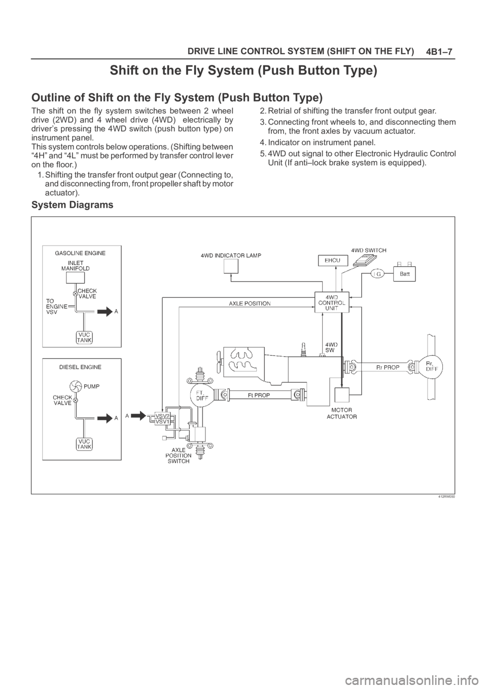
4B1–7 DRIVE LINE CONTROL SYSTEM (SHIFT ON THE FLY)
Shift on the Fly System (Push Button Type)
Outline of Shift on the Fly System (Push Button Type)
The shift on the fly system switches between 2 wheel
drive (2WD) and 4 wheel drive (4WD) electrically by
driver’s pressing the 4WD switch (push button type) on
instrument panel.
This system controls below operations. (Shifting between
“4H” and “4L” must be performed by transfer control lever
on the floor.)
1. Shifting the transfer front output gear (Connecting to,
and disconnecting from, front propeller shaft by motor
actuator).2. Retrial of shifting the transfer front output gear.
3. Connecting front wheels to, and disconnecting them
from, the front axles by vacuum actuator.
4. Indicator on instrument panel.
5. 4WD out signal to other Electronic Hydraulic Control
Unit (If anti–lock brake system is equipped).
System Diagrams
412RW050
Page 4061 of 6000
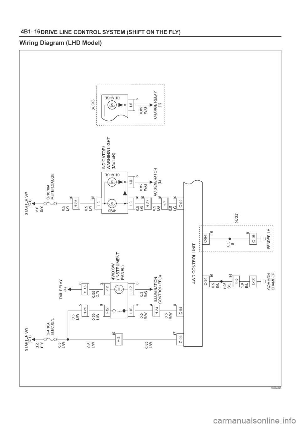
4B1–16
DRIVE LINE CONTROL SYSTEM (SHIFT ON THE FLY)
Wiring Diagram (LHD Model)
D08RW845