Page 4062 of 6000
4B1–17 DRIVE LINE CONTROL SYSTEM (SHIFT ON THE FLY)
Wiring Diagram (LHD / Diesel Engine Model)
D08RW841
Page 4063 of 6000
4B1–18
DRIVE LINE CONTROL SYSTEM (SHIFT ON THE FLY)
Wiring Diagram (LHD / Gasoline Engine Model)
D08RW843
Page 4064 of 6000
4B1–19 DRIVE LINE CONTROL SYSTEM (SHIFT ON THE FLY)
Wiring Diagram (RHD Model)
D08RW844
Page 4065 of 6000
4B1–20
DRIVE LINE CONTROL SYSTEM (SHIFT ON THE FLY)
Wiring Diagram (RHD / Diesel Engine Model)
D08RW842
Page 4066 of 6000
4B1–21 DRIVE LINE CONTROL SYSTEM (SHIFT ON THE FLY)
Wiring Diagram (RHD / Gasoline Engine Model)
D08RW638
Page 4077 of 6000
4B1–32
DRIVE LINE CONTROL SYSTEM (SHIFT ON THE FLY)
Shift on the Fly Vacuum Piping and Electric Equipment
(For Push Button Type)
Vacuum Piping Diagram
C04RW013
VSV Assembly, Actuator Assembly
412RS032
Vacuum Tank
412RS033
Page 4084 of 6000

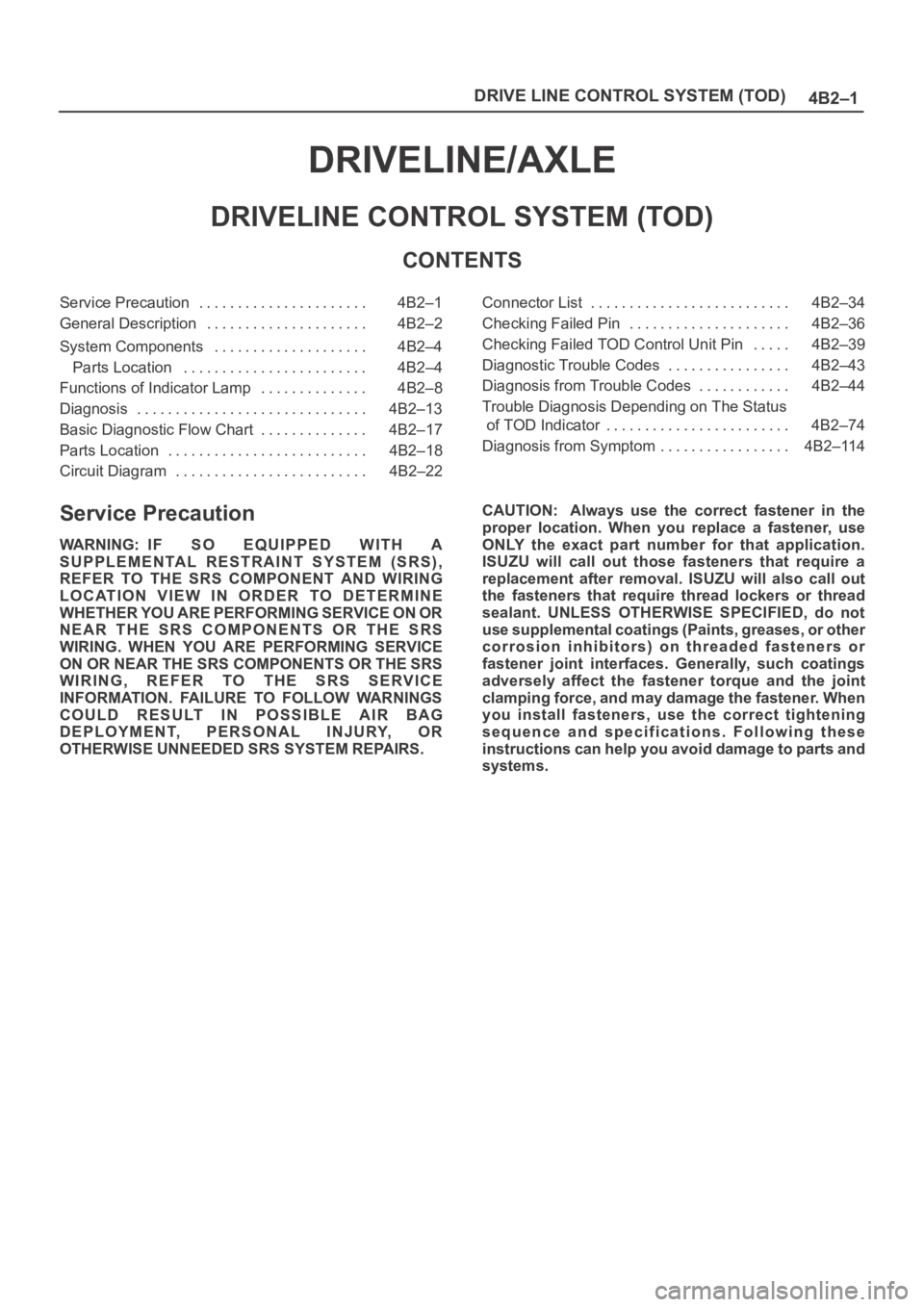
4B2–1 DRIVE LINE CONTROL SYSTEM (TOD)
DRIVELINE/AXLE
DRIVELINE CONTROL SYSTEM (TOD)
CONTENTS
Service Precaution 4B2–1. . . . . . . . . . . . . . . . . . . . . .
General Description 4B2–2. . . . . . . . . . . . . . . . . . . . .
System Components 4B2–4. . . . . . . . . . . . . . . . . . . .
Parts Location 4B2–4. . . . . . . . . . . . . . . . . . . . . . . .
Functions of Indicator Lamp 4B2–8. . . . . . . . . . . . . .
Diagnosis 4B2–13. . . . . . . . . . . . . . . . . . . . . . . . . . . . . .
Basic Diagnostic Flow Chart 4B2–17. . . . . . . . . . . . . .
Parts Location 4B2–18. . . . . . . . . . . . . . . . . . . . . . . . . .
Circuit Diagram 4B2–22. . . . . . . . . . . . . . . . . . . . . . . . . Connector List 4B2–34. . . . . . . . . . . . . . . . . . . . . . . . . .
Checking Failed Pin 4B2–36. . . . . . . . . . . . . . . . . . . . .
Checking Failed TOD Control Unit Pin 4B2–39. . . . .
Diagnostic Trouble Codes 4B2–43. . . . . . . . . . . . . . . .
Diagnosis from Trouble Codes 4B2–44. . . . . . . . . . . .
Trouble Diagnosis Depending on The Status
of TOD Indicator 4B2–74. . . . . . . . . . . . . . . . . . . . . . . .
Diagnosis from Symptom 4B2–114. . . . . . . . . . . . . . . . .
Service Precaution
WARNING: IF SO EQUIPPED WITH A
SUPPLEMENTAL RESTRAINT SYSTEM (SRS),
REFER TO THE SRS COMPONENT AND WIRING
LOCATION VIEW IN ORDER TO DETERMINE
WHETHER YOU ARE PERFORMING SERVICE ON OR
NEAR THE SRS COMPONENTS OR THE SRS
WIRING. WHEN YOU ARE PERFORMING SERVICE
ON OR NEAR THE SRS COMPONENTS OR THE SRS
WIRING, REFER TO THE SRS SERVICE
INFORMATION. FAILURE TO FOLLOW WARNINGS
COULD RESULT IN POSSIBLE AIR BAG
DEPLOYMENT, PERSONAL INJURY, OR
OTHERWISE UNNEEDED SRS SYSTEM REPAIRS.CAUTION: Always use the correct fastener in the
proper location. When you replace a fastener, use
ONLY the exact part number for that application.
ISUZU will call out those fasteners that require a
replacement after removal. ISUZU will also call out
the fasteners that require thread lockers or thread
sealant. UNLESS OTHERWISE SPECIFIED, do not
use supplemental coatings (Paints, greases, or other
corrosion inhibitors) on threaded fasteners or
fastener joint interfaces. Generally, such coatings
adversely affect the fastener torque and the joint
clamping force, and may damage the fastener. When
you install fasteners, use the correct tightening
sequence and specifications. Following these
instructions can help you avoid damage to parts and
systems.
Page 4105 of 6000
DRIVE LINE CONTROL SYSTEM (TOD) 4B2–22
Circuit Diagram–1 (RHD 6VE1)
D04RY00041