1998 NISSAN PICK-UP checking oil
[x] Cancel search: checking oilPage 1086 of 1659
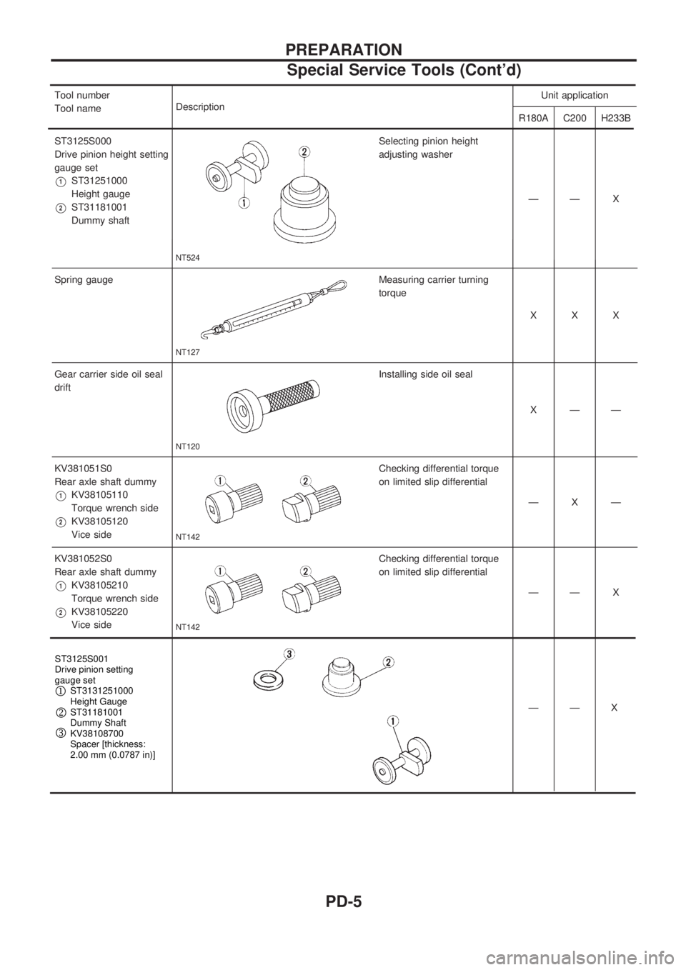
Tool number
Tool nameDescription Unit application
R180A C200 H233B
ST3125S000
Drive pinion height setting
gauge set
V1ST31251000
Height gauge
V2ST31181001
Dummy shaft
NT524
Selecting pinion height
adjusting washer
ÐÐ X
Spring gauge
NT127
Measuring carrier turning
torque XXX
Gear carrier side oil seal
drift
NT120
Installing side oil seal XÐÐ
KV381051S0
Rear axle shaft dummy
V1KV38105110
Torque wrench side
V2KV38105120
Vice side
NT142
Checking differential torque
on limited slip differential ÐXÐ
KV381052S0
Rearaxleshaftdummy
V1KV38105210
Torque wrench side
V2KV38105220
Vice side
NT142
Checking differential torque
on limited slip differential ÐÐX
——X
—X
PREPARATION
Special Service Tools (Cont'd)
PD-5
Page 1089 of 1659
On-vehicle Service
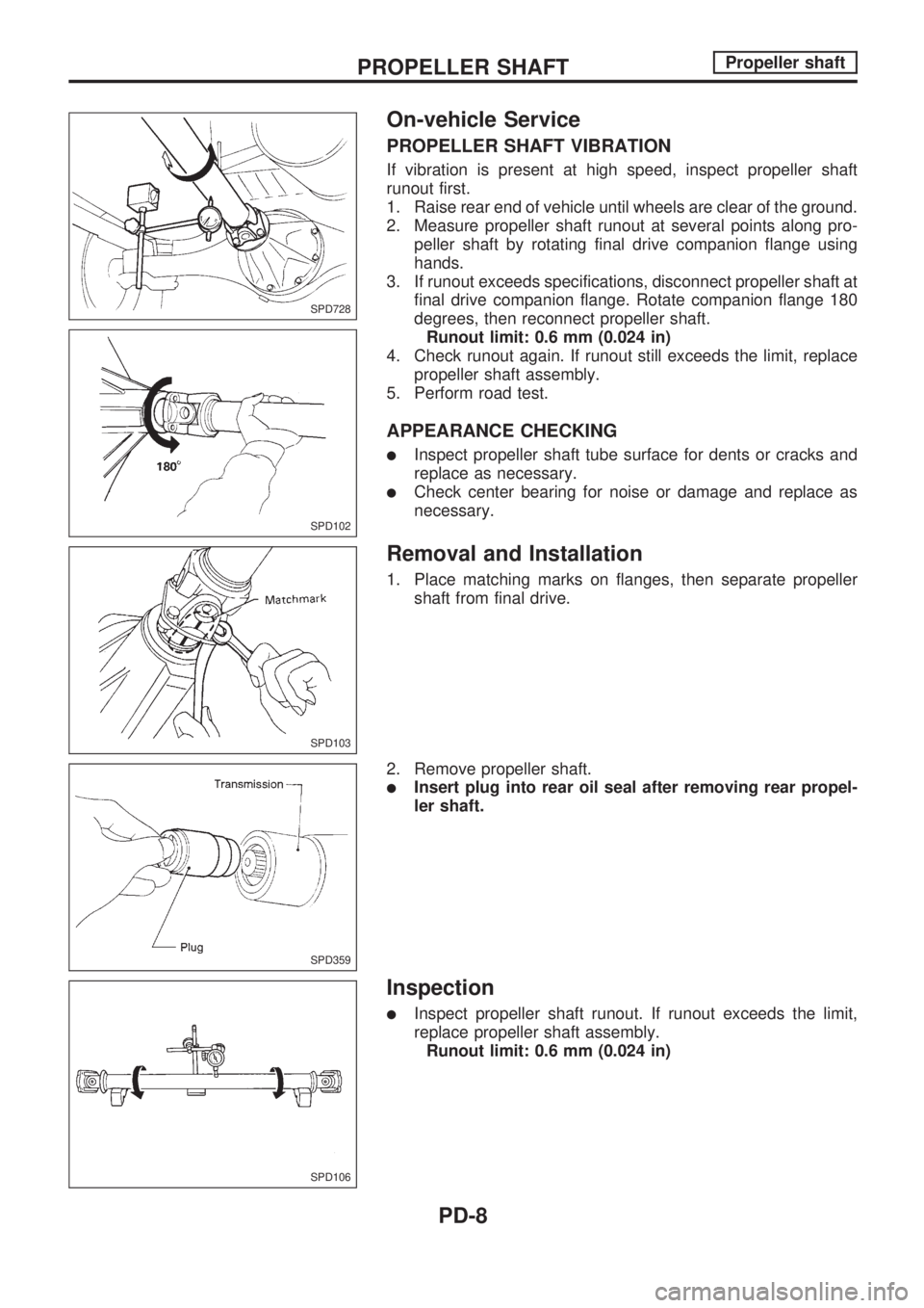
PROPELLER SHAFT VIBRATION
If vibration is present at high speed, inspect propeller shaft
runout first.
1. Raise rear end of vehicle until wheels are clear of the ground.
2. Measure propeller shaft runout at several points along pro-
peller shaft by rotating final drive companion flange using
hands.
3. If runout exceeds specifications, disconnect propeller shaft at
final drive companion flange. Rotate companion flange 180
degrees, then reconnect propeller shaft.
Runout limit: 0.6 mm (0.024 in)
4. Check runout again. If runout still exceeds the limit, replace
propeller shaft assembly.
5. Perform road test.
APPEARANCE CHECKING
lInspect propeller shaft tube surface for dents or cracks and
replace as necessary.
lCheck center bearing for noise or damage and replace as
necessary.
Removal and Installation
1. Place matching marks on flanges, then separate propeller
shaft from final drive.
2. Remove propeller shaft.
lInsert plug into rear oil seal after removing rear propel-
ler shaft.
Inspection
lInspect propeller shaft runout. If runout exceeds the limit,
replace propeller shaft assembly.
Runout limit: 0.6 mm (0.024 in)
SPD728
SPD102
SPD103
SPD359
SPD106
PROPELLER SHAFTPropeller shaft
PD-8
Page 1130 of 1659
Tooth Contact
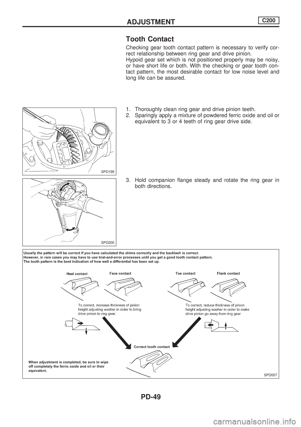
Checking gear tooth contact pattern is necessary to verify cor-
rect relationship between ring gear and drive pinion.
Hypoid gear set which is not positioned properly may be noisy,
or have short life or both. With the checking or gear tooth con-
tact pattern, the most desirable contact for low noise level and
long life can be assured.
1. Thoroughly clean ring gear and drive pinion teeth.
2. Sparingly apply a mixture of powdered ferric oxide and oil or
equivalent to 3 or 4 teeth of ring gear drive side.
3. Hold companion flange steady and rotate the ring gear in
both directions.
SPD199
SPD200
SPD007
ADJUSTMENTC200
PD-49
Page 1134 of 1659
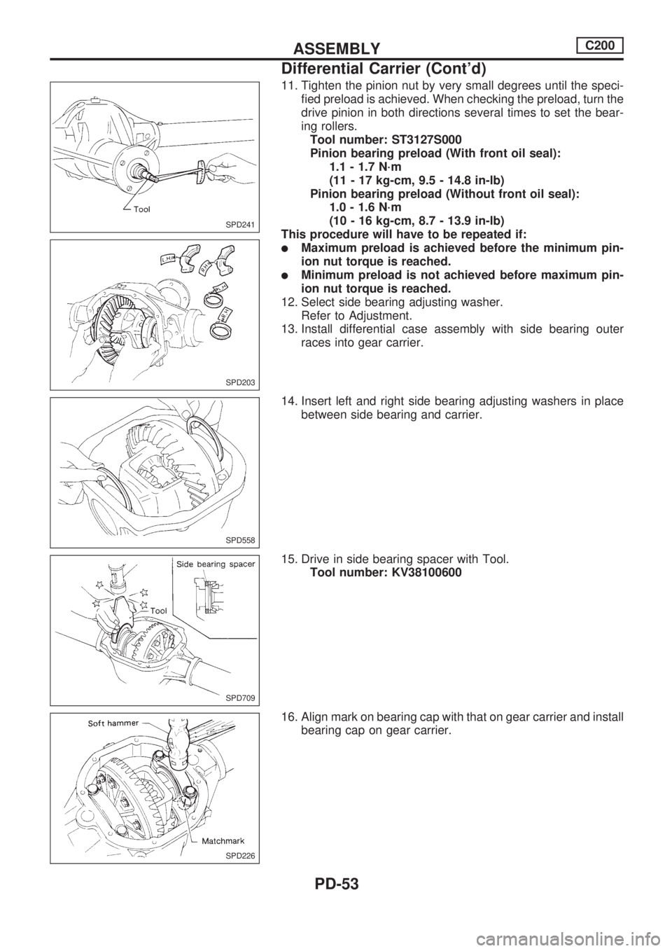
11. Tighten the pinion nut by very small degrees until the speci-
fied preload is achieved. When checking the preload, turn the
drive pinion in both directions several times to set the bear-
ing rollers.
Tool number: ST3127S000
Pinion bearing preload (With front oil seal):
1.1 - 1.7 N´m
(11 - 17 kg-cm, 9.5 - 14.8 in-lb)
Pinion bearing preload (Without front oil seal):
1.0 - 1.6 N´m
(10 - 16 kg-cm, 8.7 - 13.9 in-lb)
This procedure will have to be repeated if:
lMaximum preload is achieved before the minimum pin-
ion nut torque is reached.
lMinimum preload is not achieved before maximum pin-
ion nut torque is reached.
12. Select side bearing adjusting washer.
Refer to Adjustment.
13. Install differential case assembly with side bearing outer
races into gear carrier.
14. Insert left and right side bearing adjusting washers in place
between side bearing and carrier.
15. Drive in side bearing spacer with Tool.
Tool number: KV38100600
16. Align mark on bearing cap with that on gear carrier and install
bearing cap on gear carrier.
SPD241
SPD203
SPD558
SPD709
SPD226
ASSEMBLYC200
Differential Carrier (Cont'd)
PD-53
Page 1155 of 1659
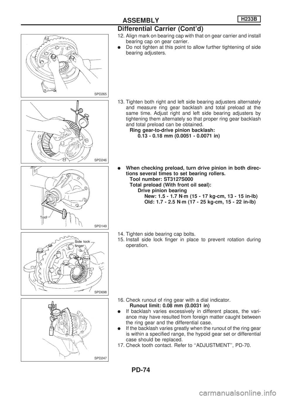
12. Align mark on bearing cap with that on gear carrier and install
bearing cap on gear carrier.
lDo not tighten at this point to allow further tightening of side
bearing adjusters.
13. Tighten both right and left side bearing adjusters alternately
and measure ring gear backlash and total preload at the
same time. Adjust right and left side bearing adjusters by
tightening them alternately so that proper ring gear backlash
and total preload can be obtained.
Ring gear-to-drive pinion backlash:
0.13 - 0.18 mm (0.0051 - 0.0071 in)
lWhen checking preload, turn drive pinion in both direc-
tions several times to set bearing rollers.
Tool number: ST3127S000
Total preload (With front oil seal):
Drive pinion bearing
New: 1.5 - 1.7 N´m (15 - 17 kg-cm, 13 - 15 in-lb)
Old: 1.7 - 2.5 N´m (17 - 25 kg-cm, 15 - 22 in-lb)
14. Tighten side bearing cap bolts.
15. Install side lock finger in place to prevent rotation during
operation.
16. Check runout of ring gear with a dial indicator.
Runout limit: 0.08 mm (0.0031 in)
lIf backlash varies excessively in different places, the vari-
ance may have resulted from foreign matter caught between
the ring gear and the differential case.
lIf the backlash varies greatly when the runout of the ring gear
is within a specified range, the hypoid gear set or differential
case should be replaced.
17. Check tooth contact. Refer to ``ADJUSTMENT'', PD-70.
SPD265
SPD246
SPD149
SPD698
SPD247
ASSEMBLYH233B
Differential Carrier (Cont'd)
PD-74
Page 1222 of 1659
STEERING SYSTEM
SECTIONST
CONTENTS
PRECAUTIONS AND PREPARATION..................... 1
Supplemental Restraint System (SRS) ``AIR
BAG'' (4WD models).............................................. 1
Supplemental Restraint System (SRS) ``AIR
BAG'' (2WD models).............................................. 1
Precautions for Steering System ........................... 1
Special Service Tools ............................................ 2
ON-VEHICLE SERVICE............................................ 4
Steering System..................................................... 4
Checking and Adjusting Drive Belts (For
power steering) ...................................................... 4
Checking Fluid Level (For power steering) ........... 4
Checking Fluid Leakage (For power steering) ...... 5
Bleeding Hydraulic System (For power
steering) ................................................................. 5
Checking Steering Wheel Turning Force (For
power steering) ...................................................... 6
Checking Steering Wheel Play .............................. 6
Checking Neutral Position on Steering Wheel ...... 7
Checking Front Wheel Turning Angle ................... 7
Checking Hydraulic System (For power
steering) ................................................................. 7
STEERING WHEEL AND STEERING COLUMN..... 9
Steering Wheel ...................................................... 9
Steering Column .................................................. 10
Disassembly and Assembly ................................. 11
Inspection ............................................................. 12
MANUAL STEERING GEAR (Model: VB66K)....... 13
Removal and Installation ..................................... 13
Disassembly ......................................................... 14
Assembly and Adjustment ................................... 14Inspection ............................................................. 17
POWER STEERING SYSTEM (Model: PB48S)..... 19
Description ........................................................... 19
POWER STEERING GEAR (Model: PB48S)......... 20
Removal and Installation ..................................... 20
Power Steering Gear Component ....................... 20
Pre-disassembly Inspection and Adjustment....... 21
Disassembly ......................................................... 22
Assembly.............................................................. 24
POWER STEERING SYSTEM (Model: PB59K).... 27
Description ........................................................... 27
POWER STEERING GEAR (Model: PB59K)......... 28
Removal and Installation ..................................... 28
Power Steering Gear Component ....................... 28
Pre-disassembly Inspection and Adjustment....... 29
Disassembly ......................................................... 30
Assembly.............................................................. 31
POWER STEERING OIL PUMP.............................. 34
Disassembly and Assembly ................................. 34
Pre-disassembly Inspection ................................. 34
Inspection ............................................................. 35
Disassembly ......................................................... 35
Assembly.............................................................. 36
STEERING LINKAGE.............................................. 37
Removal and Installation ..................................... 37
Disassembly ......................................................... 38
Inspection ............................................................. 39
SERVICE DATA AND SPECIFICATIONS (SDS)... 40
General Specifications ......................................... 40
Inspection and Adjustment .................................. 40
ST
Page 1229 of 1659
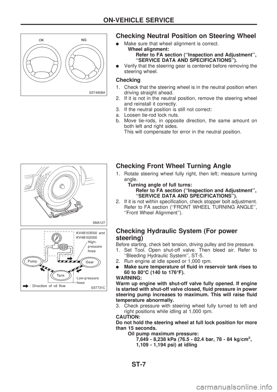
Checking Neutral Position on Steering Wheel
lMake sure that wheel alignment is correct.
Wheel alignment:
Refer to FA section (``Inspection and Adjustment'',
``SERVICE DATA AND SPECIFICATIONS'').
lVerify that the steering gear is centered before removing the
steering wheel.
Checking
1. Check that the steering wheel is in the neutral position when
driving straight ahead.
2. If it is not in the neutral position, remove the steering wheel
and reinstall it correctly.
3. If the neutral position is still not correct:
a. Loosen tie-rod lock nuts.
b. Move tie-rods, in opposite direction, the same amount on
both left and right sides.
This will compensate for error in the neutral position.
Checking Front Wheel Turning Angle
1. Rotate steering wheel fully right, then left; measure turning
angle.
Turning angle of full turns:
Refer to FA section (``Inspection and Adjustment'',
``SERVICE DATA AND SPECIFICATIONS'').
2. If it is not within specification, check stopper bolt adjustment.
Refer to FA section (``FRONT WHEEL TURNING ANGLE'',
``Front Wheel Alignment'').
Checking Hydraulic System (For power
steering)
Before starting, check belt tension, driving pulley and tire pressure.
1. Set Tool. Open shut-off valve. Then bleed air. Refer to
``Bleeding Hydraulic System'', ST-5.
2. Run engine at idle speed or 1,000 rpm.
lMake sure temperature of fluid in reservoir tank rises to
60 to 80ÉC (140 to 176ÉF).
WARNING:
Warm up engine with shut-off valve fully opened. If engine
is started with shut-off valve closed, fluid pressure in power
steering pump increases to maximum. This will raise fluid
temperature abnormally.
3. Check pressure with steering wheel fully turned to left and
right positions while idling at 1,000 rpm.
CAUTION:
Do not hold the steering wheel at full lock position for more
than 15 seconds.
Oil pump maximum pressure:
7,649 - 8,238 kPa (76.5 - 82.4 bar, 78 - 84 kg/cm
2,
1,109 - 1,194 psi) at idling
SST490BA
SMA127
SST731C
ON-VEHICLE SERVICE
ST-7
Page 1558 of 1659
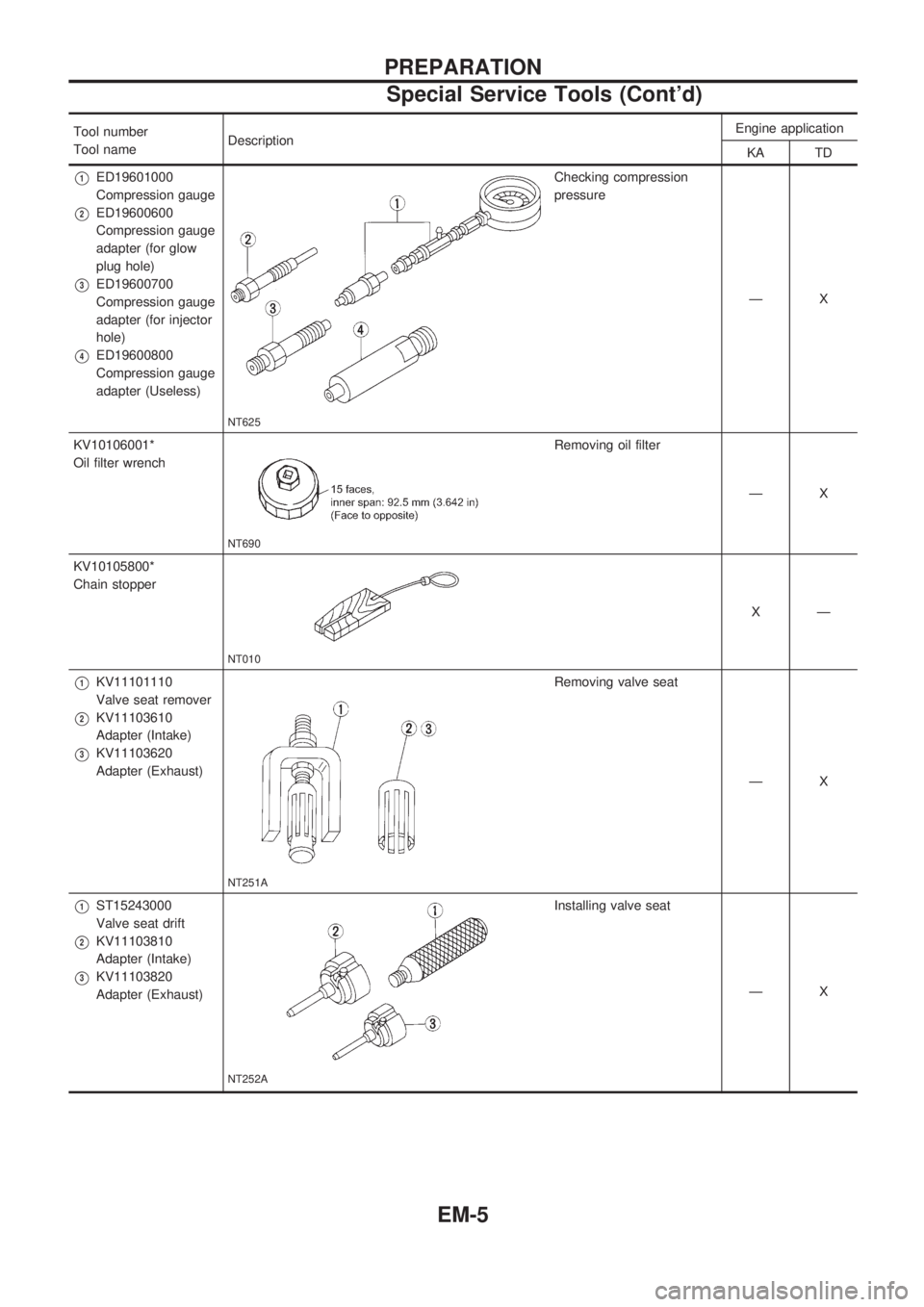
Tool number
Tool nameDescriptionEngine application
KA TD
V1ED19601000
Compression gauge
V2ED19600600
Compression gauge
adapter (for glow
plug hole)
V3ED19600700
Compression gauge
adapter (for injector
hole)
V4ED19600800
Compression gauge
adapter (Useless)
NT625
Checking compression
pressure
ÐX
KV10106001*
Oil filter wrench
NT690
Removing oil filter
ÐX
KV10105800*
Chain stopper
NT010
XÐ
V1KV11101110
Valve seat remover
V2KV11103610
Adapter (Intake)
V3KV11103620
Adapter (Exhaust)
NT251A
Removing valve seat
ÐX
V1ST15243000
Valve seat drift
V2KV11103810
Adapter (Intake)
V3KV11103820
Adapter (Exhaust)
NT252A
Installing valve seat
ÐX
PREPARATION
Special Service Tools (Cont'd)
EM-5