Page 1513 of 1659
VA
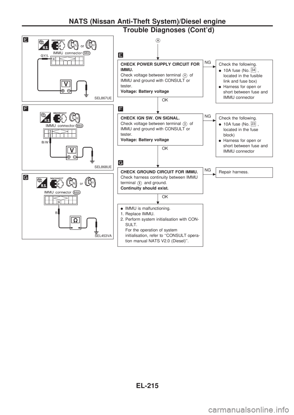
CHECK POWER SUPPLY CIRCUIT FOR
IMMU.
Check voltage between terminal
V4of
IMMU and ground with CONSULT or
tester.
Voltage: Battery voltage
OK
cNG
Check the following.
l10A fuse (No.34,
located in the fusible
link and fuse box)
lHarness for open or
short between fuse and
IMMU connector
CHECK IGN SW. ON SIGNAL.
Check voltage between terminal
V3of
IMMU and ground with CONSULT or
tester.
Voltage: Battery voltage
OK
cNG
Check the following.
l10A fuse (No.23,
located in the fuse
block)
lHarness for open or
short between fuse and
IMMU connector
CHECK GROUND CIRCUIT FOR IMMU.
Check harness continuity between IMMU
terminal
V9and ground.
Continuity should exist.
OK
cNG
Repair harness.
lIMMU is malfunctioning.
1. Replace IMMU.
2. Perform system initialisation with CON-
SULT.
For the operation of system
initialisation, refer to ``CONSULT opera-
tion manual NATS V2.0 (Diesel)''.
SEL867UE
SEL868UE
SEL453VA
.
.
.
.
NATS (Nissan Anti-Theft System)/Diesel engine
Trouble Diagnoses (Cont'd)
EL-215
Page 1514 of 1659
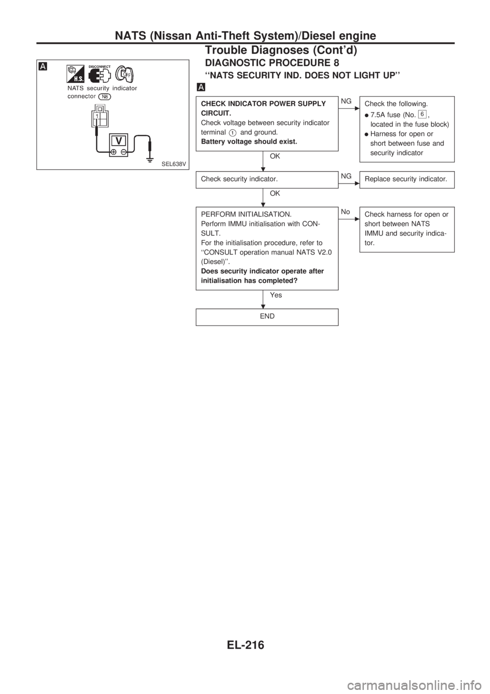
DIAGNOSTIC PROCEDURE 8
``NATS SECURITY IND. DOES NOT LIGHT UP''
CHECK INDICATOR POWER SUPPLY
CIRCUIT.
Check voltage between security indicator
terminal
V1and ground.
Battery voltage should exist.
OK
cNG
Check the following.
l7.5A fuse (No.6,
located in the fuse block)
lHarness for open or
short between fuse and
security indicator
Check security indicator.
OK
cNG
Replace security indicator.
PERFORM INITIALISATION.
Perform IMMU initialisation with CON-
SULT.
For the initialisation procedure, refer to
``CONSULT operation manual NATS V2.0
(Diesel)''.
Does security indicator operate after
initialisation has completed?
Yes
cNo
Check harness for open or
short between NATS
IMMU and security indica-
tor.
END
SEL638V.
.
.
NATS (Nissan Anti-Theft System)/Diesel engine
Trouble Diagnoses (Cont'd)
EL-216
Page 1563 of 1659
Measurement of Compression Pressure
1. Warm up engine.
2. Turn ignition switch OFF.
3. Release fuel pressure.
Refer to EC section (``Fuel Pressure Release'', ``BASIC SER-
VICE PROCEDURE'').
4. Remove all spark plugs.
5. Disconnect distributor center cable.
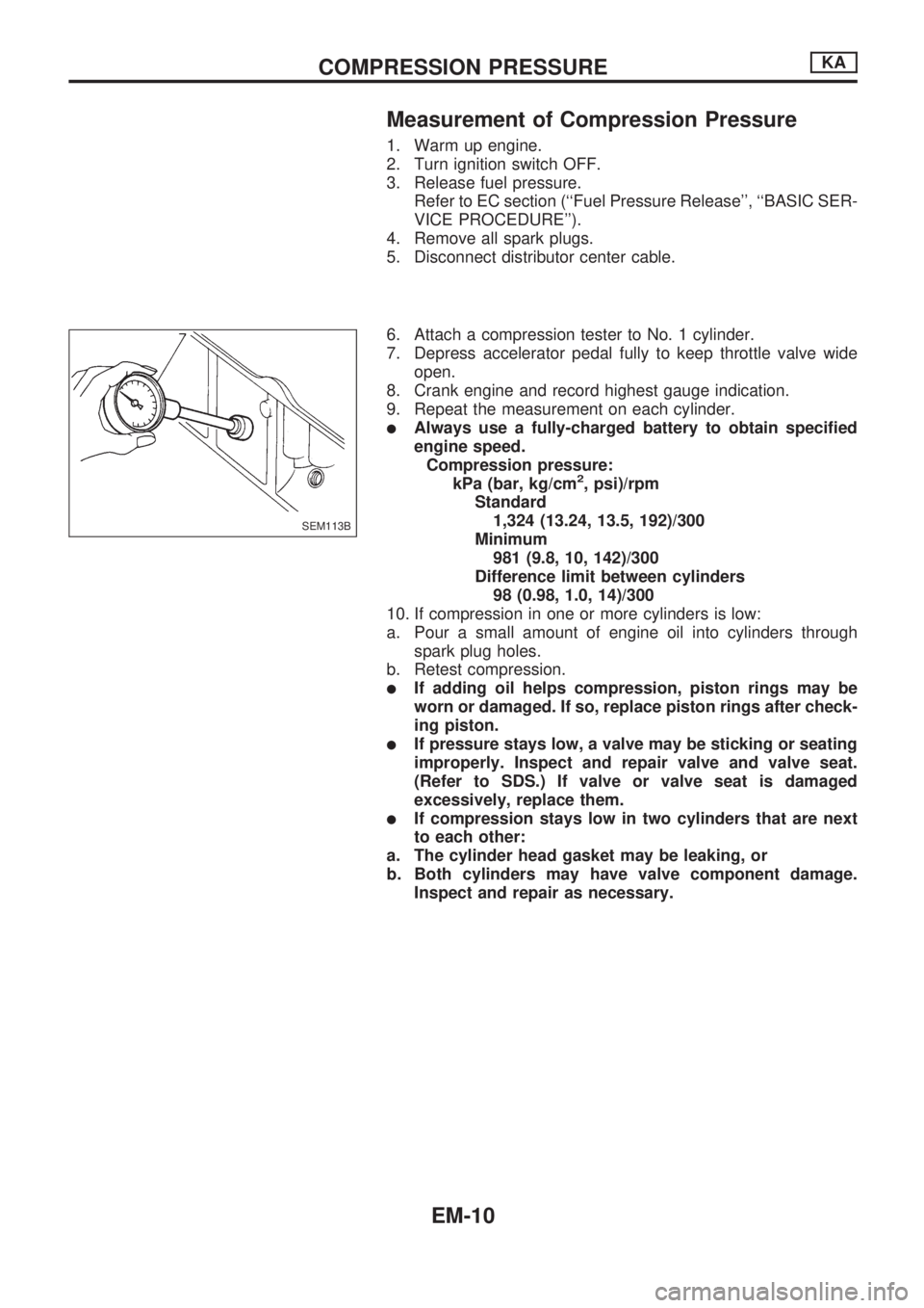
6. Attach a compression tester to No. 1 cylinder.
7. Depress accelerator pedal fully to keep throttle valve wide
open.
8. Crank engine and record highest gauge indication.
9. Repeat the measurement on each cylinder.
lAlways use a fully-charged battery to obtain specified
engine speed.
Compression pressure:
kPa (bar, kg/cm
2, psi)/rpm
Standard
1,324 (13.24, 13.5, 192)/300
Minimum
981 (9.8, 10, 142)/300
Difference limit between cylinders
98 (0.98, 1.0, 14)/300
10. If compression in one or more cylinders is low:
a. Pour a small amount of engine oil into cylinders through
spark plug holes.
b. Retest compression.
lIf adding oil helps compression, piston rings may be
worn or damaged. If so, replace piston rings after check-
ing piston.
lIf pressure stays low, a valve may be sticking or seating
improperly. Inspect and repair valve and valve seat.
(Refer to SDS.) If valve or valve seat is damaged
excessively, replace them.
lIf compression stays low in two cylinders that are next
to each other:
a. The cylinder head gasket may be leaking, or
b. Both cylinders may have valve component damage.
Inspect and repair as necessary.
SEM113B
COMPRESSION PRESSUREKA
EM-10
Page 1566 of 1659
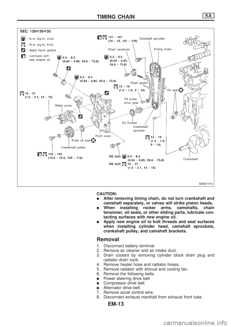
CAUTION:
lAfter removing timing chain, do not turn crankshaft and
camshaft separately, or valves will strike piston heads.
lWhen installing rocker arms, camshafts, chain
tensioner, oil seals, or other sliding parts, lubricate con-
tacting surfaces with new engine oil.
lApply new engine oil to bolt threads and seat surfaces
when installing cylinder head, camshaft sprockets,
crankshaft pulley, and camshaft brackets.
Removal
1. Disconnect battery terminal.
2. Remove air cleaner and air intake duct.
3. Drain coolant by removing cylinder block drain plug and
radiator drain cock.
4. Remove heater hose and radiator hoses.
5. Remove radiator with shroud and cooling fan.
6. Remove the following belts.
lPower steering drive belt
lCompressor drive belt
lAlternator drive belt
7. Remove accel control wire.
8. Disconnect exhaust manifold from exhaust front tube.
SEM571FA
TIMING CHAINKA
EM-13
Page 1590 of 1659
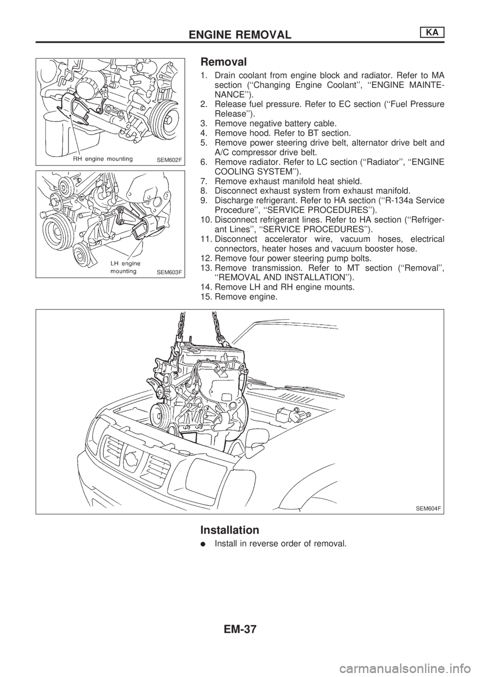
Removal
1. Drain coolant from engine block and radiator. Refer to MA
section (``Changing Engine Coolant'', ``ENGINE MAINTE-
NANCE'').
2. Release fuel pressure. Refer to EC section (``Fuel Pressure
Release'').
3. Remove negative battery cable.
4. Remove hood. Refer to BT section.
5. Remove power steering drive belt, alternator drive belt and
A/C compressor drive belt.
6. Remove radiator. Refer to LC section (``Radiator'', ``ENGINE
COOLING SYSTEM'').
7. Remove exhaust manifold heat shield.
8. Disconnect exhaust system from exhaust manifold.
9. Discharge refrigerant. Refer to HA section (``R-134a Service
Procedure'', ``SERVICE PROCEDURES'').
10. Disconnect refrigerant lines. Refer to HA section (``Refriger-
ant Lines'', ``SERVICE PROCEDURES'').
11. Disconnect accelerator wire, vacuum hoses, electrical
connectors, heater hoses and vacuum booster hose.
12. Remove four power steering pump bolts.
13. Remove transmission. Refer to MT section (``Removal'',
``REMOVAL AND INSTALLATION'').
14. Remove LH and RH engine mounts.
15. Remove engine.
Installation
lInstall in reverse order of removal.
SEM602F
SEM603F
SEM604F
ENGINE REMOVALKA
EM-37