Page 407 of 1659

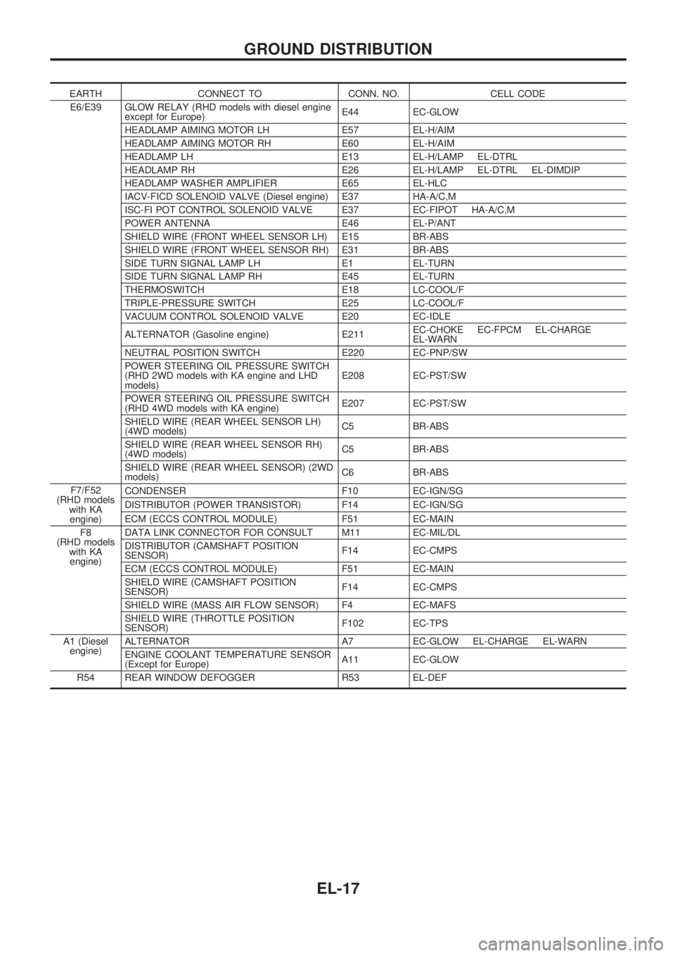
EARTH CONNECT TO CONN. NO. CELL CODE
E6/E39 GLOW RELAY (RHD models with diesel engine
except for Europe)E44 EC-GLOW
HEADLAMP AIMING MOTOR LH E57 EL-H/AIM
HEADLAMP AIMING MOTOR RH E60 EL-H/AIM
HEADLAMP LH E13 EL-H/LAMP EL-DTRL
HEADLAMP RH E26 EL-H/LAMP EL-DTRL EL-DIMDIP
HEADLAMP WASHER AMPLIFIER E65 EL-HLC
IACV-FICD SOLENOID VALVE (Diesel engine) E37 HA-A/C,M
ISC-FI POT CONTROL SOLENOID VALVE E37 EC-FIPOT HA-A/C,M
POWER ANTENNA E46 EL-P/ANT
SHIELD WIRE (FRONT WHEEL SENSOR LH) E15 BR-ABS
SHIELD WIRE (FRONT WHEEL SENSOR RH) E31 BR-ABS
SIDE TURN SIGNAL LAMP LH E1 EL-TURN
SIDE TURN SIGNAL LAMP RH E45 EL-TURN
THERMOSWITCH E18 LC-COOL/F
TRIPLE-PRESSURE SWITCH E25 LC-COOL/F
VACUUM CONTROL SOLENOID VALVE E20 EC-IDLE
ALTERNATOR (Gasoline engine) E211EC-CHOKE EC-FPCM EL-CHARGE
EL-WARN
NEUTRAL POSITION SWITCH E220 EC-PNP/SW
POWER STEERING OIL PRESSURE SWITCH
(RHD 2WD models with KA engine and LHD
models)E208 EC-PST/SW
POWER STEERING OIL PRESSURE SWITCH
(RHD 4WD models with KA engine)E207 EC-PST/SW
SHIELD WIRE (REAR WHEEL SENSOR LH)
(4WD models)C5 BR-ABS
SHIELD WIRE (REAR WHEEL SENSOR RH)
(4WD models)C5 BR-ABS
SHIELD WIRE (REAR WHEEL SENSOR) (2WD
models)C6 BR-ABS
F7/F52
(RHD models
with KA
engine)CONDENSER F10 EC-IGN/SG
DISTRIBUTOR (POWER TRANSISTOR) F14 EC-IGN/SG
ECM (ECCS CONTROL MODULE) F51 EC-MAIN
F8
(RHD models
with KA
engine)DATA LINK CONNECTOR FOR CONSULT M11 EC-MIL/DL
DISTRIBUTOR (CAMSHAFT POSITION
SENSOR)F14 EC-CMPS
ECM (ECCS CONTROL MODULE) F51 EC-MAIN
SHIELD WIRE (CAMSHAFT POSITION
SENSOR)F14 EC-CMPS
SHIELD WIRE (MASS AIR FLOW SENSOR) F4 EC-MAFS
SHIELD WIRE (THROTTLE POSITION
SENSOR)F102 EC-TPS
A1 (Diesel
engine)ALTERNATOR A7 EC-GLOW EL-CHARGE EL-WARN
ENGINE COOLANT TEMPERATURE SENSOR
(Except for Europe)A11 EC-GLOW
R54 REAR WINDOW DEFOGGER R53 EL-DEF
GROUND DISTRIBUTION
EL-17
Page 434 of 1659
Wiring Diagram Ð H/LAMP Ð/LHD Models
HEL898
HEADLAMP Ð Conventional Type Ð
EL-44
Page 435 of 1659
HEL321A
HEADLAMP Ð Conventional Type Ð
Wiring Diagram Ð H/LAMP Ð/LHD Models
(Cont'd)
EL-45
Page 436 of 1659
Wiring Diagram Ð H/LAMP Ð/RHD Models
HEL900
HEADLAMP Ð Conventional Type Ð
EL-46
Page 437 of 1659
HEL901
HEADLAMP Ð Conventional Type Ð
Wiring Diagram Ð H/LAMP Ð/RHD Models
(Cont'd)
EL-47
Page 438 of 1659

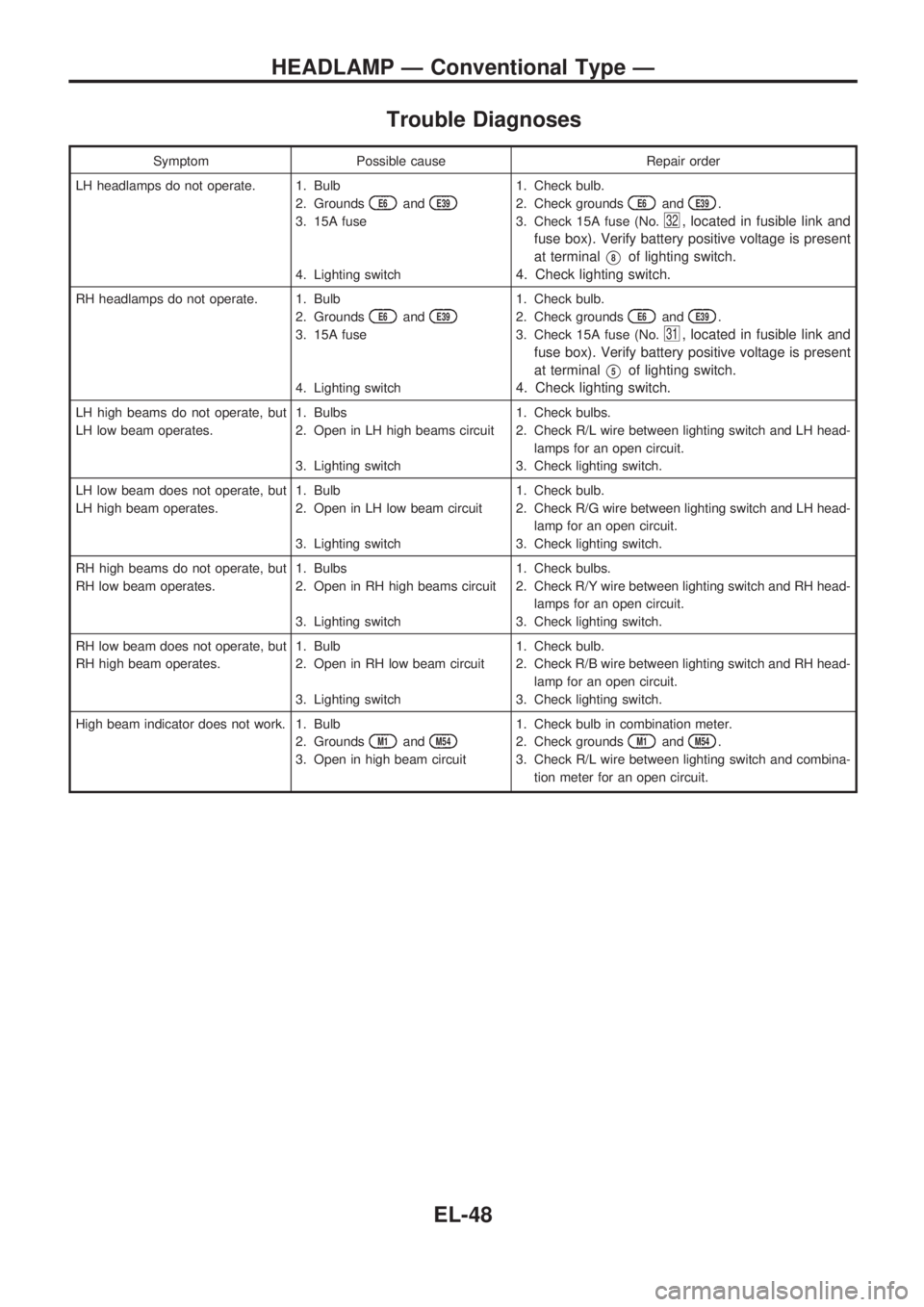
Trouble Diagnoses
Symptom Possible cause Repair order
LH headlamps do not operate. 1. Bulb
2. Grounds
E6andE39
3. 15A fuse
4. Lighting switch1. Check bulb.
2. Check grounds
E6andE39.
3. Check 15A fuse (No.
32, located in fusible link and
fuse box). Verify battery positive voltage is present
at terminal
V8of lighting switch.
4. Check lighting switch.
RH headlamps do not operate. 1. Bulb
2. Grounds
E6andE39
3. 15A fuse
4. Lighting switch1. Check bulb.
2. Check grounds
E6andE39.
3. Check 15A fuse (No.
31, located in fusible link and
fuse box). Verify battery positive voltage is present
at terminal
V5of lighting switch.
4. Check lighting switch.
LH high beams do not operate, but
LH low beam operates.1. Bulbs
2. Open in LH high beams circuit
3. Lighting switch1. Check bulbs.
2. Check R/L wire between lighting switch and LH head-
lamps for an open circuit.
3. Check lighting switch.
LH low beam does not operate, but
LH high beam operates.1. Bulb
2. Open in LH low beam circuit
3. Lighting switch1. Check bulb.
2. Check R/G wire between lighting switch and LH head-
lamp for an open circuit.
3. Check lighting switch.
RH high beams do not operate, but
RH low beam operates.1. Bulbs
2. Open in RH high beams circuit
3. Lighting switch1. Check bulbs.
2. Check R/Y wire between lighting switch and RH head-
lamps for an open circuit.
3. Check lighting switch.
RH low beam does not operate, but
RH high beam operates.1. Bulb
2. Open in RH low beam circuit
3. Lighting switch1. Check bulb.
2. Check R/B wire between lighting switch and RH head-
lamp for an open circuit.
3. Check lighting switch.
High beam indicator does not work. 1. Bulb
2. Grounds
M1andM54
3. Open in high beam circuit1. Check bulb in combination meter.
2. Check grounds
M1andM54.
3. Check R/L wire between lighting switch and combina-
tion meter for an open circuit.
HEADLAMP Ð Conventional Type Ð
EL-48
Page 439 of 1659

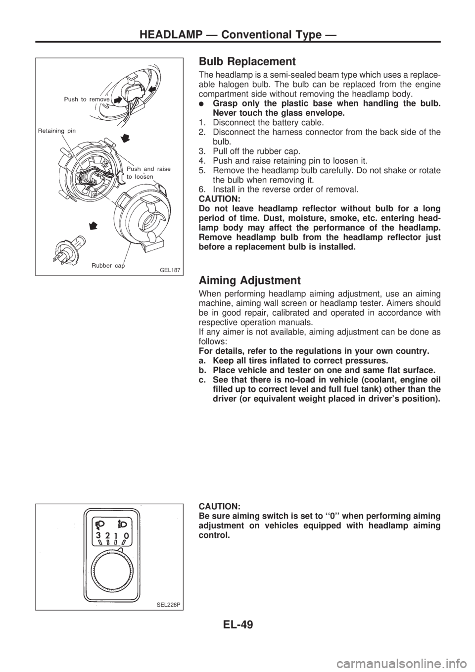
Bulb Replacement
The headlamp is a semi-sealed beam type which uses a replace-
able halogen bulb. The bulb can be replaced from the engine
compartment side without removing the headlamp body.
lGrasp only the plastic base when handling the bulb.
Never touch the glass envelope.
1. Disconnect the battery cable.
2. Disconnect the harness connector from the back side of the
bulb.
3. Pull off the rubber cap.
4. Push and raise retaining pin to loosen it.
5. Remove the headlamp bulb carefully. Do not shake or rotate
the bulb when removing it.
6. Install in the reverse order of removal.
CAUTION:
Do not leave headlamp reflector without bulb for a long
period of time. Dust, moisture, smoke, etc. entering head-
lamp body may affect the performance of the headlamp.
Remove headlamp bulb from the headlamp reflector just
before a replacement bulb is installed.
Aiming Adjustment
When performing headlamp aiming adjustment, use an aiming
machine, aiming wall screen or headlamp tester. Aimers should
be in good repair, calibrated and operated in accordance with
respective operation manuals.
If any aimer is not available, aiming adjustment can be done as
follows:
For details, refer to the regulations in your own country.
a. Keep all tires inflated to correct pressures.
b. Place vehicle and tester on one and same flat surface.
c. See that there is no-load in vehicle (coolant, engine oil
filled up to correct level and full fuel tank) other than the
driver (or equivalent weight placed in driver's position).
CAUTION:
Be sure aiming switch is set to ``0'' when performing aiming
adjustment on vehicles equipped with headlamp aiming
control.
GEL187
SEL226P
HEADLAMP Ð Conventional Type Ð
EL-49
Page 440 of 1659
Low Beam
1. Turn headlamp low beam on.
2. Use adjusting screws to perform aiming adjustment.
lFirst tighten the adjusting screw all the way and then
make adjustment by loosening the screw.
lAdjust headlamps so that main axis of light is parallel to
center line of body and is aligned with point P shown in
illustration.
lFigure to the left shows headlamp aiming pattern for
driving on right side of road; for driving on left side of
road, aiming pattern is reversed.
lDotted lines in illustration show center of headlamp.
``H'': Horizontal center line of headlamps
``W
L'': Distance between each headlamp center
``L'': 5,000 mm (196.85 in)
``C'': 65 mm (2.56 in)
GEL188
SEL254I
HEADLAMP Ð Conventional Type Ð
EL-50