1998 NISSAN PATROL checking oil
[x] Cancel search: checking oilPage 46 of 128
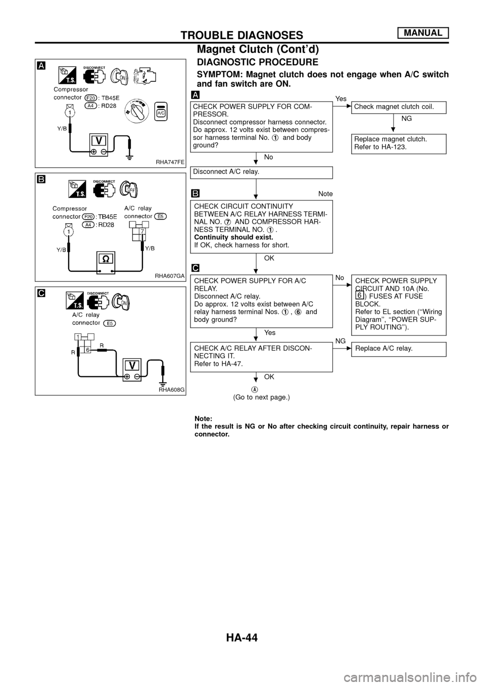
DIAGNOSTIC PROCEDURE
SYMPTOM: Magnet clutch does not engage when A/C switch
and fan switch are ON.
CHECK POWER SUPPLY FOR COM-
PRESSOR.
Disconnect compressor harness connector.
Do approx. 12 volts exist between compres-
sor harness terminal No.j
1and body
ground?
No
cYe s
Check magnet clutch coil.
NG
Replace magnet clutch.
Refer to HA-123.
Disconnect A/C relay.
Note
CHECK CIRCUIT CONTINUITY
BETWEEN A/C RELAY HARNESS TERMI-
NAL NO.j
7AND COMPRESSOR HAR-
NESS TERMINAL NO.j1.
Continuity should exist.
If OK, check harness for short.
OK
CHECK POWER SUPPLY FOR A/C
RELAY.
Disconnect A/C relay.
Do approx. 12 volts exist between A/C
relay harness terminal Nos.j
1,j6and
body ground?
Ye s
cNo
CHECK POWER SUPPLY
CIRCUIT AND 10A (No.
) FUSES AT FUSE
BLOCK.
Refer to EL section (``Wiring
Diagram'', ``POWER SUP-
PLY ROUTING'').
CHECK A/C RELAY AFTER DISCON-
NECTING IT.
Refer to HA-47.
OK
cNG
Replace A/C relay.
jA(Go to next page.)
Note:
If the result is NG or No after checking circuit continuity, repair harness or
connector.
RHA747FE
RHA607GA
RHA608G
.
.
.
.
.
.
TROUBLE DIAGNOSESMANUAL
Magnet Clutch (Cont'd)
HA-44
Page 47 of 128
jA
Reconnect A/C relay.
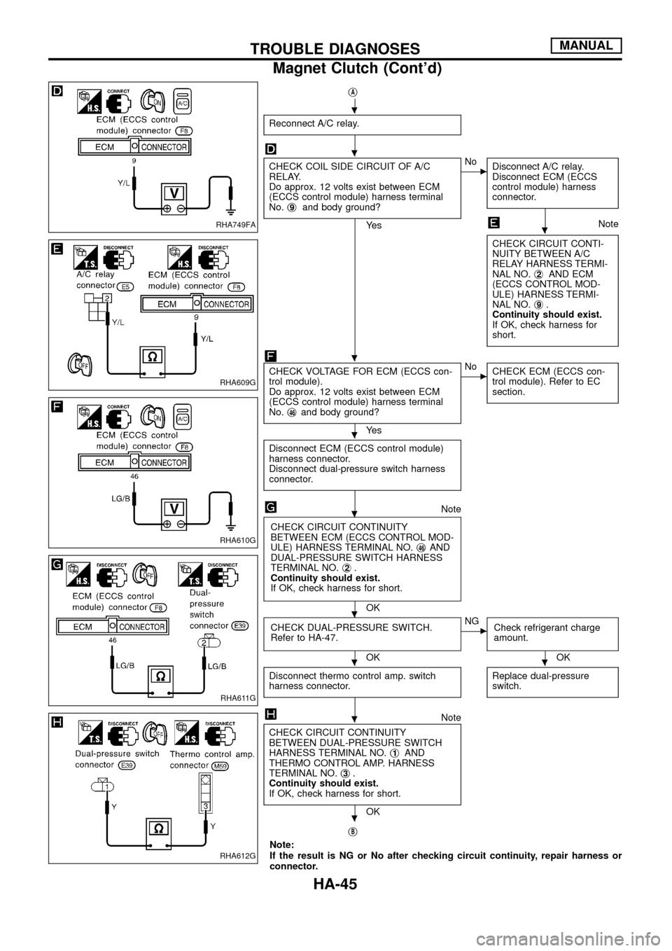
CHECK COIL SIDE CIRCUIT OF A/C
RELAY.
Do approx. 12 volts exist between ECM
(ECCS control module) harness terminal
No.j
9and body ground?
Ye s
cNo
Disconnect A/C relay.
Disconnect ECM (ECCS
control module) harness
connector.
Note
CHECK CIRCUIT CONTI-
NUITY BETWEEN A/C
RELAY HARNESS TERMI-
NAL NO.j
2AND ECM
(ECCS CONTROL MOD-
ULE) HARNESS TERMI-
NAL NO.j
9.
Continuity should exist.
If OK, check harness for
short.
CHECK VOLTAGE FOR ECM (ECCS con-
trol module).
Do approx. 12 volts exist between ECM
(ECCS control module) harness terminal
No.j
46and body ground?
Ye s
cNo
CHECK ECM (ECCS con-
trol module). Refer to EC
section.
Disconnect ECM (ECCS control module)
harness connector.
Disconnect dual-pressure switch harness
connector.
Note
CHECK CIRCUIT CONTINUITY
BETWEEN ECM (ECCS CONTROL MOD-
ULE) HARNESS TERMINAL NO.j
46AND
DUAL-PRESSURE SWITCH HARNESS
TERMINAL NO.j
2.
Continuity should exist.
If OK, check harness for short.
OK
CHECK DUAL-PRESSURE SWITCH.
Refer to HA-47.
OK
cNG
Check refrigerant charge
amount.
OK
Disconnect thermo control amp. switch
harness connector.
Replace dual-pressure
switch.
Note
CHECK CIRCUIT CONTINUITY
BETWEEN DUAL-PRESSURE SWITCH
HARNESS TERMINAL NO.j
1AND
THERMO CONTROL AMP. HARNESS
TERMINAL NO.j
3.
Continuity should exist.
If OK, check harness for short.
OK
j
B
Note:
If the result is NG or No after checking circuit continuity, repair harness or
connector.
RHA749FA
RHA609G
RHA610G
RHA611G
RHA612G
.
.
.
.
.
.
.
..
.
.
TROUBLE DIAGNOSESMANUAL
Magnet Clutch (Cont'd)
HA-45
Page 96 of 128
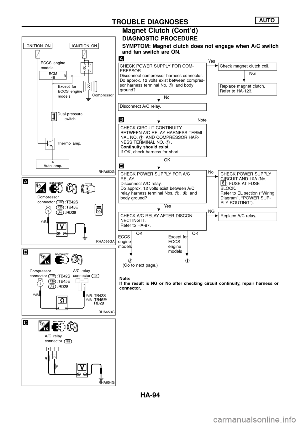
DIAGNOSTIC PROCEDURE
SYMPTOM: Magnet clutch does not engage when A/C switch
and fan switch are ON.
CHECK POWER SUPPLY FOR COM-
PRESSOR.
Disconnect compressor harness connector.
Do approx. 12 volts exist between compres-
sor harness terminal No.j
1and body
ground?
No
cYe s
Check magnet clutch coil.
NG
Replace magnet clutch.
Refer to HA-123.
Disconnect A/C relay.
Note
CHECK CIRCUIT CONTINUITY
BETWEEN A/C RELAY HARNESS TERMI-
NAL NO.j
7AND COMPRESSOR HAR-
NESS TERMINAL NO.j1.
Continuity should exist.
If OK, check harness for short.
OK
CHECK POWER SUPPLY FOR A/C
RELAY.
Disconnect A/C relay.
Do approx. 12 volts exist between A/C
relay harness terminal Nos.j
1,j6and
body ground?
Ye s
cNo
CHECK POWER SUPPLY
CIRCUIT AND 10A (No.
) FUSE AT FUSE
BLOCK.
Refer to EL section (``Wiring
Diagram'', ``POWER SUP-
PLY ROUTING'').
CHECK A/C RELAY AFTER DISCON-
NECTING IT.
Refer to HA-97.
OK OK
ECCS
engine
modelsExcept for
ECCS
engine
models
cNG
Replace A/C relay.
jA(Go to next page.)jB
Note:
If the result is NG or No after checking circuit continuity, repair harness or
connector.
RHA652G
RHA096GA
RHA653G
RHA654G
.
.
.
.
.
..
TROUBLE DIAGNOSESAUTO
Magnet Clutch (Cont'd)
HA-94
Page 97 of 128
jA
Reconnect A/C relay.
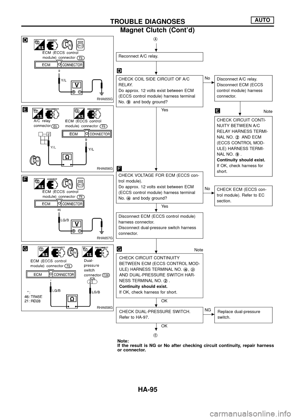
CHECK COIL SIDE CIRCUIT OF A/C
RELAY.
Do approx. 12 volts exist between ECM
(ECCS control module) harness terminal
No.j
9and body ground?
Ye s
cNo
Disconnect A/C relay.
Disconnect ECM (ECCS
control module) harness
connector.
Note
CHECK CIRCUIT CONTI-
NUITY BETWEEN A/C
RELAY HARNESS TERMI-
NAL NO.j
2AND ECM
(ECCS CONTROL MOD-
ULE) HARNESS TERMI-
NAL NO.j
9.
Continuity should exist.
If OK, check harness for
short.
CHECK VOLTAGE FOR ECM (ECCS con-
trol module).
Do approx. 12 volts exist between ECM
(ECCS control module) harness terminal
No.j
46and body ground?
Ye s
cNo
CHECK ECM (ECCS con-
trol module). Refer to EC
section.
Disconnect ECM (ECCS control module)
harness connector.
Disconnect dual-pressure switch harness
connector.
Note
CHECK CIRCUIT CONTINUITY
BETWEEN ECM (ECCS CONTROL MOD-
ULE) HARNESS TERMINAL NO.j
46,j21
AND DUAL-PRESSURE SWITCH HAR-
NESS TERMINAL NO.j
2.
Continuity should exist.
If OK, check harness for short.
OK
CHECK DUAL-PRESSURE SWITCH.
Refer to HA-97.
OK
cNG
Replace dual-pressure
switch.
jC
Note:
If the result is NG or No after checking circuit continuity, repair harness
or connector.
RHA655G
RHA656G
RHA657G
RHA658G
.
.
.
.
.
.
.
.
TROUBLE DIAGNOSESAUTO
Magnet Clutch (Cont'd)
HA-95
Page 116 of 128
Maintenance of Lubricant Quantity in
Compressor
The lubricant used to lubricate the compressor circulates through
the system with the refrigerant. Add lubricant to compressor when
replacing any component or after a large gas leakage occurred. It
is important to maintain the speci®ed amount.
If lubricant quantity is not maintained properly, the following mal-
functions may result:
+Lack of lubricant: May lead to a seized compressor
+Excessive lubricant: Inadequate cooling (thermal exchange
interference)
LUBRICANT
Name: Nissan A/C System Oil Type S
Part number: KLH00-PAGS0
CHECKING AND ADJUSTING
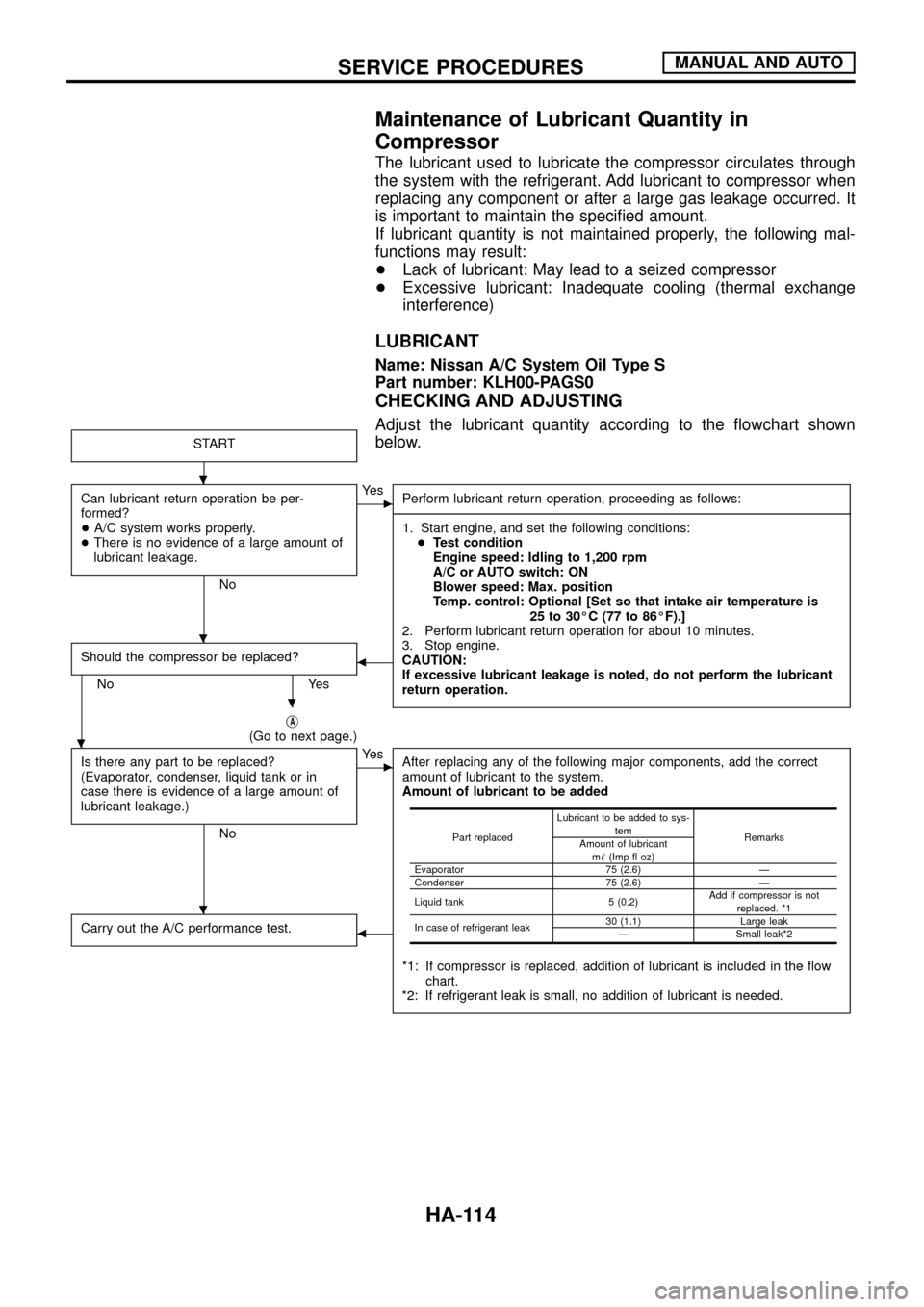
Adjust the lubricant quantity according to the ¯owchart shown
below.
START
Can lubricant return operation be per-
formed?
+A/C system works properly.
+There is no evidence of a large amount of
lubricant leakage.
No
cYe s
Perform lubricant return operation, proceeding as follows:
------------------------------------------------------------------------------------------------------------------------------------------------------------------------------------------------------------------------------------------------------------------------------------------------------------------------------------------------------------------------------------------------------------------------------------------------------------------------------------------------------------------------------------
1. Start engine, and set the following conditions:
+Test condition
Engine speed: Idling to 1,200 rpm
A/C or AUTO switch: ON
Blower speed: Max. position
Temp. control: Optional [Set so that intake air temperature is
25 to 30ÉC (77 to 86ÉF).]
2. Perform lubricant return operation for about 10 minutes.
3. Stop engine.
CAUTION:
If excessive lubricant leakage is noted, do not perform the lubricant
return operation.
Should the compressor be replaced?
No Yes
b
jA(Go to next page.)
Is there any part to be replaced?
(Evaporator, condenser, liquid tank or in
case there is evidence of a large amount of
lubricant leakage.)
No
cYe s
After replacing any of the following major components, add the correct
amount of lubricant to the system.
Amount of lubricant to be added
*1: If compressor is replaced, addition of lubricant is included in the ¯ow
chart.
*2: If refrigerant leak is small, no addition of lubricant is needed.
Carry out the A/C performance test.b
Part replacedLubricant to be added to sys-
tem
Remarks
Amount of lubricant
m!(Imp ¯ oz)
Evaporator 75 (2.6) Ð
Condenser 75 (2.6) Ð
Liquid tank 5 (0.2)Add if compressor is not
replaced. *1
In case of refrigerant leak30 (1.1) Large leak
Ð Small leak*2
.
.
.
.
.
SERVICE PROCEDURESMANUAL AND AUTO
HA-114