1998 NISSAN PATROL heater
[x] Cancel search: heaterPage 1 of 128

HEATER &
AIR CONDITIONER
SECTION
HA
CONTENTS
MANUAL AND AUTO
PRECAUTIONS AND PREPARATION............................1
Supplemental Restraint System (SRS) ``AIR
BAG'' and ``SEAT BELT PRE-TENSIONER'' ...............1
Precautions for Working with HFC-134a (R-134a) .....1
General Refrigerant Precautions .................................2
Precautions for Refrigerant Connection ......................2
Precautions for Servicing Compressor ........................6
Special Service Tools ..................................................6
HFC-134a (R-134a) Service Tools and
Equipment ....................................................................7
Precautions for Service Equipment .............................9
DESCRIPTION............................................................... 11
Refrigeration Cycle .................................................... 11
Component Layout ....................................................12
Discharge Air Flow.....................................................13
REAR HEATER
TROUBLE DIAGNOSES...............................................14
Wiring Diagram Ð R/HEAT Ð/LHD Models .............14
Wiring Diagram Ð R/HEAT Ð/RHD Models .............15
MANUAL
DESCRIPTION...............................................................16
System Description ....................................................16
Control Operation ......................................................16
TROUBLE DIAGNOSES...............................................17
Component Location..................................................17
Wiring Diagram Ð A/C, M Ð ....................................19
How to Perform Trouble Diagnoses for Quick
and Accurate Repair ..................................................21
Operational Check .....................................................22
Intake Door Motor ......................................................24
Blower Motor..............................................................28
Insufficient Cooling ....................................................32
Trouble Diagnoses for Abnormal Pressure ...............36
Insufficient Heating ....................................................39Air Outlet ....................................................................41
Magnet Clutch............................................................43
Noise ..........................................................................48
AUTO
DESCRIPTION...............................................................49
Introduction ................................................................49
Features .....................................................................49
Overview of Control System ......................................52
Control Operation ......................................................53
TROUBLE DIAGNOSES...............................................55
Component Location..................................................55
Circuit Diagram ..........................................................57
Wiring Diagram Ð A/C, A Ð .....................................58
Auto Amp. Terminals and Reference Value...............61
Self-diagnosis ............................................................63
How to Perform Trouble Diagnoses for Quick
and Accurate Repair ..................................................69
Operational Check .....................................................70
A/C System ................................................................73
Mode Door Motor.......................................................75
Air Mix Door Motor ....................................................79
Intake Door Motor ......................................................82
Blower Motor..............................................................86
Magnet Clutch............................................................92
Insufficient Cooling ....................................................98
Insufficient Heating ....................................................99
Noise ........................................................................100
Self-diagnosis ..........................................................101
Memory Function .....................................................102
Ambient Sensor .......................................................103
In-vehicle Sensor .....................................................105
Sunload Sensor .......................................................107
Intake Sensor........................................................... 110
HA
Page 16 of 128

Wiring Diagram Ð R/HEAT Ð/LHD Models
THA165
TROUBLE DIAGNOSESREAR HEATER
HA-14
Page 17 of 128

Wiring Diagram Ð R/HEAT Ð/RHD Models
THA166
TROUBLE DIAGNOSESREAR HEATER
HA-15
Page 79 of 128

Mode door control speci®cation
COMPONENT DESCRIPTION
The mode door motor is attached to the heater unit. It rotates so
that air is discharged from the outlet set by the auto ampli®er. Motor
rotation is conveyed to a link which activates the mode door.
CONTROL LINKAGE ADJUSTMENT
Mode door
1. Install mode door motor on heater unit and connect it to main
harness.
2. Set up code No.
in Self-diagnosis STEP 4. Refer to HA-67.
3. Move side link by hand and hold mode door in DEF mode.
4. Make sure mode door operates properly when changing from
code No.
toby pushing DEF switch.
VENT B/L B/L FOOT F/D DEF
RHA730G
RHA631G
TROUBLE DIAGNOSESAUTO
Mode Door Motor (Cont'd)
HA-77
Page 83 of 128

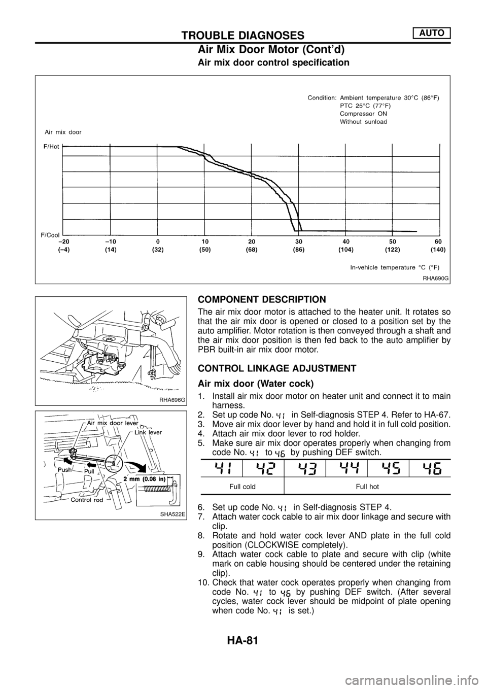
Air mix door control speci®cation
COMPONENT DESCRIPTION
The air mix door motor is attached to the heater unit. It rotates so
that the air mix door is opened or closed to a position set by the
auto ampli®er. Motor rotation is then conveyed through a shaft and
the air mix door position is then fed back to the auto ampli®er by
PBR built-in air mix door motor.
CONTROL LINKAGE ADJUSTMENT
Air mix door (Water cock)
1. Install air mix door motor on heater unit and connect it to main
harness.
2. Set up code No.
in Self-diagnosis STEP 4. Refer to HA-67.
3. Move air mix door lever by hand and hold it in full cold position.
4. Attach air mix door lever to rod holder.
5. Make sure air mix door operates properly when changing from
code No.
toby pushing DEF switch.
Full cold Full hot
6. Set up code No.in Self-diagnosis STEP 4.
7. Attach water cock cable to air mix door linkage and secure with
clip.
8. Rotate and hold water cock lever AND plate in the full cold
position (CLOCKWISE completely).
9. Attach water cock cable to plate and secure with clip (white
mark on cable housing should be centered under the retaining
clip).
10. Check that water cock operates properly when changing from
code No.
toby pushing DEF switch. (After several
cycles, water cock lever should be midpoint of plate opening
when code No.
is set.)
RHA690G
RHA696G
SHA522E
TROUBLE DIAGNOSESAUTO
Air Mix Door Motor (Cont'd)
HA-81
Page 107 of 128

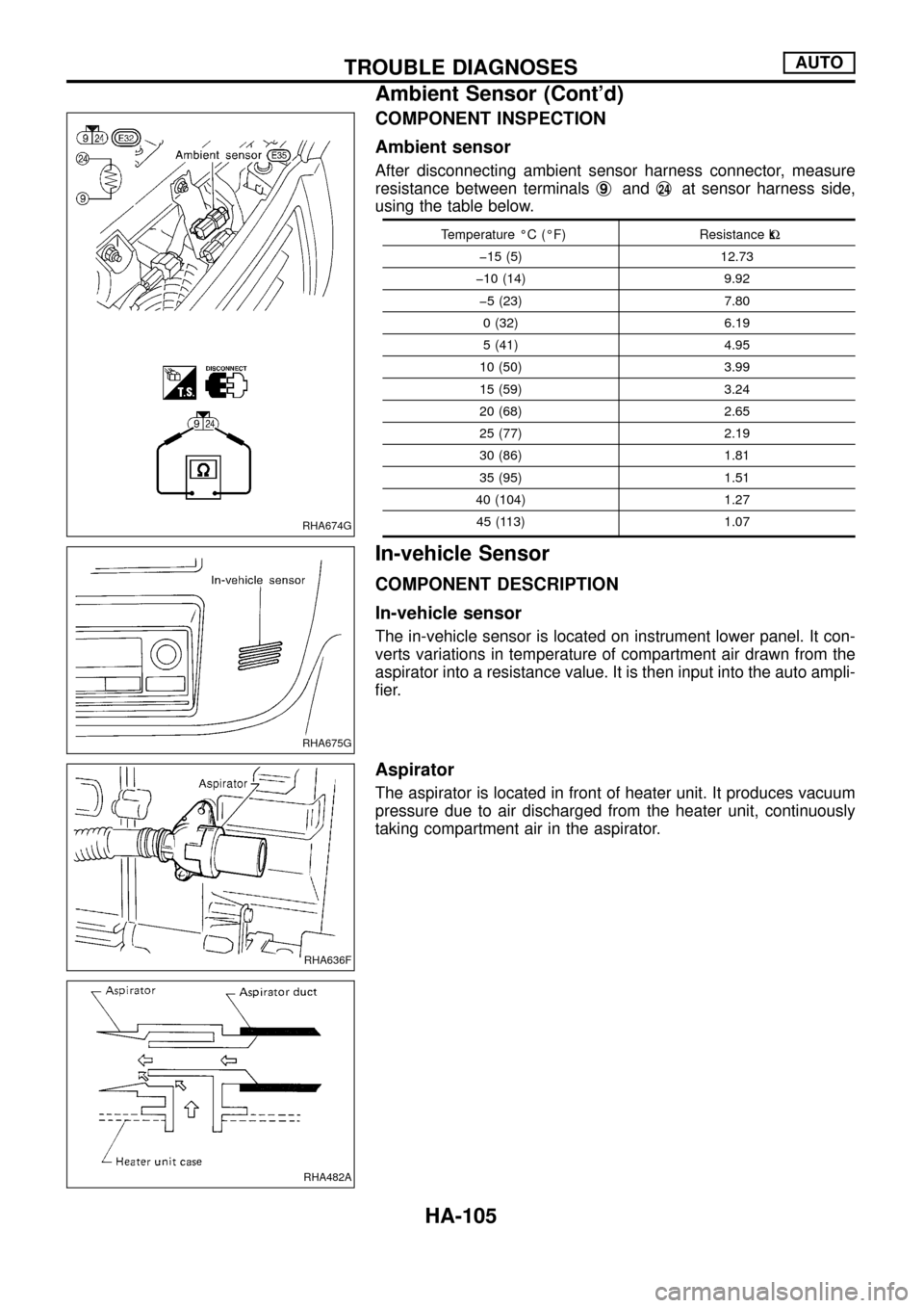
COMPONENT INSPECTION
Ambient sensor
After disconnecting ambient sensor harness connector, measure
resistance between terminalsj
9andj24at sensor harness side,
using the table below.
Temperature ÉC (ÉF) Resistance kW
þ15 (5) 12.73
þ10 (14) 9.92
þ5 (23) 7.80
0 (32) 6.19
5 (41) 4.95
10 (50) 3.99
15 (59) 3.24
20 (68) 2.65
25 (77) 2.19
30 (86) 1.81
35 (95) 1.51
40 (104) 1.27
45 (113) 1.07
In-vehicle Sensor
COMPONENT DESCRIPTION
In-vehicle sensor
The in-vehicle sensor is located on instrument lower panel. It con-
verts variations in temperature of compartment air drawn from the
aspirator into a resistance value. It is then input into the auto ampli-
®er.
Aspirator
The aspirator is located in front of heater unit. It produces vacuum
pressure due to air discharged from the heater unit, continuously
taking compartment air in the aspirator.
RHA674G
RHA675G
RHA636F
RHA482A
TROUBLE DIAGNOSESAUTO
Ambient Sensor (Cont'd)
HA-105
Page 122 of 128

3. Move probe along component approximately 25 to 50 mm (1 to
2 in)/sec.
CHECKING PROCEDURE
To prevent inaccurate or false readings, make sure there is no
refrigerant vapor or tobacco smoke in the vicinity of the
vehicle. Perform the leak test in calm area (low air/wind move-
ment) so that the leaking refrigerant is not dispersed.
1. Turn engine off.
2. Connect a suitable A/C manifold gauge set to the A/C service
ports.
3. Check if the A/C refrigerant pressure is at least 345 kPa (3.452
bar, 3.52 kg/cm
2, 50 psi) above 16ÉC (61ÉF). If less than
speci®cation, evacuate and recharge the system with the speci-
®ed amount of refrigerant.
NOTE: At temperatures below 16ÉC (61ÉF), leaks may not be
detected since the system may not reach 345 kPa
(3.452 bar, 3.52 kg/cm
2, 50 psi).
4. Conduct the leak test from the high side to the low side at points
in alphabetical order (j
a,jb......). Refer to HA-117.
Perform a leak check for the following areas carefully. Clean the
component to be checked and move the leak detector probe
completely around the connection/component.
+Compressor
Check the ®tting of high and low pressure hoses, relief valve
and shaft seal.
+Liquid tank
Check the pressure switch, tube ®tting, weld seams and the
fusible plug mounts.
+Service valves
Check all around the service valves. Ensure service valve caps
are secured on the service valves (to prevent leaks).
NOTE: After removing A/C manifold gauge set from service
valves, wipe any residue from valves to prevent any
false readings by leak detector.
+Cooling unit (Evaporator)
Turn blower fan on ``High'' for at least 15 seconds to dissipate
any refrigerant trace in the cooling unit. Insert the leak detector
probe into the drain hose immediately after stopping the
engine. (Keep the probe inserted for at least ten seconds.)
5. If a leak detector detects a leak, verify at least once by blowing
compressed air into area of suspected leak, then repeat check.
6. Do not stop when one leak is found. Continue to check for
additional leaks at all system components.
7. Start engine.
8. Set the heater A/C control as follows:
a. A/C switch ON
b. Face mode
c. Recirculation switch ON
d. Max cold temperature
e. Fan speed high
SHA708EA
SERVICE PROCEDURESMANUAL AND AUTO
Checking Refrigerant Leaks (Cont'd)
HA-120