Page 1 of 128

HEATER &
AIR CONDITIONER
SECTION
HA
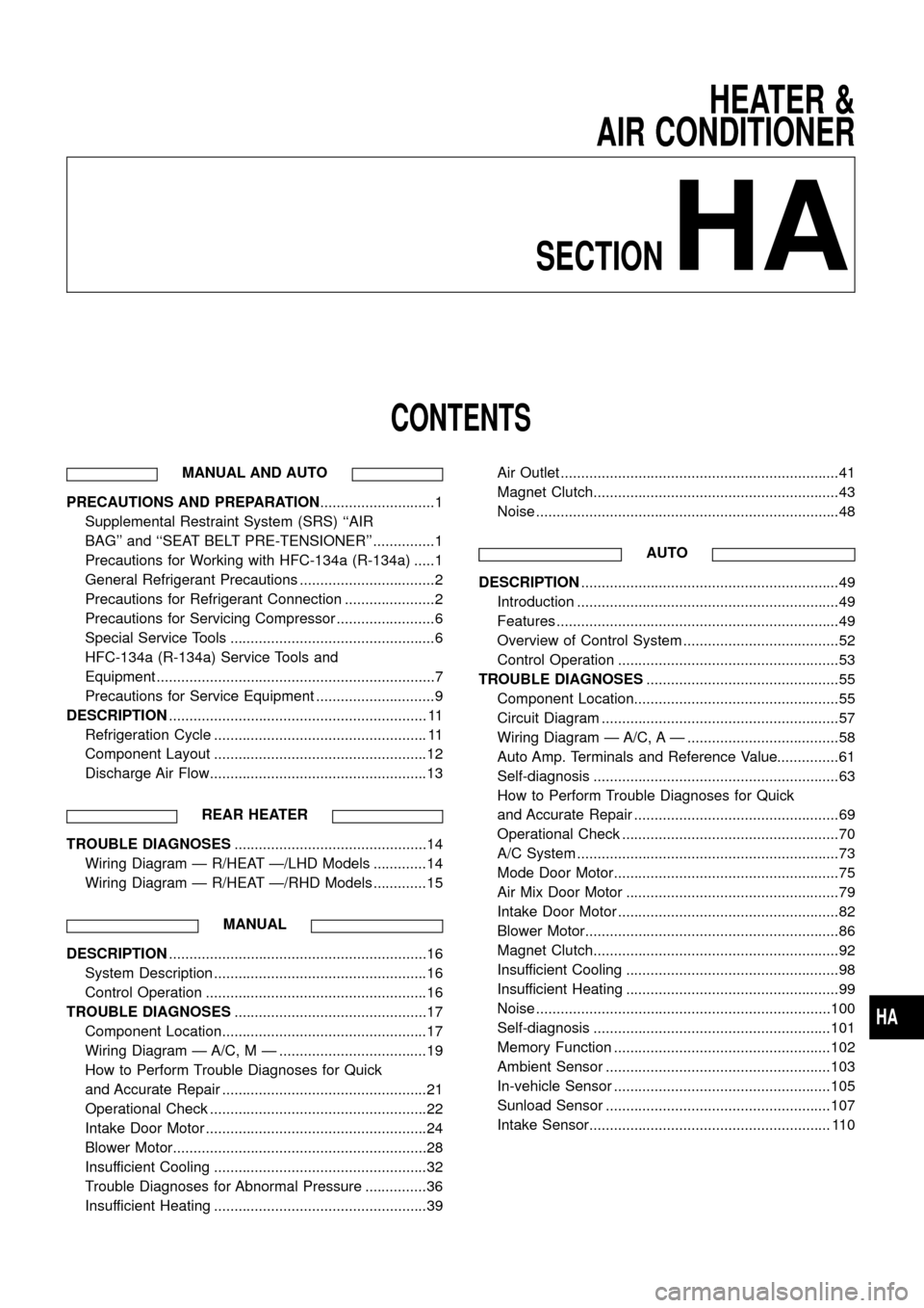
CONTENTS
MANUAL AND AUTO
PRECAUTIONS AND PREPARATION............................1
Supplemental Restraint System (SRS) ``AIR
BAG'' and ``SEAT BELT PRE-TENSIONER'' ...............1
Precautions for Working with HFC-134a (R-134a) .....1
General Refrigerant Precautions .................................2
Precautions for Refrigerant Connection ......................2
Precautions for Servicing Compressor ........................6
Special Service Tools ..................................................6
HFC-134a (R-134a) Service Tools and
Equipment ....................................................................7
Precautions for Service Equipment .............................9
DESCRIPTION............................................................... 11
Refrigeration Cycle .................................................... 11
Component Layout ....................................................12
Discharge Air Flow.....................................................13
REAR HEATER
TROUBLE DIAGNOSES...............................................14
Wiring Diagram Ð R/HEAT Ð/LHD Models .............14
Wiring Diagram Ð R/HEAT Ð/RHD Models .............15
MANUAL
DESCRIPTION...............................................................16
System Description ....................................................16
Control Operation ......................................................16
TROUBLE DIAGNOSES...............................................17
Component Location..................................................17
Wiring Diagram Ð A/C, M Ð ....................................19
How to Perform Trouble Diagnoses for Quick
and Accurate Repair ..................................................21
Operational Check .....................................................22
Intake Door Motor ......................................................24
Blower Motor..............................................................28
Insufficient Cooling ....................................................32
Trouble Diagnoses for Abnormal Pressure ...............36
Insufficient Heating ....................................................39Air Outlet ....................................................................41
Magnet Clutch............................................................43
Noise ..........................................................................48
AUTO
DESCRIPTION...............................................................49
Introduction ................................................................49
Features .....................................................................49
Overview of Control System ......................................52
Control Operation ......................................................53
TROUBLE DIAGNOSES...............................................55
Component Location..................................................55
Circuit Diagram ..........................................................57
Wiring Diagram Ð A/C, A Ð .....................................58
Auto Amp. Terminals and Reference Value...............61
Self-diagnosis ............................................................63
How to Perform Trouble Diagnoses for Quick
and Accurate Repair ..................................................69
Operational Check .....................................................70
A/C System ................................................................73
Mode Door Motor.......................................................75
Air Mix Door Motor ....................................................79
Intake Door Motor ......................................................82
Blower Motor..............................................................86
Magnet Clutch............................................................92
Insufficient Cooling ....................................................98
Insufficient Heating ....................................................99
Noise ........................................................................100
Self-diagnosis ..........................................................101
Memory Function .....................................................102
Ambient Sensor .......................................................103
In-vehicle Sensor .....................................................105
Sunload Sensor .......................................................107
Intake Sensor........................................................... 110
HA
Page 2 of 128

MANUAL AND AUTO
SERVICE PROCEDURES........................................... 112
HFC-134a (R-134a) Service Procedure .................. 112
Maintenance of Lubricant Quantity in
Compressor ............................................................. 114
Ventilation Air Filter .................................................. 116
Refrigerant Lines ..................................................... 117Checking Refrigerant Leaks .................................... 119
Compressor Mounting .............................................122
Compressor Ð DKS-17CH......................................123
Compressor Clutch ..................................................123
SERVICE DATA AND SPECIFICATIONS...................126
General Speci®cations .............................................126
Inspection and Adjustment ......................................126
When you read wiring diagrams:
+Read GI section, ``HOW TO READ WIRING DIAGRAMS''.
+See EL section, ``POWER SUPPLY ROUTING'' for power distribution circuit.
When you perform trouble diagnoses, read GI section, ``HOW TO FOLLOW FLOW
CHART IN TROUBLE DIAGNOSES'' and ``HOW TO PERFORM EFFICIENT DIAGNOSIS
FOR AN ELECTRICAL INCIDENT''.
Page 16 of 128
Wiring Diagram Ð R/HEAT Ð/LHD Models
THA165
TROUBLE DIAGNOSESREAR HEATER
HA-14
Page 17 of 128
Wiring Diagram Ð R/HEAT Ð/RHD Models
THA166
TROUBLE DIAGNOSESREAR HEATER
HA-15
Page 21 of 128
Wiring Diagram Ð A/C, M Ð
YHA157
TROUBLE DIAGNOSESMANUAL
HA-19
Page 22 of 128
YHA158
TROUBLE DIAGNOSESMANUAL
Wiring Diagram Ð A/C, M Ð (Cont'd)
HA-20
Page 28 of 128

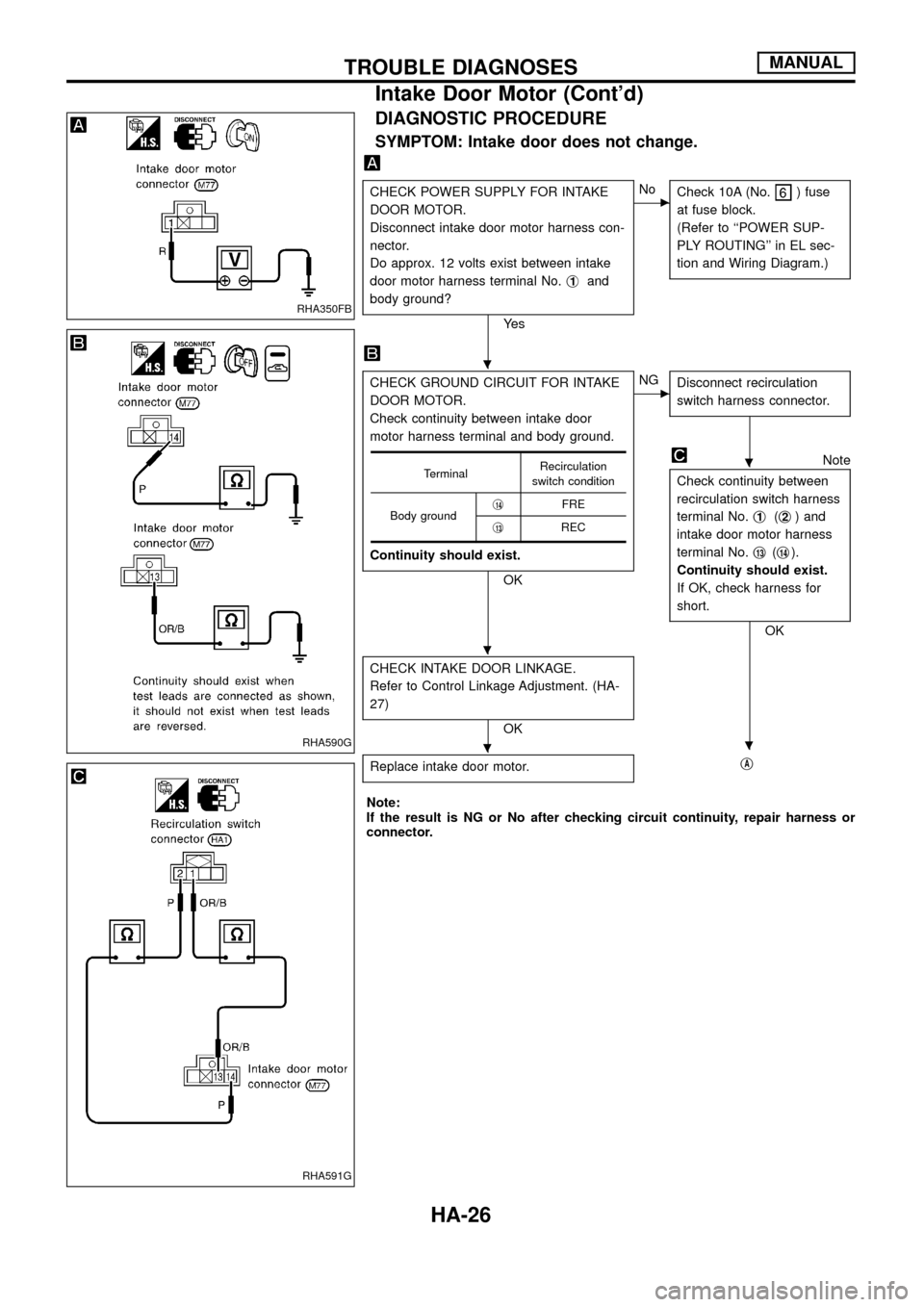
DIAGNOSTIC PROCEDURE
SYMPTOM: Intake door does not change.
CHECK POWER SUPPLY FOR INTAKE
DOOR MOTOR.
Disconnect intake door motor harness con-
nector.
Do approx. 12 volts exist between intake
door motor harness terminal No.j
1and
body ground?
Ye s
cNo
Check 10A (No.) fuse
at fuse block.
(Refer to ``POWER SUP-
PLY ROUTING'' in EL sec-
tion and Wiring Diagram.)
CHECK GROUND CIRCUIT FOR INTAKE
DOOR MOTOR.
Check continuity between intake door
motor harness terminal and body ground.
Continuity should exist.
OK
cNG
Disconnect recirculation
switch harness connector.
Note
Check continuity between
recirculation switch harness
terminal No.j
1(j2) and
intake door motor harness
terminal No.j
13(j14).
Continuity should exist.
If OK, check harness for
short.
OK
CHECK INTAKE DOOR LINKAGE.
Refer to Control Linkage Adjustment. (HA-
27)
OK
Replace intake door motor.
jA
TerminalRecirculation
switch condition
Body groundj
14FRE
j
13REC
Note:
If the result is NG or No after checking circuit continuity, repair harness or
connector.
RHA350FB
RHA590G
RHA591G
.
.
.
..
TROUBLE DIAGNOSESMANUAL
Intake Door Motor (Cont'd)
HA-26
Page 31 of 128

INCIDENTFlow chart
No.
1 Fan fails to rotate.
2 Fan does not rotate at 1-speed.
3 Fan does not rotate at 2-speed.
4 Fan does not rotate at 3-speed.
5 Fan does not rotate at 4-speed.
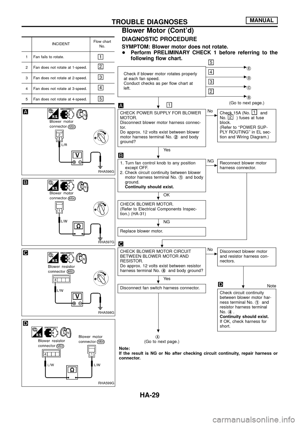
DIAGNOSTIC PROCEDURE
SYMPTOM: Blower motor does not rotate.
+Perform PRELIMINARY CHECK 1 before referring to the
following ¯ow chart.
Check if blower motor rotates properly
at each fan speed.
Conduct checks as per ¯ow chart at
left.
cjE
cjD
cjC
cjB
(Go to next page.)
CHECK POWER SUPPLY FOR BLOWER
MOTOR.
Disconnect blower motor harness connec-
tor.
Do approx. 12 volts exist between blower
motor harness terminal No.j
2and body
ground?
Ye s
cNo
Check 15A (No.and
No.) fuses at fuse
block.
(Refer to ``POWER SUP-
PLY ROUTING'' in EL sec-
tion and Wiring Diagram.)
1. Turn fan control knob to any position
except OFF.
2. Check circuit continuity between blower
motor harness terminal No.j
1and body
ground.
Continuity should exist.
OK
cNG
Reconnect blower motor
harness connector.
CHECK BLOWER MOTOR.
(Refer to Electrical Components Inspec-
tion.) (HA-31)
NG
Replace blower motor.
.
CHECK BLOWER MOTOR CIRCUIT
BETWEEN BLOWER MOTOR AND
RESISTOR.
Do approx. 12 volts exist between resistor
harness terminal No.j
4and body ground?
Ye s
cNo
Disconnect blower motor
and resistor harness con-
nectors.
Disconnect fan switch harness connector.Note
Check circuit continuity
between blower motor har-
ness terminal No.j
1and
resistor harness terminal
No.j
4.
Continuity should exist.
If OK, check harness for
short.
jA(Go to next page.)
Note:
If the result is NG or No after checking circuit continuity, repair harness or
connector.
RHA596G
RHA597G
RHA598G
RHA599G
.
.
.
.
..
.
TROUBLE DIAGNOSESMANUAL
Blower Motor (Cont'd)
HA-29