1998 NISSAN PATROL cooling
[x] Cancel search: coolingPage 1 of 128

HEATER &
AIR CONDITIONER
SECTION
HA
CONTENTS
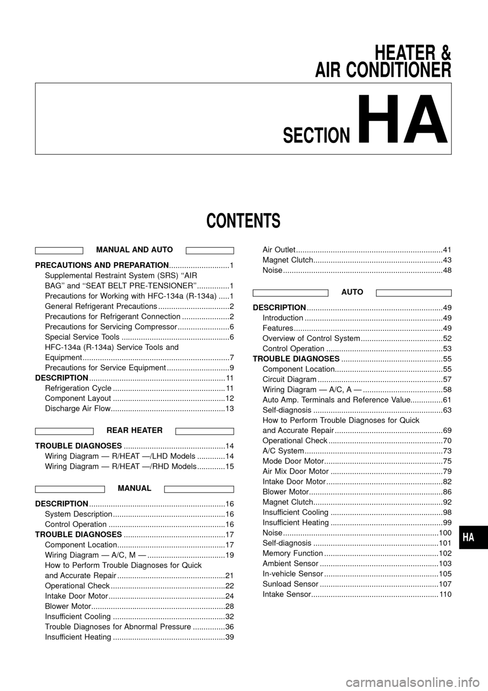
MANUAL AND AUTO
PRECAUTIONS AND PREPARATION............................1
Supplemental Restraint System (SRS) ``AIR
BAG'' and ``SEAT BELT PRE-TENSIONER'' ...............1
Precautions for Working with HFC-134a (R-134a) .....1
General Refrigerant Precautions .................................2
Precautions for Refrigerant Connection ......................2
Precautions for Servicing Compressor ........................6
Special Service Tools ..................................................6
HFC-134a (R-134a) Service Tools and
Equipment ....................................................................7
Precautions for Service Equipment .............................9
DESCRIPTION............................................................... 11
Refrigeration Cycle .................................................... 11
Component Layout ....................................................12
Discharge Air Flow.....................................................13
REAR HEATER
TROUBLE DIAGNOSES...............................................14
Wiring Diagram Ð R/HEAT Ð/LHD Models .............14
Wiring Diagram Ð R/HEAT Ð/RHD Models .............15
MANUAL
DESCRIPTION...............................................................16
System Description ....................................................16
Control Operation ......................................................16
TROUBLE DIAGNOSES...............................................17
Component Location..................................................17
Wiring Diagram Ð A/C, M Ð ....................................19
How to Perform Trouble Diagnoses for Quick
and Accurate Repair ..................................................21
Operational Check .....................................................22
Intake Door Motor ......................................................24
Blower Motor..............................................................28
Insufficient Cooling ....................................................32
Trouble Diagnoses for Abnormal Pressure ...............36
Insufficient Heating ....................................................39Air Outlet ....................................................................41
Magnet Clutch............................................................43
Noise ..........................................................................48
AUTO
DESCRIPTION...............................................................49
Introduction ................................................................49
Features .....................................................................49
Overview of Control System ......................................52
Control Operation ......................................................53
TROUBLE DIAGNOSES...............................................55
Component Location..................................................55
Circuit Diagram ..........................................................57
Wiring Diagram Ð A/C, A Ð .....................................58
Auto Amp. Terminals and Reference Value...............61
Self-diagnosis ............................................................63
How to Perform Trouble Diagnoses for Quick
and Accurate Repair ..................................................69
Operational Check .....................................................70
A/C System ................................................................73
Mode Door Motor.......................................................75
Air Mix Door Motor ....................................................79
Intake Door Motor ......................................................82
Blower Motor..............................................................86
Magnet Clutch............................................................92
Insufficient Cooling ....................................................98
Insufficient Heating ....................................................99
Noise ........................................................................100
Self-diagnosis ..........................................................101
Memory Function .....................................................102
Ambient Sensor .......................................................103
In-vehicle Sensor .....................................................105
Sunload Sensor .......................................................107
Intake Sensor........................................................... 110
HA
Page 4 of 128

General Refrigerant Precautions
WARNING:
+Do not release refrigerant into the air. Use approved recovery/recycling equipment to capture the
refrigerant every time an air conditioning system is discharged.
+Always wear eye and hand protection (goggles and gloves) when working with any refrigerant or
air conditioning system.
+Do not store or heat refrigerant containers above 52ÉC.
+Do not heat a refrigerant container with an open ¯ame; if container warming is required, place the
bottom of the container in a warm pail of water.
+Do not intentionally drop, puncture, or incinerate refrigerant containers.
+Keep refrigerant away from open ¯ames: poisonous gas will be produced if refrigerant burns.
+Refrigerant will displace oxygen, therefore be certain to work in well ventilated areas to prevent
suffocation.
+Do not introduce compressed air to any refrigerant container or refrigerant component.
Precautions for Refrigerant Connection
A new type refrigerant connection has been introduced to all refrigerant lines except the following location.
+Expansion valve to cooling unit
+A part of high-pressure line
FEATURES OF NEW TYPE REFRIGERANT CONNECTION
+The O-ring has been relocated. It has also been provided with a groove for proper installation. This elimi-
nates the chance of the O-ring being caught in, or damaged by, the mating part. The sealing direction of
the O-ring is now set vertically in relation to the contacting surface of the mating part to improve sealing
characteristics.
+The reaction force of the O-ring will not occur in the direction that causes the joint to pull out, thereby
facilitating piping connections.
CAUTION:
The new and former refrigerant connections use different O-ring con®gurations. Do not confuse
O-rings since they are not interchangeable. If a wrong O-ring is installed, refrigerant will leak at, or
around, the connection.
SHA815E
PRECAUTIONS AND PREPARATIONMANUAL AND AUTO
HA-2
Page 18 of 128

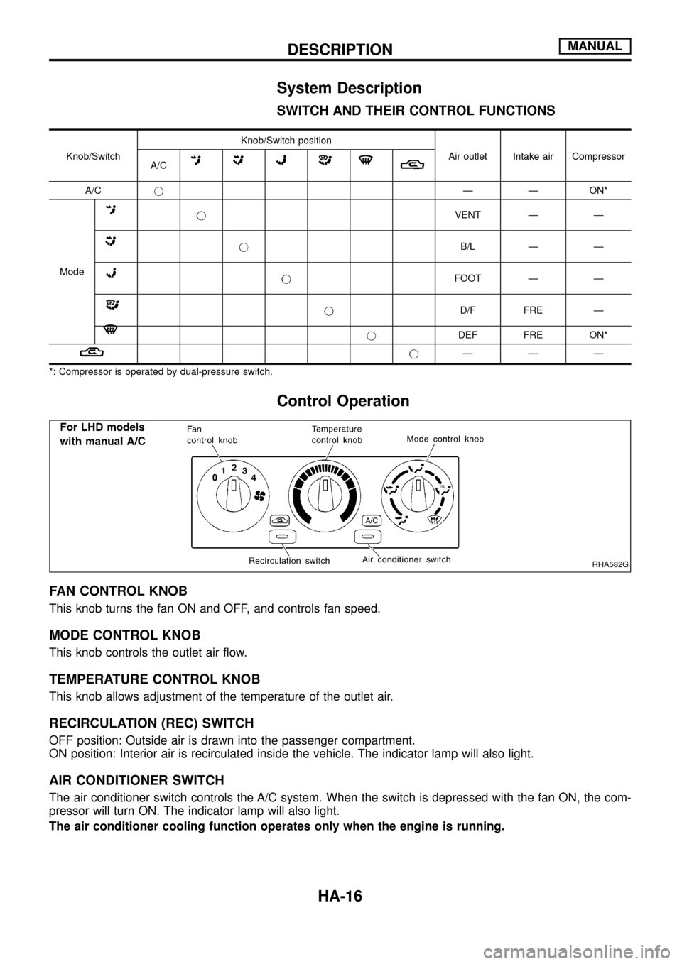
System Description
SWITCH AND THEIR CONTROL FUNCTIONS
Knob/SwitchKnob/Switch position
Air outlet Intake air Compressor
A/C
A/CjÐ Ð ON*
Mode
jVENT Ð Ð
jB/L Ð Ð
jFOOT Ð Ð
jD/F FRE Ð
jDEF FRE ON*
jÐÐÐ
*: Compressor is operated by dual-pressure switch.
Control Operation
FAN CONTROL KNOB
This knob turns the fan ON and OFF, and controls fan speed.
MODE CONTROL KNOB
This knob controls the outlet air ¯ow.
TEMPERATURE CONTROL KNOB
This knob allows adjustment of the temperature of the outlet air.
RECIRCULATION (REC) SWITCH
OFF position: Outside air is drawn into the passenger compartment.
ON position: Interior air is recirculated inside the vehicle. The indicator lamp will also light.
AIR CONDITIONER SWITCH
The air conditioner switch controls the A/C system. When the switch is depressed with the fan ON, the com-
pressor will turn ON. The indicator lamp will also light.
The air conditioner cooling function operates only when the engine is running.
RHA582G
DESCRIPTIONMANUAL
HA-16
Page 23 of 128

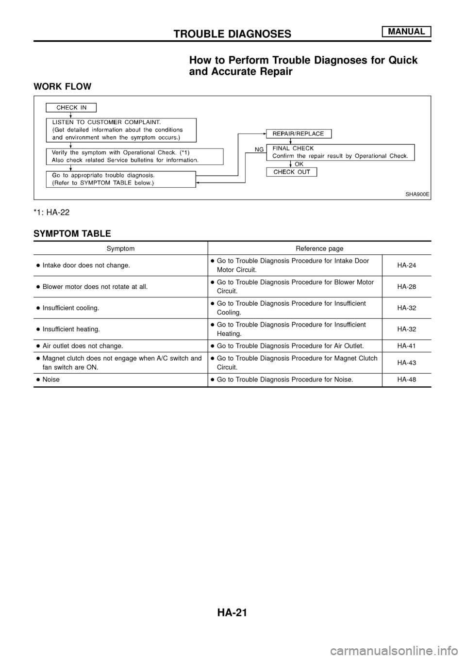
How to Perform Trouble Diagnoses for Quick
and Accurate Repair
WORK FLOW
*1: HA-22
SYMPTOM TABLE
Symptom Reference page
+Intake door does not change.+Go to Trouble Diagnosis Procedure for Intake Door
Motor Circuit.HA-24
+Blower motor does not rotate at all.+Go to Trouble Diagnosis Procedure for Blower Motor
Circuit.HA-28
+Insufficient cooling.+Go to Trouble Diagnosis Procedure for Insufficient
Cooling.HA-32
+Insufficient heating.+Go to Trouble Diagnosis Procedure for Insufficient
Heating.HA-32
+Air outlet does not change.+Go to Trouble Diagnosis Procedure for Air Outlet. HA-41
+Magnet clutch does not engage when A/C switch and
fan switch are ON.+Go to Trouble Diagnosis Procedure for Magnet Clutch
Circuit.HA-43
+Noise+Go to Trouble Diagnosis Procedure for Noise. HA-48
SHA900E
TROUBLE DIAGNOSESMANUAL
HA-21
Page 34 of 128

Insufficient Cooling
TROUBLE DIAGNOSIS PROCEDURE FOR INSUFFICIENT COOLING
SYMPTOM:
+Insufficient cooling.
Inspection ¯ow
*1: HA-40
*2: HA-35
*3: HA-33*4: HA-22
*5: HA-21*6: HA-0
*7: HA-47
RHA603G
TROUBLE DIAGNOSESMANUAL
HA-32
Page 35 of 128

PERFORMANCE TEST DIAGNOSES
*1: HA-35 *2: HA-35 *3: HA-36
MHA649A
TROUBLE DIAGNOSESMANUAL
Insufficient Cooling (Cont'd)
HA-33
Page 36 of 128

MHA650A
TROUBLE DIAGNOSESMANUAL
Insufficient Cooling (Cont'd)
HA-34
Page 37 of 128

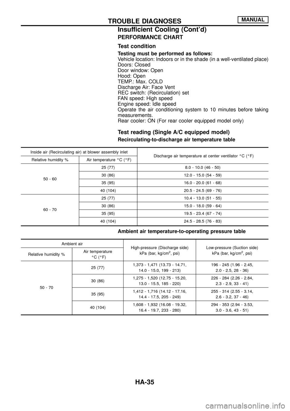
PERFORMANCE CHART
Test condition
Testing must be performed as follows:
Vehicle location: Indoors or in the shade (in a well-ventilated place)
Doors: Closed
Door window: Open
Hood: Open
TEMP.: Max. COLD
Discharge Air: Face Vent
REC switch: (Recirculation) set
FAN speed: High speed
Engine speed: Idle speed
Operate the air conditioning system to 10 minutes before taking
measurements.
Rear cooler: ON (For rear cooler equipped model only)
Test reading (Single A/C equipped model)
Recirculating-to-discharge air temperature table
Inside air (Recirculating air) at blower assembly inlet
Discharge air temperature at center ventilator ÉC (ÉF)
Relative humidity % Air temperature ÉC (ÉF)
50-6025 (77) 8.0 - 10.0 (46 - 50)
30 (86) 12.0 - 15.0 (54 - 59)
35 (95) 16.0 - 20.0 (61 - 68)
40 (104) 20.5 - 24.5 (69 - 76)
60-7025 (77) 10.4 - 13.0 (51 - 55)
30 (86) 15.0 - 18.0 (59 - 64)
35 (95) 19.5 - 23.4 (67 - 74)
40 (104) 24.5 - 28.5 (76 - 83)
Ambient air temperature-to-operating pressure table
Ambient air
High-pressure (Discharge side)
kPa (bar, kg/cm
2, psi)Low-pressure (Suction side)
kPa (bar, kg/cm2, psi)
Relative humidity %Air temperature
ÉC (ÉF)
50-7025 (77)1,373 - 1,471 (13.73 - 14.71,
14.0 - 15.0, 199 - 213)196 - 245 (1.96 - 2.45,
2.0 - 2.5, 28 - 36)
30 (86)1,275 - 1,520 (12.75 - 15.20,
13.0 - 15.5, 185 - 220)226 - 284 (2.26 - 2.84,
2.3 - 2.9, 33 - 41)
35 (95)1,412 - 1,716 (14.12 - 17.16,
14.4 - 17.5, 205 - 249)255 - 314 (2.55 - 3.14,
2.6 - 3.2, 37 - 46)
40 (104)1,608 - 1,932 (16.08 - 19.32,
16.4 - 19.7, 233 - 280)294 - 353 (2.94 - 3.53,
3.0 - 3.6, 43 - 51)
TROUBLE DIAGNOSESMANUAL
Insufficient Cooling (Cont'd)
HA-35