Page 4 of 128

General Refrigerant Precautions
WARNING:
+Do not release refrigerant into the air. Use approved recovery/recycling equipment to capture the
refrigerant every time an air conditioning system is discharged.
+Always wear eye and hand protection (goggles and gloves) when working with any refrigerant or
air conditioning system.
+Do not store or heat refrigerant containers above 52ÉC.
+Do not heat a refrigerant container with an open ¯ame; if container warming is required, place the
bottom of the container in a warm pail of water.
+Do not intentionally drop, puncture, or incinerate refrigerant containers.
+Keep refrigerant away from open ¯ames: poisonous gas will be produced if refrigerant burns.
+Refrigerant will displace oxygen, therefore be certain to work in well ventilated areas to prevent
suffocation.
+Do not introduce compressed air to any refrigerant container or refrigerant component.
Precautions for Refrigerant Connection
A new type refrigerant connection has been introduced to all refrigerant lines except the following location.
+Expansion valve to cooling unit
+A part of high-pressure line
FEATURES OF NEW TYPE REFRIGERANT CONNECTION
+The O-ring has been relocated. It has also been provided with a groove for proper installation. This elimi-
nates the chance of the O-ring being caught in, or damaged by, the mating part. The sealing direction of
the O-ring is now set vertically in relation to the contacting surface of the mating part to improve sealing
characteristics.
+The reaction force of the O-ring will not occur in the direction that causes the joint to pull out, thereby
facilitating piping connections.
CAUTION:
The new and former refrigerant connections use different O-ring con®gurations. Do not confuse
O-rings since they are not interchangeable. If a wrong O-ring is installed, refrigerant will leak at, or
around, the connection.
SHA815E
PRECAUTIONS AND PREPARATIONMANUAL AND AUTO
HA-2
Page 38 of 128

Trouble Diagnoses for Abnormal Pressure
Whenever system's high or low-pressure side is abnormal, diagnose using a manifold gauge. The marker
above the gauge scale in the following table indicates the standard (normal) pressure range. Since the stan-
dard (normal) pressure differs from vehicle to vehicle, refer to HA-35 (``Ambient air temperature-to-operating
pressure table'').
Gauge indication Refrigerant cycle Probable cause Corrective action
Both high and low-pressure
sides are too high.
AC359A
+Pressure is reduced soon
after water is splashed on
condenser.Excessive refrigerant charge in
refrigeration cycle.Reduce refrigerant until speci-
®ed pressure is obtained.
Air suction by cooling fan is
insufficient.Insufficient condenser cooling
performance.
¯
j
1Condenser ®ns are clogged.
j
2Improper fan rotation of
cooling fan.+Clean condenser.
+Check and repair cooling fan
as necessary.
+Low-pressure pipe is not
cold.
+When compressor is stopped
high-pressure value quickly
drops by approximately 196
kPa (2.0 bar, 2 kg/cm
2,28
psi). It then decreases gradu-
ally thereafter.Poor heat exchange in con-
denser.
(After compressor operation
stops, high pressure decreases
too slowly.)
¯
Air in refrigeration cycle.Evacuate repeatedly and
recharge system.
Engine tends to overheat. Engine cooling systems mal-
function.Check and repair each engine
cooling system.
+An area of the low-pressure
pipe is colder than areas
near the evaporator outlet.
+Plates are sometimes cov-
ered with frost.+Excessive liquid refrigerant
on low-pressure side.
+Excessive refrigerant dis-
charge ¯ow.
+Expansion valve is open a
little compared with the
speci®cation.
¯
j
1Improper thermal valve
installation.
j
2Improper expansion valve
adjustment.Replace expansion valve.
High-pressure side is too high
and low-pressure side is too
low.
AC360A
Upper side of condenser and
high-pressure side are hot,
however, liquid tank is not so
hot.High-pressure tube or parts
located between compressor
and condenser are clogged or
crushed.+Check and repair or replace
malfunctioning parts.
+Check lubricant for contami-
nation.
TROUBLE DIAGNOSESMANUAL
HA-36
Page 70 of 128
AUXILIARY MECHANISM: Temperature setting trimmer
The trimmer compensates for differences in range of 3ÉC between
temperature setting (displayed digitally) and temperature felt by
driver.
Operating procedures for this trimmer are as follows:
+Begin Self-diagnosis STEP 4 mode.
+Press
(fan) switch to set system in auxiliary mode.
+Turn temperature dial clockwise or counterclockwise as
desired. Temperature will change at a rate of 1ÉC each time a
switch is pressed.
When battery cable is disconnected, trimmer operation is can-
celed. Temperature set becomes that of initial condition, i.e.
0ÉC.
RHA581G
TROUBLE DIAGNOSESAUTO
Self-diagnosis (Cont'd)
HA-68
Page 109 of 128

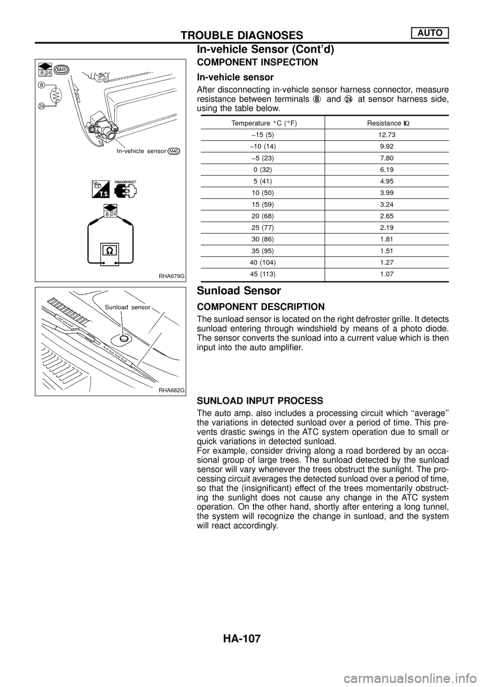
COMPONENT INSPECTION
In-vehicle sensor
After disconnecting in-vehicle sensor harness connector, measure
resistance between terminalsj
8andj24at sensor harness side,
using the table below.
Temperature ÉC (ÉF) Resistance kW
þ15 (5) 12.73
þ10 (14) 9.92
þ5 (23) 7.80
0 (32) 6.19
5 (41) 4.95
10 (50) 3.99
15 (59) 3.24
20 (68) 2.65
25 (77) 2.19
30 (86) 1.81
35 (95) 1.51
40 (104) 1.27
45 (113) 1.07
Sunload Sensor
COMPONENT DESCRIPTION
The sunload sensor is located on the right defroster grille. It detects
sunload entering through windshield by means of a photo diode.
The sensor converts the sunload into a current value which is then
input into the auto ampli®er.
SUNLOAD INPUT PROCESS
The auto amp. also includes a processing circuit which ``average''
the variations in detected sunload over a period of time. This pre-
vents drastic swings in the ATC system operation due to small or
quick variations in detected sunload.
For example, consider driving along a road bordered by an occa-
sional group of large trees. The sunload detected by the sunload
sensor will vary whenever the trees obstruct the sunlight. The pro-
cessing circuit averages the detected sunload over a period of time,
so that the (insigni®cant) effect of the trees momentarily obstruct-
ing the sunlight does not cause any change in the ATC system
operation. On the other hand, shortly after entering a long tunnel,
the system will recognize the change in sunload, and the system
will react accordingly.
RHA679G
RHA682G
TROUBLE DIAGNOSESAUTO
In-vehicle Sensor (Cont'd)
HA-107