1998 NISSAN PATROL oil pressure
[x] Cancel search: oil pressurePage 7 of 128

WARNING:
Make sure all refrigerant is discharged into the recycling equipment and the pressure in the system
is less than atmospheric pressure. Then gradually loosen the discharge side hose ®tting and remove
it.
CAUTION:
When replacing or cleaning refrigerant cycle components, observe the following.
+When the compressor is removed, store it in the same position as it is when mounted on the car.
Failure to do so will cause lubricant to enter the low pressure chamber.
+When connecting tubes, always use a torque wrench and a back-up wrench.
+After disconnecting tubes, immediately plug all openings to prevent entry of dirt and moisture.
+When installing an air conditioner in the vehicle, connect the pipes as the ®nal stage of the opera-
tion. Do not remove the seal caps of pipes and other components until just before required for
connection.
+Allow components stored in cool areas to warm to working area temperature before removing seal
caps. This prevents condensation from forming inside A/C components.
+Thoroughly remove moisture from the refrigeration system before charging the refrigerant.
+Always replace used O-rings.
+When connecting tube, apply lubricant to portions shown in illustration. Be careful not to apply
lubricant to threaded portion.
Lubricant name: Nissan A/C System Oil Type S
Part number: KLH00-PAGS0
+O-ring must be closely attached to in¯ated portion of tube.
+After inserting tube into union until O-ring is no longer visible, tighten nut to speci®ed torque.
+After connecting line, conduct leak test and make sure that there is no leakage from connections.
When the gas leaking point is found, disconnect that line and replace the O-ring. Then tighten
connections of seal seat to the speci®ed torque.
RHA861F
PRECAUTIONS AND PREPARATIONMANUAL AND AUTO
Precautions for Refrigerant Connection
(Cont'd)
HA-5
Page 11 of 128

Precautions for Service Equipment
RECOVERY/RECYCLING EQUIPMENT
Follow the manufacturer's instructions for machine operation and
machine maintenance. Never introduce any refrigerant other than
that speci®ed into the machine.
ELECTRONIC LEAK DETECTOR
Follow the manufacture's instructions for tester operation and tester
maintenance.
VACUUM PUMP
The lubricant contained inside the vacuum pump is not compatible
with the speci®ed lubricant for HFC-134a (R-134a) A/C systems.
The vent side of the vacuum pump is exposed to atmospheric
pressure. So the vacuum pump lubricant may migrate out of the
pump into the service hose. This is possible when the pump is
switched off after evacuation (vacuuming) and hose is connected
to it.
To prevent this migration, use a manual valve situated near the
hose-to-pump connection, as follows.
+Usually vacuum pumps have a manual isolator valve as part of
the pump. Close this valve to isolate the service hose from the
pump.
+For pumps without an isolator, use a hose equipped with a
manual shut-off valve near the pump end. Close the valve to
isolate the hose from the pump.
+If the hose has an automatic shut off valve, disconnect the hose
from the pump: as long as the hose is connected, the valve is
open and lubricating oil may migrate.
Some one-way valves open when vacuum is applied and close
under a no vacuum condition. Such valves may restrict the pump's
ability to pull a deep vacuum and are not recommended.
MANIFOLD GAUGE SET
Be certain that the gauge face indicates R-134a or 134a. Make
sure the gauge set has 1/2²-16 ACME threaded connections for
service hoses. Con®rm the set has been used only with refrigerant
HFC-134a (R-134a) along with speci®ed lubricant.
SERVICE HOSES
Be certain that the service hoses display the markings described
(colored hose with black stripe). All hoses must include positive
shut off devices (either manual or automatic) near the end of the
hoses opposite the manifold gauge.
RHA270D
SHA533D
RHA272D
PRECAUTIONS AND PREPARATIONMANUAL AND AUTO
HA-9
Page 13 of 128

Refrigeration Cycle
REFRIGERANT FLOW
The refrigerant ¯ow is in the standard pattern. Refrigerant ¯ows through the compressor, condenser, liquid
tank, evaporator and back to the compressor.
The refrigerant evaporation through the evaporator coil is controlled by an externally equalized expansion
valve, located inside the evaporator case.
FREEZE PROTECTION
The compressor cycles on and off to maintain the evaporator temperature within a speci®ed range. When the
evaporator coil temperature falls below a speci®ed point, the thermo control ampli®er interrupts the compres-
sor operation. When the evaporator coil temperature rises above the speci®cation, the thermo control ampli-
®er allows compressor operation.
REFRIGERANT SYSTEM PROTECTION
Dual-pressure switch
The dual-pressure switch is located on the liquid tank. If the system pressure rises or falls out of specifications,
the switch opens to interrupt compressor clutch operation.
RHA735G
DESCRIPTIONMANUAL AND AUTO
HA-11
Page 47 of 128

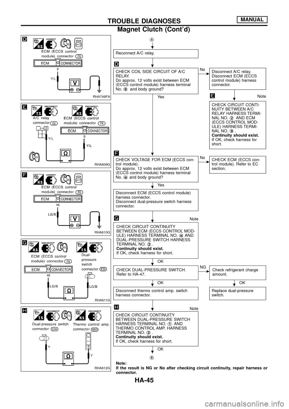
jA
Reconnect A/C relay.
CHECK COIL SIDE CIRCUIT OF A/C
RELAY.
Do approx. 12 volts exist between ECM
(ECCS control module) harness terminal
No.j
9and body ground?
Ye s
cNo
Disconnect A/C relay.
Disconnect ECM (ECCS
control module) harness
connector.
Note
CHECK CIRCUIT CONTI-
NUITY BETWEEN A/C
RELAY HARNESS TERMI-
NAL NO.j
2AND ECM
(ECCS CONTROL MOD-
ULE) HARNESS TERMI-
NAL NO.j
9.
Continuity should exist.
If OK, check harness for
short.
CHECK VOLTAGE FOR ECM (ECCS con-
trol module).
Do approx. 12 volts exist between ECM
(ECCS control module) harness terminal
No.j
46and body ground?
Ye s
cNo
CHECK ECM (ECCS con-
trol module). Refer to EC
section.
Disconnect ECM (ECCS control module)
harness connector.
Disconnect dual-pressure switch harness
connector.
Note
CHECK CIRCUIT CONTINUITY
BETWEEN ECM (ECCS CONTROL MOD-
ULE) HARNESS TERMINAL NO.j
46AND
DUAL-PRESSURE SWITCH HARNESS
TERMINAL NO.j
2.
Continuity should exist.
If OK, check harness for short.
OK
CHECK DUAL-PRESSURE SWITCH.
Refer to HA-47.
OK
cNG
Check refrigerant charge
amount.
OK
Disconnect thermo control amp. switch
harness connector.
Replace dual-pressure
switch.
Note
CHECK CIRCUIT CONTINUITY
BETWEEN DUAL-PRESSURE SWITCH
HARNESS TERMINAL NO.j
1AND
THERMO CONTROL AMP. HARNESS
TERMINAL NO.j
3.
Continuity should exist.
If OK, check harness for short.
OK
j
B
Note:
If the result is NG or No after checking circuit continuity, repair harness or
connector.
RHA749FA
RHA609G
RHA610G
RHA611G
RHA612G
.
.
.
.
.
.
.
..
.
.
TROUBLE DIAGNOSESMANUAL
Magnet Clutch (Cont'd)
HA-45
Page 97 of 128

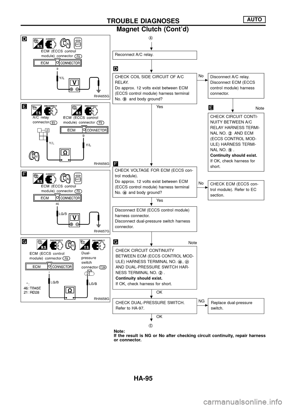
jA
Reconnect A/C relay.
CHECK COIL SIDE CIRCUIT OF A/C
RELAY.
Do approx. 12 volts exist between ECM
(ECCS control module) harness terminal
No.j
9and body ground?
Ye s
cNo
Disconnect A/C relay.
Disconnect ECM (ECCS
control module) harness
connector.
Note
CHECK CIRCUIT CONTI-
NUITY BETWEEN A/C
RELAY HARNESS TERMI-
NAL NO.j
2AND ECM
(ECCS CONTROL MOD-
ULE) HARNESS TERMI-
NAL NO.j
9.
Continuity should exist.
If OK, check harness for
short.
CHECK VOLTAGE FOR ECM (ECCS con-
trol module).
Do approx. 12 volts exist between ECM
(ECCS control module) harness terminal
No.j
46and body ground?
Ye s
cNo
CHECK ECM (ECCS con-
trol module). Refer to EC
section.
Disconnect ECM (ECCS control module)
harness connector.
Disconnect dual-pressure switch harness
connector.
Note
CHECK CIRCUIT CONTINUITY
BETWEEN ECM (ECCS CONTROL MOD-
ULE) HARNESS TERMINAL NO.j
46,j21
AND DUAL-PRESSURE SWITCH HAR-
NESS TERMINAL NO.j
2.
Continuity should exist.
If OK, check harness for short.
OK
CHECK DUAL-PRESSURE SWITCH.
Refer to HA-97.
OK
cNG
Replace dual-pressure
switch.
jC
Note:
If the result is NG or No after checking circuit continuity, repair harness
or connector.
RHA655G
RHA656G
RHA657G
RHA658G
.
.
.
.
.
.
.
.
TROUBLE DIAGNOSESAUTO
Magnet Clutch (Cont'd)
HA-95