Page 7 of 128
WARNING:
Make sure all refrigerant is discharged into the recycling equipment and the pressure in the system
is less than atmospheric pressure. Then gradually loosen the discharge side hose ®tting and remove
it.
CAUTION:
When replacing or cleaning refrigerant cycle components, observe the following.
+When the compressor is removed, store it in the same position as it is when mounted on the car.
Failure to do so will cause lubricant to enter the low pressure chamber.
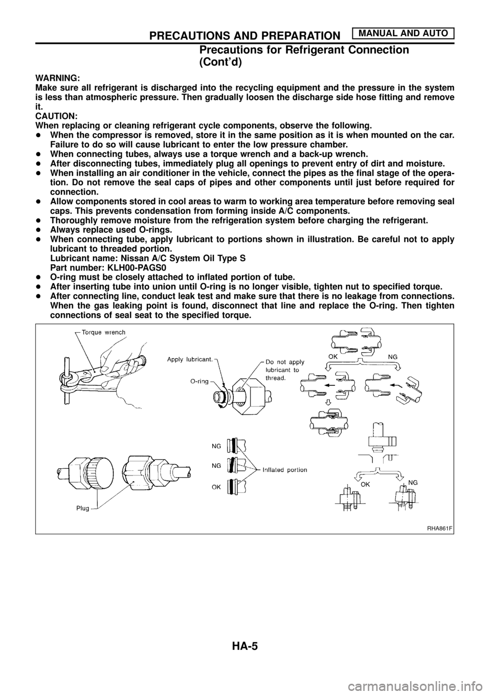
+When connecting tubes, always use a torque wrench and a back-up wrench.
+After disconnecting tubes, immediately plug all openings to prevent entry of dirt and moisture.
+When installing an air conditioner in the vehicle, connect the pipes as the ®nal stage of the opera-
tion. Do not remove the seal caps of pipes and other components until just before required for
connection.
+Allow components stored in cool areas to warm to working area temperature before removing seal
caps. This prevents condensation from forming inside A/C components.
+Thoroughly remove moisture from the refrigeration system before charging the refrigerant.
+Always replace used O-rings.
+When connecting tube, apply lubricant to portions shown in illustration. Be careful not to apply
lubricant to threaded portion.
Lubricant name: Nissan A/C System Oil Type S
Part number: KLH00-PAGS0
+O-ring must be closely attached to in¯ated portion of tube.
+After inserting tube into union until O-ring is no longer visible, tighten nut to speci®ed torque.
+After connecting line, conduct leak test and make sure that there is no leakage from connections.
When the gas leaking point is found, disconnect that line and replace the O-ring. Then tighten
connections of seal seat to the speci®ed torque.
RHA861F
PRECAUTIONS AND PREPARATIONMANUAL AND AUTO
Precautions for Refrigerant Connection
(Cont'd)
HA-5
Page 9 of 128
HFC-134a (R-134a) Service Tools and
Equipment
Never mix HFC-134a refrigerant and/or its speci®ed lubricant with CFC-12 (R-12) refrigerant and/or its lubri-
cant.
Separate and non-interchangeable service equipment must be used for each type of refrigerant/lubricant.
Refrigerant container ®ttings, service hose ®ttings and service equipment ®ttings (equipment which handles
refrigerant and/or lubricant) are different between CFC-12 (R-12) and HFC-134a (R-134a). This is to avoid
mixed use of the refrigerants/lubricant.
Adapters that convert one size ®tting to another must never be used: refrigerant/lubricant contamination will
occur and compressor failure will result.
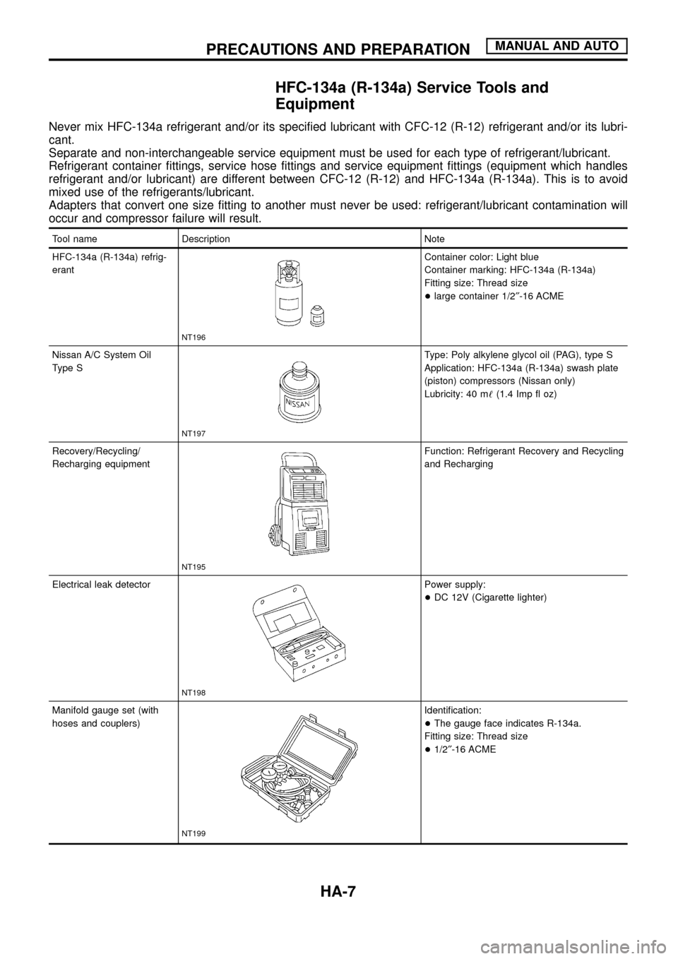
Tool name Description Note
HFC-134a (R-134a) refrig-
erant
NT196
Container color: Light blue
Container marking: HFC-134a (R-134a)
Fitting size: Thread size
+large container 1/2²-16 ACME
Nissan A/C System Oil
Type S
NT197
Type: Poly alkylene glycol oil (PAG), type S
Application: HFC-134a (R-134a) swash plate
(piston) compressors (Nissan only)
Lubricity: 40 m!(1.4 Imp ¯ oz)
Recovery/Recycling/
Recharging equipment
NT195
Function: Refrigerant Recovery and Recycling
and Recharging
Electrical leak detector
NT198
Power supply:
+DC 12V (Cigarette lighter)
Manifold gauge set (with
hoses and couplers)
NT199
Identi®cation:
+The gauge face indicates R-134a.
Fitting size: Thread size
+1/2²-16 ACME
PRECAUTIONS AND PREPARATIONMANUAL AND AUTO
HA-7
Page 12 of 128
SERVICE COUPLERS
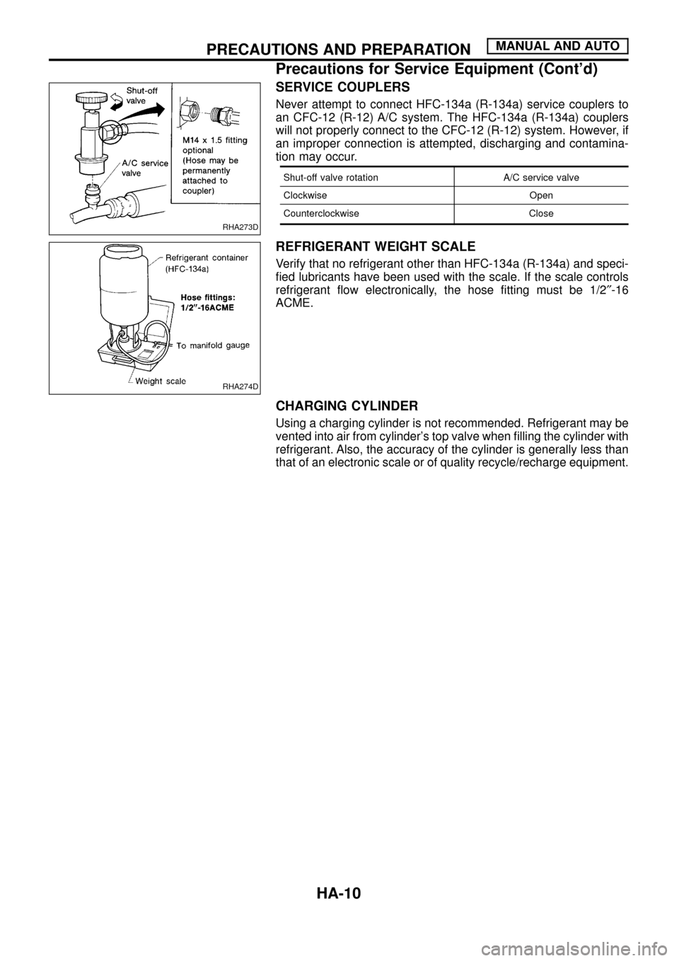
Never attempt to connect HFC-134a (R-134a) service couplers to
an CFC-12 (R-12) A/C system. The HFC-134a (R-134a) couplers
will not properly connect to the CFC-12 (R-12) system. However, if
an improper connection is attempted, discharging and contamina-
tion may occur.
Shut-off valve rotation A/C service valve
Clockwise Open
Counterclockwise Close
REFRIGERANT WEIGHT SCALE
Verify that no refrigerant other than HFC-134a (R-134a) and speci-
®ed lubricants have been used with the scale. If the scale controls
refrigerant ¯ow electronically, the hose ®tting must be 1/2²-16
ACME.
CHARGING CYLINDER
Using a charging cylinder is not recommended. Refrigerant may be
vented into air from cylinder's top valve when ®lling the cylinder with
refrigerant. Also, the accuracy of the cylinder is generally less than
that of an electronic scale or of quality recycle/recharge equipment.
RHA273D
RHA274D
PRECAUTIONS AND PREPARATIONMANUAL AND AUTO
Precautions for Service Equipment (Cont'd)
HA-10
Page 114 of 128
HFC-134a (R-134a) Service Procedure
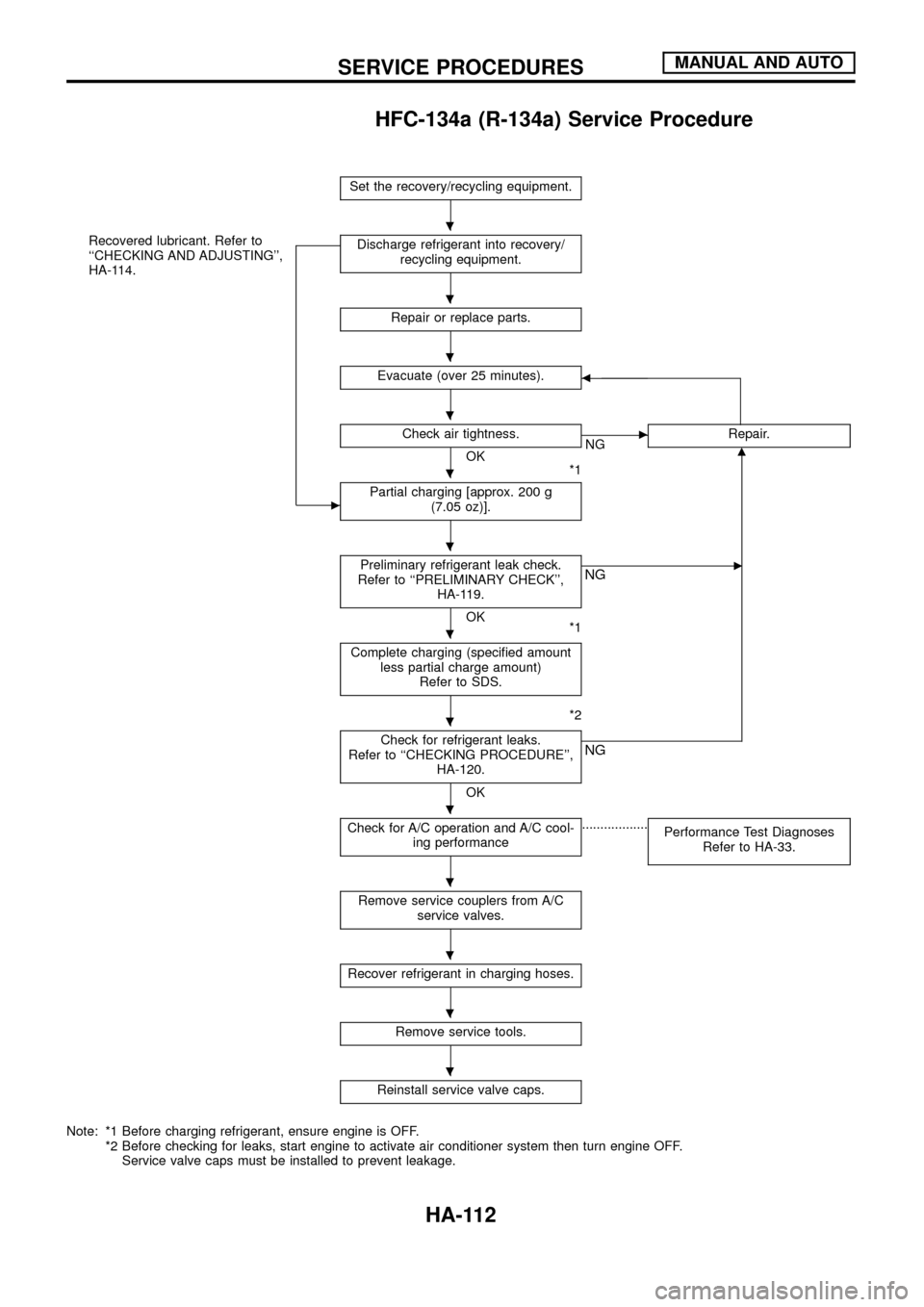
Set the recovery/recycling equipment.
Recovered lubricant. Refer to
``CHECKING AND ADJUSTING'',
HA-114.
c
Discharge refrigerant into recovery/
recycling equipment.
Repair or replace parts.
Evacuate (over 25 minutes).b
Check air tightness.
OK
*1
cNGRepair.m
Partial charging [approx. 200 g
(7.05 oz)].
Preliminary refrigerant leak check.
Refer to ``PRELIMINARY CHECK'',
HA-119.
OK
*1
cNG
Complete charging (speci®ed amount
less partial charge amount)
Refer to SDS.
*2
Check for refrigerant leaks.
Refer to ``CHECKING PROCEDURE'',
HA-120.
OK
NG
Check for A/C operation and A/C cool-
ing performance..................
Performance Test Diagnoses
Refer to HA-33.
Remove service couplers from A/C
service valves.
Recover refrigerant in charging hoses.
Remove service tools.
Reinstall service valve caps.
Note: *1 Before charging refrigerant, ensure engine is OFF.
*2 Before checking for leaks, start engine to activate air conditioner system then turn engine OFF.
Service valve caps must be installed to prevent leakage.
.
.
.
.
.
.
.
.
.
.
.
.
.
SERVICE PROCEDURESMANUAL AND AUTO
HA-112
Page 115 of 128
SETTING OF SERVICE TOOLS AND EQUIPMENT
DISCHARGING REFRIGERANT
WARNING:
Avoid breathing A/C refrigerant and lubricant vapor or mist. Exposure may irritate eyes, nose and
throat. Remove HFC-134a (R-134a) from A/C system using certi®ed service equipment meeting require-
ments of HFC-134a (R-134a) recycling equipment or HFC-134a (R-134a) recovery equipment. If acci-
dental system discharge occurs, ventilate work area before resuming service. Additional health and
safety information may be obtained from refrigerant and lubricant manufacturers.
EVACUATING SYSTEM AND CHARGING REFRIGERANT
SHA539DC
SHA540DC
SERVICE PROCEDURESMANUAL AND AUTO
HFC-134a (R-134a) Service Procedure (Cont'd)
HA-113
Page 117 of 128
jA
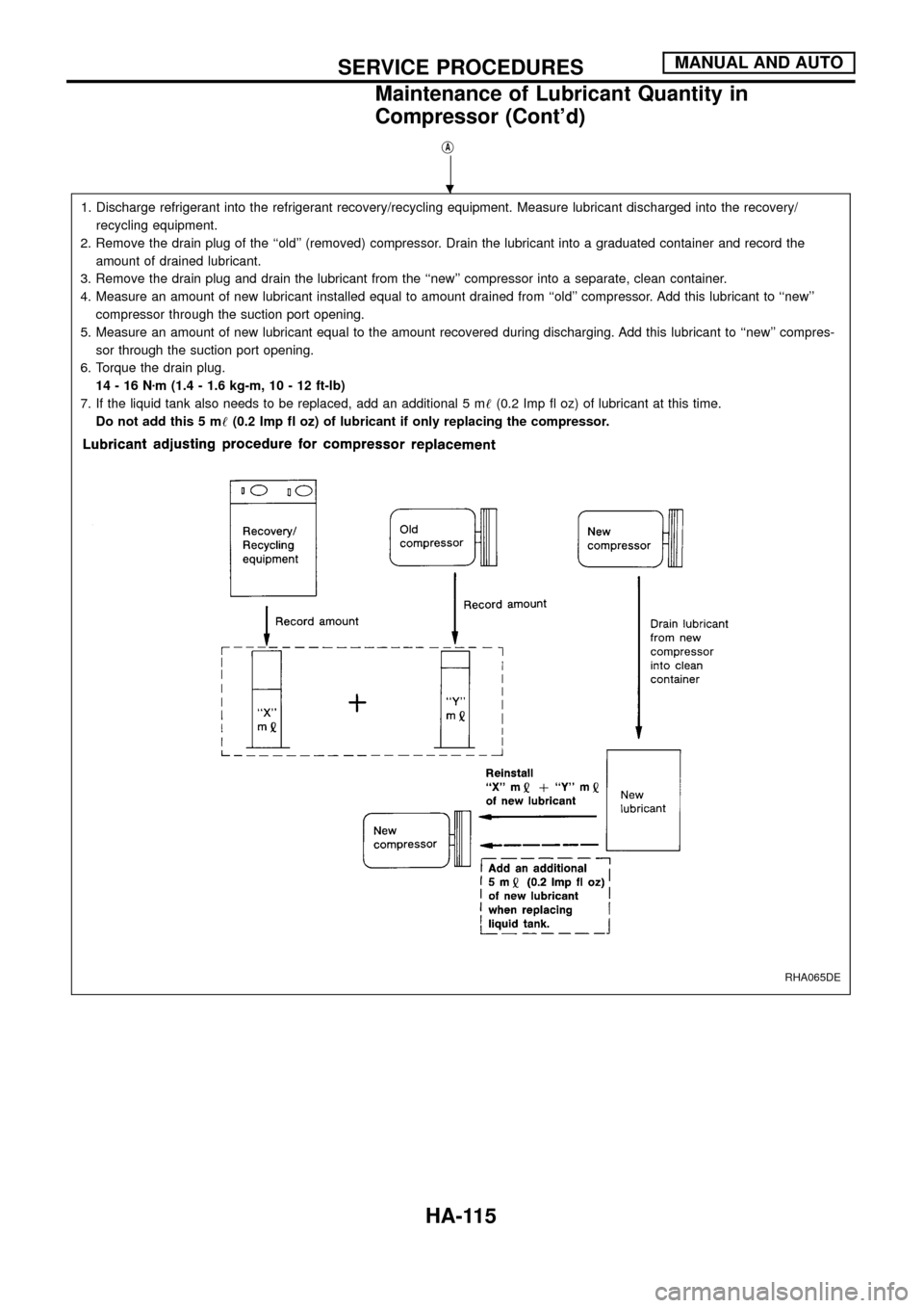
1. Discharge refrigerant into the refrigerant recovery/recycling equipment. Measure lubricant discharged into the recovery/
recycling equipment.
2. Remove the drain plug of the ``old'' (removed) compressor. Drain the lubricant into a graduated container and record the
amount of drained lubricant.
3. Remove the drain plug and drain the lubricant from the ``new'' compressor into a separate, clean container.
4. Measure an amount of new lubricant installed equal to amount drained from ``old'' compressor. Add this lubricant to ``new''
compressor through the suction port opening.
5. Measure an amount of new lubricant equal to the amount recovered during discharging. Add this lubricant to ``new'' compres-
sor through the suction port opening.
6. Torque the drain plug.
14-16Nzm (1.4 - 1.6 kg-m, 10 - 12 ft-lb)
7. If the liquid tank also needs to be replaced, add an additional 5 m!(0.2 Imp ¯ oz) of lubricant at this time.
Do not add this 5 m!(0.2 Imp ¯ oz) of lubricant if only replacing the compressor.
RHA065DE
.
SERVICE PROCEDURESMANUAL AND AUTO
Maintenance of Lubricant Quantity in
Compressor (Cont'd)
HA-115
Page 128 of 128
General Speci®cations
COMPRESSOR
Model ZEXEL make DKS-17CH
Type Swash plate
Displacement cm
3(cu in)/rev. 168 (10.25)
Cylinder bore x stroke mm (in) 37.0 x 25.8 (1.457 x 1.016)
Direction of rotationClockwise
(Viewed from drive end)
Drive belt A Type
LUBRICANT
Model ZEXEL make DKS-17CH
Type KLH00-PAGS0
Capacity m!(lmp ¯ oz)
Total in system 300 (10.6)
Compressor (Service parts)
charging amount300 (10.6)
Inspection and Adjustment
REFRIGERANT
Front A/C
Type HFC-134a (R-134a)
Capacity kg (lb)0.75 - 0.85
(1.65 - 1.87)
ENGINE IDLING SPEED (When A/C is ON.)
+Refer to EC section.
BELT TENSION
+Refer to MA section (``Checking Drive Belts'',
``ENGINE MAINTENANCE'').
COMPRESSOR
Model DKS-17CH
Clutch disc-to-pulley clearance
mm (in)0.3 - 0.6
(0.012 - 0.024)
SERVICE DATA AND SPECIFICATIONS
(SDS)MANUAL AND AUTO
HA-126