Page 65 of 128

Self-diagnosis
INTRODUCTION AND GENERAL DESCRIPTION
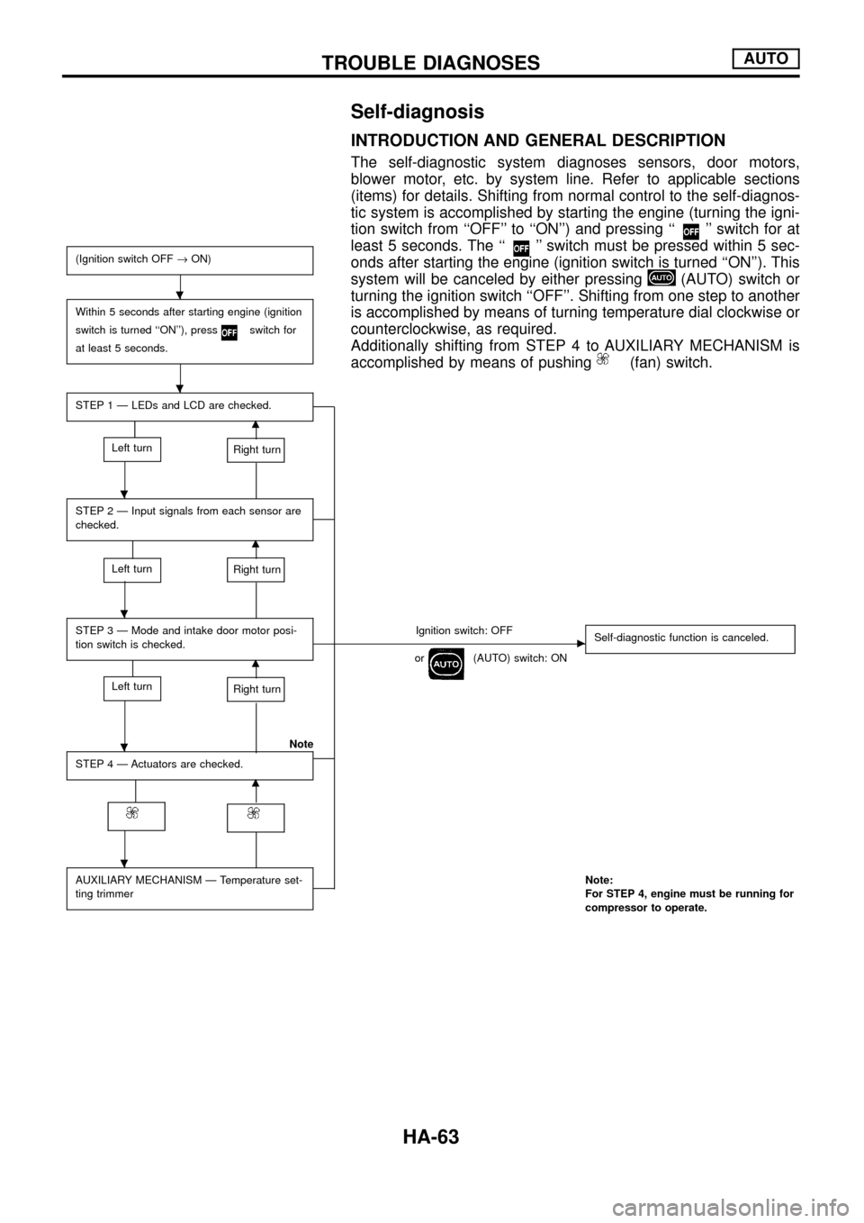
The self-diagnostic system diagnoses sensors, door motors,
blower motor, etc. by system line. Refer to applicable sections
(items) for details. Shifting from normal control to the self-diagnos-
tic system is accomplished by starting the engine (turning the igni-
tion switch from ``OFF'' to ``ON'') and pressing ``
'' switch for at
least 5 seconds. The ``
'' switch must be pressed within 5 sec-
onds after starting the engine (ignition switch is turned ``ON''). This
system will be canceled by either pressing
(AUTO) switch or
turning the ignition switch ``OFF''. Shifting from one step to another
is accomplished by means of turning temperature dial clockwise or
counterclockwise, as required.
Additionally shifting from STEP 4 to AUXILIARY MECHANISM is
accomplished by means of pushing
(fan) switch.
(Ignition switch OFF®ON)
Within 5 seconds after starting engine (ignition
switch is turned ``ON''), press
switch for
at least 5 seconds.
STEP 1 Ð LEDs and LCD are checked.
m
Left turnRight turn
STEP 2 Ð Input signals from each sensor are
checked.
m
Left turnRight turn
STEP 3 Ð Mode and intake door motor posi-
tion switch is checked.Ignition switch: OFFc
or(AUTO) switch: ONSelf-diagnostic function is canceled.m
Left turnRight turn
Note
STEP 4 Ð Actuators are checked.
m
AUXILIARY MECHANISM Ð Temperature set-
ting trimmerNote:
For STEP 4, engine must be running for
compressor to operate.
.
.
.
.
.
.
TROUBLE DIAGNOSESAUTO
HA-63
Page 66 of 128
STEP-BY-STEP PROCEDURE
Turn ignition switch ON.
Set in self-diagnostic mode. Within 5 sec-
onds after starting engine (ignition switch is
turned ``ON''.), press
switch for at
least 5 seconds.
STEP 1 - LEDs AND LCD ARE CHECKED.
Do all LEDs and LCD illuminate?
Ye s
cNo
Malfunctioning
switch, LED or LCD.
Replace A/C auto amp.
Turn temperature dial clockwise.
Advance to self-diagnosis STEP 2?
Ye s
cNo
Malfunctioning temperature
dial.
Replace A/C auto amp.
Turn temperature dial counterclockwise.
Return to self-diagnosis STEP 1?
Ye s
cNo
Malfunctioning temperature
dial.
Replace A/C auto amp.
Turn temperature dial clockwise.
jA
(Go to next page.)
RHA526G
RHA527G
.
.
.
.
.
.
.
.
TROUBLE DIAGNOSESAUTO
Self-diagnosis (Cont'd)
HA-64
Page 70 of 128
AUXILIARY MECHANISM: Temperature setting trimmer
The trimmer compensates for differences in range of 3ÉC between
temperature setting (displayed digitally) and temperature felt by
driver.
Operating procedures for this trimmer are as follows:
+Begin Self-diagnosis STEP 4 mode.
+Press
(fan) switch to set system in auxiliary mode.
+Turn temperature dial clockwise or counterclockwise as
desired. Temperature will change at a rate of 1ÉC each time a
switch is pressed.
When battery cable is disconnected, trimmer operation is can-
celed. Temperature set becomes that of initial condition, i.e.
0ÉC.
RHA581G
TROUBLE DIAGNOSESAUTO
Self-diagnosis (Cont'd)
HA-68
Page 83 of 128

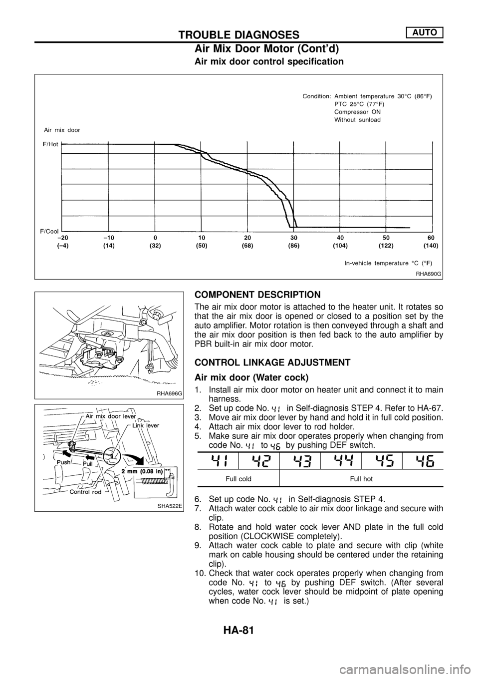
Air mix door control speci®cation
COMPONENT DESCRIPTION
The air mix door motor is attached to the heater unit. It rotates so
that the air mix door is opened or closed to a position set by the
auto ampli®er. Motor rotation is then conveyed through a shaft and
the air mix door position is then fed back to the auto ampli®er by
PBR built-in air mix door motor.
CONTROL LINKAGE ADJUSTMENT
Air mix door (Water cock)
1. Install air mix door motor on heater unit and connect it to main
harness.
2. Set up code No.
in Self-diagnosis STEP 4. Refer to HA-67.
3. Move air mix door lever by hand and hold it in full cold position.
4. Attach air mix door lever to rod holder.
5. Make sure air mix door operates properly when changing from
code No.
toby pushing DEF switch.
Full cold Full hot
6. Set up code No.in Self-diagnosis STEP 4.
7. Attach water cock cable to air mix door linkage and secure with
clip.
8. Rotate and hold water cock lever AND plate in the full cold
position (CLOCKWISE completely).
9. Attach water cock cable to plate and secure with clip (white
mark on cable housing should be centered under the retaining
clip).
10. Check that water cock operates properly when changing from
code No.
toby pushing DEF switch. (After several
cycles, water cock lever should be midpoint of plate opening
when code No.
is set.)
RHA690G
RHA696G
SHA522E
TROUBLE DIAGNOSESAUTO
Air Mix Door Motor (Cont'd)
HA-81